EPIC®200 SERIES TWO-MAN HOLE DIGGER
FORM GOM07042001EU, VERSION 1.0
English-EN 6
1. Use extreme caution handling gasoline. Always use UN marked,
European ADR regulation approved container for storage and
transportation of fuel. Shut engine off and allow to cool before fueling.
Never remove fuel tank filler cap or fill fuel tank while engine is running.
Never operate engine without fuel tank filler cap. Select bare ground for
fueling and move at least 3.05 M (10 feet) from fueling spot before
starting engine.
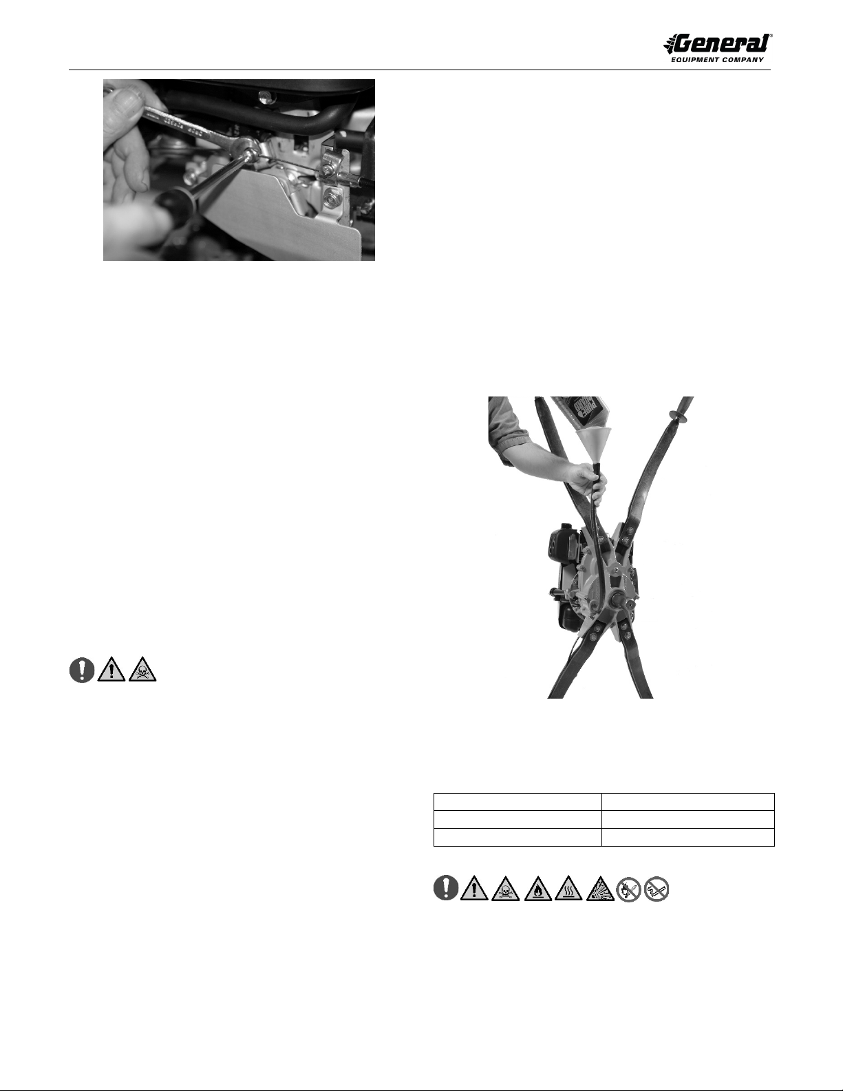
2. Carefully clean filler cap and surrounding area to prevent dirt/debris
falling into fuel tank.
3. Fill fuel tank with fresh, clean, unleaded automotive gasoline. Leaded
“regular” grade gasoline is acceptable substitute. DO NOT USE
GASOLINE CONTAINING METHANOL (WOOD ALCOLHOL). Gasoline
containing maximum 10 percent ethanol/grain alcohol (sometimes
referred to as Gasohol) may be used but requires special care when
storing engine for extended periods.
NOTE: DO NOT use gasoline left over from previous season for easier engine
start-up and prevent poor engine performance.
4. DO NOT completely fill tank. Fill tank to within 6.4 mm (1/4 inch) to 13
mm (1/2 inch) of tank top to allow for fuel expansion. Replace filler cap.
Wipe any fuel spillage and oil if leak is detected from engine and Hole
Digger BEFORE operating engine. DO NOT operate engine until oil leak
is fixed and fuel is wiped away. Properly dispose of any fuel or oil wiped
from machine/rags per international and local regulations. DO NOT allow
fuel or oil to get on clothing. Change clothes immediately if this happens.
7 APPLICATION THEORY & TECHNIQUES
The Hole Digger operates on principle of accessory augers attached to the
transmission drive shaft to rotate and dig holes in a variety of soil types. The
combination of auger diameter, blade, screw bit, soil type and down pressure
supplied by operators will affect the hole digging rate.
Hole digging process is directly controlled by:
1. Soil type.
2. Auger boring head design and diameter selected.
3. When required, sufficient application and/or reduction of machine weight
and/or down force provided by operators to assist auger soil penetration.
4. No two soil types are exactly alike, no two holes can be dug by exact
same method, overall operator feed rates vary. The hole digging process,
along with operator experience, skill and common sense, suggests hole
digging is a matter of trial and error and directly determines overall
success of the job application.
HOLE DIGGING TECHNIQUES
1. Normal Hole Digger operation runs engine at full, governed speed
allowing centrifugal clutch to become firmly engaged. Technique
transmits more usable power to auger, increasing productivity and
reducing component wear. For any soil condition, allow auger to dig at
rate most comfortable to operators, but not cause centrifugal clutch to
overload and slip.
NOTE: Hole Digger is equipped with a centrifugal clutch assembly within the
transmission. The clutch assembly is designed to ALWAYS slip (NOT
DISENGAGE) when overloaded or if auger contacts buried obstruction. When
slipping, clutch still transmits a specific amount of torque to auger. Response
time for clutch to react to overload condition is directly proportional to rotational
speed. With higher rotational speeds (RPM) of clutch at time of overload, it
takes more time for clutch to react and actually slip.
2. In general, pressing down on operator handles is not required to initiate
and/or sustain the digging process. In most moderate density soils, auger
dig rates will not cause centrifugal clutch to overload and slip. In most
soft, low density soils (sandy, etc.), it may be necessary to hold up on
operator handles to reduce auger dig rate due to tendency of any auger
design to cause centrifugal clutch to overload and slip. In most hard, high
density soils (hard clay, etc.), it may be necessary to press down on
operator handles to establish and maintain acceptable dig rates.
3. Some soil conditions may require more power to dig than machine is
capable of delivering for a given auger diameter. To minimize problem,
apply suitable down force by operators and use augers with new screw
bits and blades. DO NOT use more than two operators to apply down
force.
4. When digging in areas filled with known, buried obstructions such as tree
roots, rocks and other debris, operate Hole Digger at less than full (an
intermediate) speed for more rapid release of centrifugal clutch when
obstruction is encountered. This is an industry wide operating procedure.
5. When digging in areas filled with small tree roots, small rocks or other
buried obstructions, allow auger blade to "chip away" at obstruction until
auger can pass by (by working object loose) or go through it (as in
penetrating tree roots). Technique usually involves holding up on
operator handles using minimal auger feed rate. Many times size and
nature of buried object will prevent auger from passing by or going
through it. Instead, remove buried object with shovel or other suitable tool
and proceed to dig to desired depth using Hole Digger.
6. Some job applications may encounter buried obstructions too massive in
size or soil classifications too compacted for Hole Digger use. Another
type equipment of proper size may be required.
7. In most soil conditions, the auger will retract with less effort if allowed to
rotate at slow speed. This procedure, however, will leave more loose soil
at bottom of hole. To minimize amount of loose soil remaining at bottom
of hole, stop rotation before retracting auger.
8. When restarting a Hole Digger with auger in a partially or completely dug
hole extra caution is required. The throttle control can be advanced
beyond idle speed before operators can exercise proper control of Hole
Digger. The accepted procedure (when not using non-flighted auger
extension) is to first remove unit from hole and restart engine per
STARTING ENGINE WITH AUGER ATTACHED in OPERATING
INSTRUCTIONS section of this manual. Return unit to hole with engine
at idle speed and complete hole to desired depth.
9. DO NOT dig an initial “pilot” hole with a smaller auger then use larger
diameter auger to “ream” hole to desired size. This method will prevent
auger screw bit of larger auger from providing sufficient directional
stability during “reaming” process.
10. DO NOT use shovel and/or foreign object to remove loose soil from
around hole area while operating Hole Digger. This can result in shovel
and/or foreign object to become entrapped by rotating auger.
11. Grass and other overgrowth conditions will hamper digging capability of
any auger by becoming "clogged" around auger teeth and screw bit.
Removal of such obstructions from hole location BEFORE digging will
increase digging efficiency and overall productivity.
8 OPERATING INSTRUCTIONS
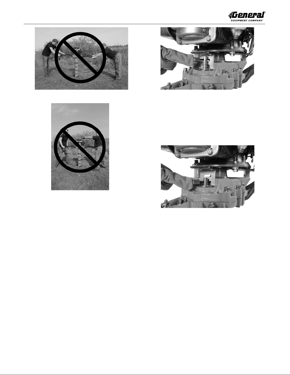
INSTALLING AUGER
1. DO NOT connect auger to Hole Digger while engine is running. Refer to
STOPPING HOLE DIGGER in OPERATING INSTRUCTIONS section of
this manual. To install auger, place Hole Digger with spark plug facing up
to minimize potential oil and/or gasoline entering combustion chamber
and creating a hydraulic lock up.
2. Connect auger to Hole Digger with correct factory supplied auger pin. DO
NOT use any other connecting device, including cap screws, bolts, pins,
etc., that can damage Hole Digger driveshaft and/or auger hub.
STARTING ENGINE WITH AUGER ATTACHED
DO NOT attempt to dig with Hole Digger until Crew Chief and Crew Member
have acknowledged to each other they are ready and are in full control of
machine/accessories. Crew Chief operates engine throttle control with right
hand and is responsible for verbal commands. Crew member operates choke
control and starts engine.