Festo DMES User manual
Other Festo Industrial Equipment manuals
Festo
Festo MS6-SV-C-MK User manual
Festo
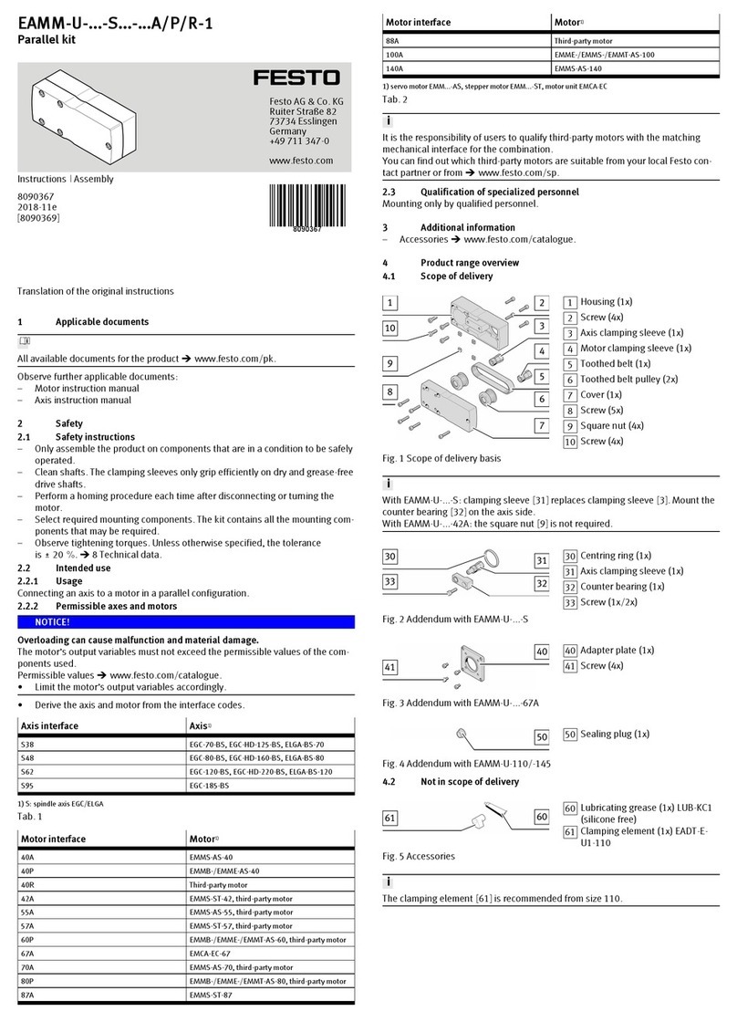
Festo EAMM-U-50-S38-40A Assembly instructions
Festo
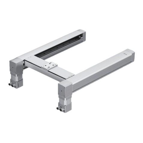
Festo EXCM-30 -PF Series User manual
Festo
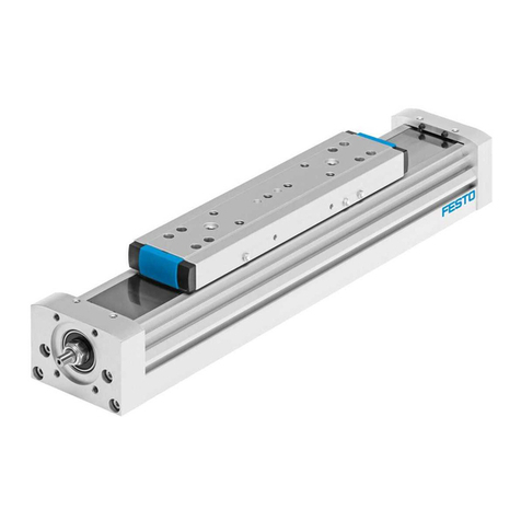
Festo ELGA-BS-KF-70 Setup guide

Festo
Festo Belt Drives 2 Instructions for use
Festo
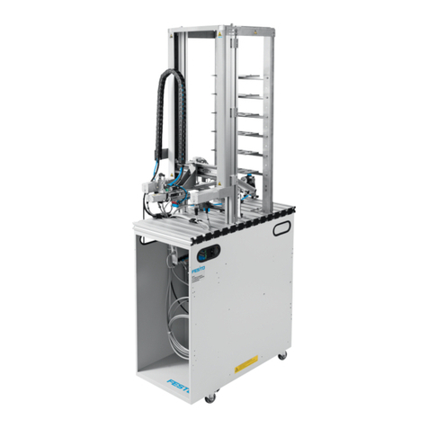
Festo MPS 8049013 Service manual
Festo
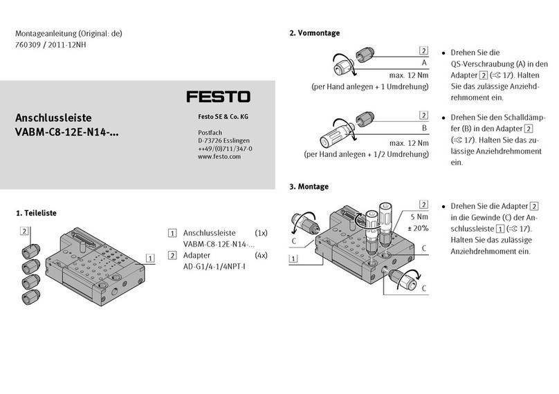
Festo VABM-C8-12E-N14 Series User manual
Festo
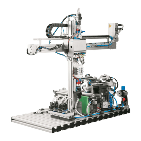
Festo MPS 8046521 User manual
Festo
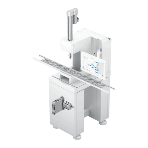
Festo YJKP User manual
Festo
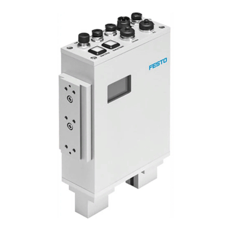
Festo Checkbox Compact CHB-C Series User manual
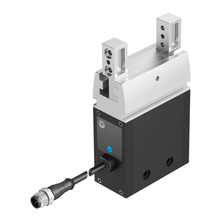
Festo
Festo EHPS User manual

Festo
Festo ELGT-BS User manual
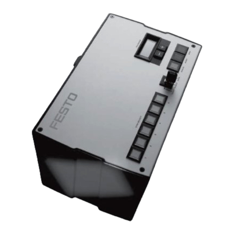
Festo
Festo Checkbox Series User manual
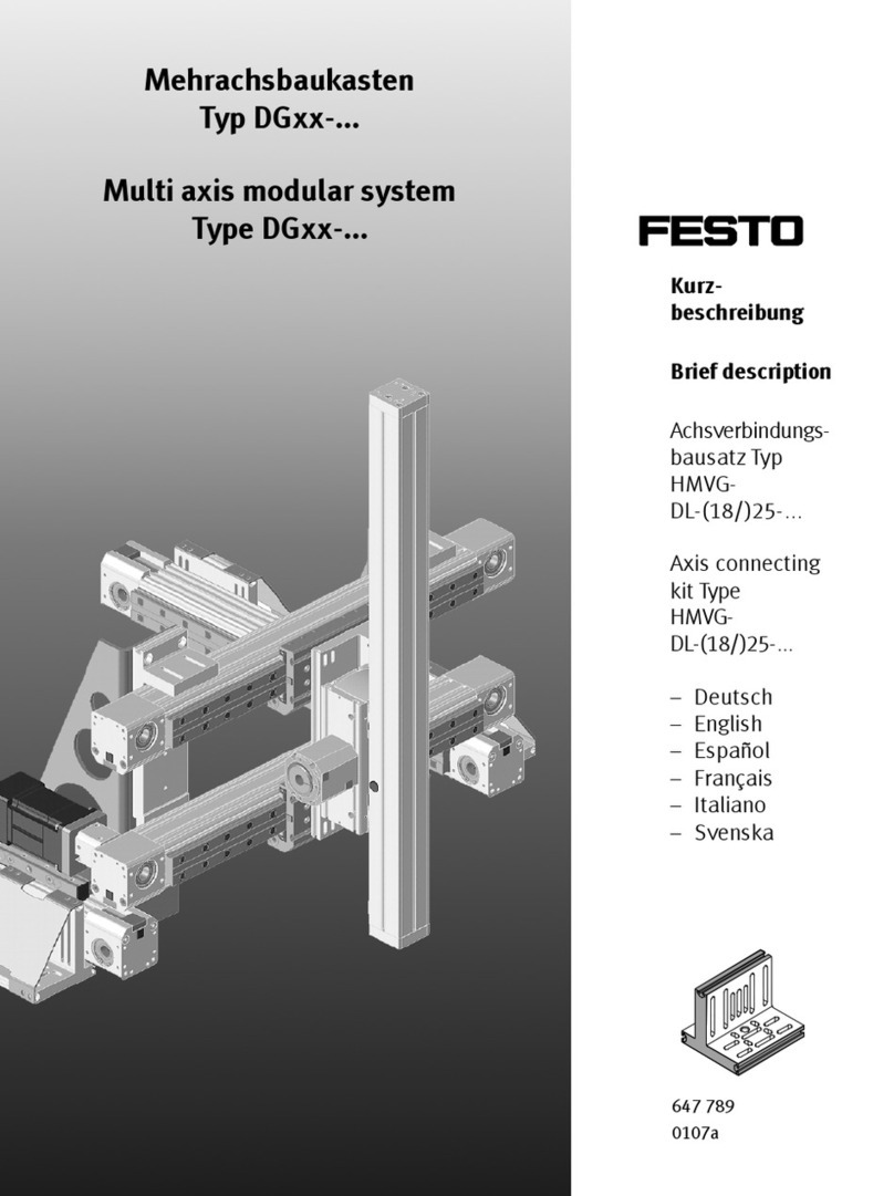
Festo
Festo DG Series Parts list manual
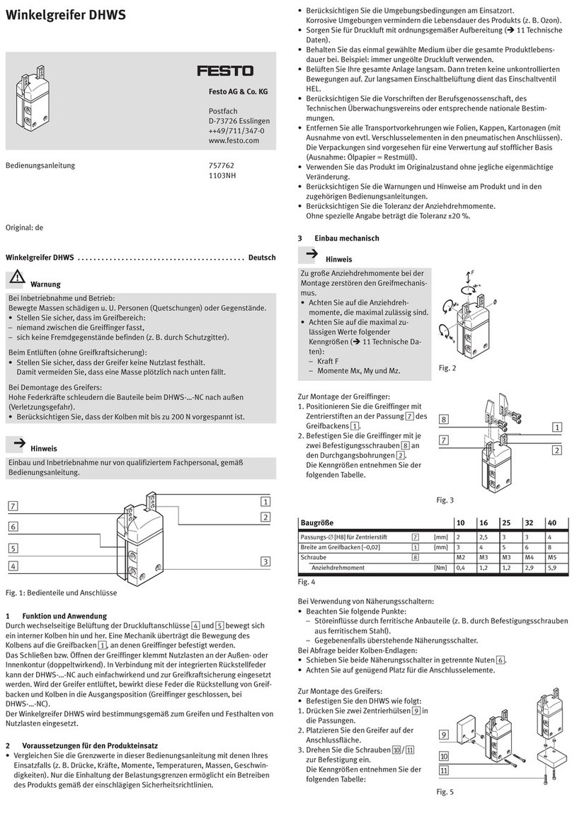
Festo
Festo DHWS User manual

Festo
Festo DHTG-***-P4 User manual
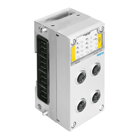
Festo
Festo CPX-F8DE-P User manual

Festo
Festo 586849 User manual
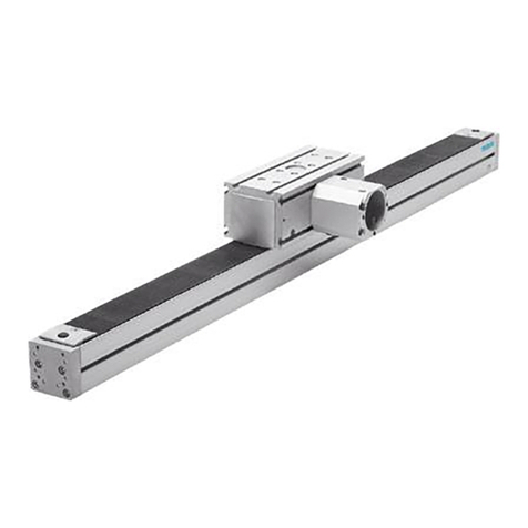
Festo
Festo DGEA Series User manual
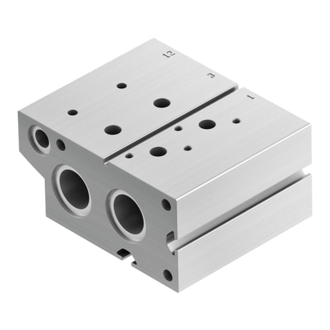
Festo
Festo VABM-B10 EEE Series User manual
