Valmet Flowrox FXM Series Manual

© Valmet, 4FXM70EN - 8/2022
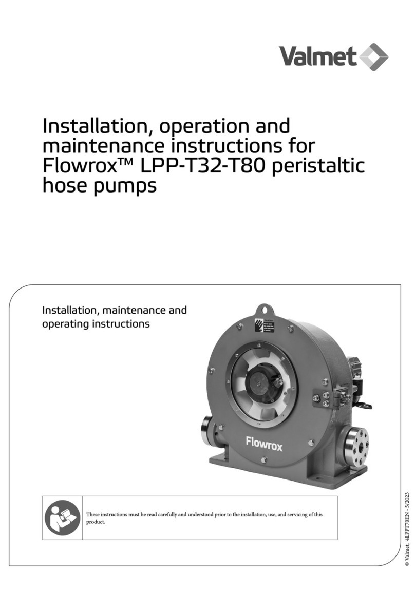
Installation, operation and
maintenance instructions for
Flowrox™ FXM peristaltic metering
tube pumps
These instructions must be read carefully and understood prior to the installation, use, and servicing of this
product.
Installation, maintenance and
operating instructions

4FXM70EN - 8/20222
DISCLAIMER
ALL INTELLECTUAL PROPERTY RIGHTS TO THIS MANUAL “MANUAL” BELONG TO VALMET CORPORATION
“VALMET” WHICH REMAINS THE SOLE OWNER OF THESE RIGHTS. OWNERSHIP OF THESE RIGHTS ARE
NOT TRANSFERRED FROM VALMET TO ANYONE IN CONNECTION WITH THIS MANUAL. THIS MANUAL
IS INTENDED TO BE USED ONLY BY VALMET CUSTOMER AND EXCLUSIVELY FOR THE PURPOSES OF THE
AGREEMENT UNDER WHICH THIS MANUAL IS DELIVERED TO VALMET CUSTOMER. WITHOUT THE PRIOR
WRITTEN EXPLICIT CONSENT FROM VALMET, NO PART OF THIS MANUAL SHALL BE USED, REPRODUCED,
COPIED, TRANSLATED,CONVERTED, ADAPTED, STORED IN A RETRIEVAL SYSTEM , COMMUNICATED OR
TRANSMITTED BY ANY MEANS, OR FOR ANY COMMERCIAL OR OTHER PURPOSES, INCLUDING , BUT NOT
LIMITED TO, SALE, RESALE, LICENS, RENT OR LEASE.
THIS MANUAL PROVIDES INSTRUCTIONS TO CARRY OUT CERTAIN ACTIVITIES AND IS DESIGNED AND
MEANT TO GUIDE AND ASSIST PROFESSIONAL AND PROPERLY TRAINED EXPERTS IN PERFORMING
THEIR FUNCTIONS. EVERYONE MUST BECOME FAMILIAR WITH ALL INSTRTUCTIONS IN THIS MANUAL
BEFORE ANY INSTALLATION, USE, MAINTENANCE, REPAIR OR ANY OTHER ACTIONS OF THE RESPECTIVE
GOODS AND/OR SERVICES WHICH THIS MANUAL APPLIES TO. ALL INSTRUCTIONS MUST BE FOLLOWED
CAREFULLY. HOWEVER, OBSERVANCE OF ANY PART OF THE INSTRUCTIONS PRESENTED IN THIS MANUAL
MAY BE OMITTED IN EVENT WHEN IT IS REQUIRED OR ALLOWED BY LAW
VALMET HAS TAKEN EVERY CARE IN THE PREPARATION OF THE CONTENT OF THIS MANUAL, BUT DOES
NOT MAKE ANY REPRESENTATIONS, WARRANTIES OR GUARANTEES OR, EXPRESS OR IMPLIED, AS TO THE
ACCURACY OR COMPLETENESS OF THIS MANUAL. ALL USERS MUST UNDERSTAND AND BE AWARE THAT
UPDATES AND AMENDMENTS WILL BE MADE FROM TIME TO TIME TO THIS MANUAL. ALL USERS ARE
OBLIGATED TO FIND OUT AND DETERMINE WHETHER THERE HAVE BEEN ANY APPLICABLE UPDATES OR
AMENDMENTS TO THIS MANUAL. NEITHER VALMET NOR ANY OF ITS DIRECTORS, OFFICERS, EMPLOYEES,
SUBCONTRACTORS, SUBSUPPLIERS, REPRESENTATIVES OR AGENTS SHALL BE LIABLE IN CONTRACT,
TORT OR IN ANY OTHER MANNER WHATSOEVER TO ANY PERSON FOR ANY LOSS, DAMAGE, INJURY,
DEATH, LIABILITY, COST OR EXPENSE OF ANY NATURE, INCLUDING WITHOUT LIMITATION INDIRECT,
INCIDENTAL, SPECIAL, CONSEQUENTIAL, PUNITIVE OR DIRECT DAMAGES AND/OR LOSSES ARISING OUT
OF OR IN CONNECTION WITH THE CREATION, DELIVERY, POSSESSION AND/OR USE OF THIS MANUAL.
HOWEVER, NOTHING IN THIS PARAGRAPH IS DEEMED TO EXCLUDE OR RESTRICT ANY LIABILITY WHICH
CANNOT BY MANDATORY LAW BE EXCLUDED.
FLOWROX IS EITHER REGISTERED TRADEMARK OR TRADEMARK OF VALMET CORPORATION OR ITS
SUBSIDIARIES OR AFFILITIATES IN THE UNITED STATES AND/OR IN OTHER COUNTRIES. ALL OTHER
TRADEMARKS, LOGOS, BRANDS AND MARKS DISPLAYED IN THIS MANUAL ARE PROPERTY OF THE
RESPECTIVE OWNERS UNLESS STATED OTHERWISE.
Copyright © 2014-2022 Valmet Corporation. All rights reserved.

34FXM70EN - 8/2022
READ THESE INSTRUCTIONS FIRST!
ese instructions provide information about safe handling and
operation of the product.
If you require additional assistance, please contact the
manufacturer or manufacturer’s representative.
SAVE THESE INSTRUCTIONS!
Addresses and phone numbers are printed on the back cover.
Table of Contents
1 EU DECLARATION OF
CONFORMITY 4
1.1 Introduction 5
1.2 Available Models 5
1.3 Specifications 7
1.4 Materials of construction 8
1.5 Features 8
1.6 Agency Listings 9
2 Installation 10
2.1 Mounting Location 10
2.2 Dimensions 11
2.3 Installing Suction Strainer 12
2.4 Input Power Connections 12
2.5 WIRING TERMINALS AND I/O SCHEMATICS 14
3 How To Operate FXM 16
3.1 Menu Navigation 17
3.2 Configuration Menu 18
4 Input Setup 23
4.1 MAX Flowrate (output calibration) 25
4.2 Contact Input 32
4.3 Remote/Local Control 32
4.4 Conditional Contact Input Naming 33
4.5 Conditional Logic Control 33
5 Output setup ( alarm relays )
34
5.1 Signal Output 35
6 Pump Maintenance 36
6.1 Routine Inspection and Maintenance 36
6.2 How to Clean and Lubricate the Pump 36
6.3 Reverse Rotor Rotation 36
6.4 Tube Replacement 37
6.5 FLOWROX Model FXM2 replacement parts list 40
6.6 FLOWROX Model FXM3 replacement parts list 42
APPENDICES 44
Warranty 44

4FXM70EN - 8/2022
4
1 EU DECLARATION OF CONFORMITY
is declaration is issued under the sole responsibility of the manufacturer:
Valmet Flow Control Oy
Marssitie 1
53600 Lappeenranta
Finland
Tel. +358 (0)10 417 5000
Product model/type: FXM Peristaltic Metering Tube Pump
e object of the declaration described above is in conformity with the relevant Union harmonisation legislation:
Machinery Directive 2006/42/EC: Annex II A
Electro-Magnetic Compatibility Directive 2014/30/EU
Low Voltage Directive 2014/35/EU
Follow the pump installation, operating and maintenance instructions in this manual.
Person authorised to compile the technical le is Technology Manager Jarmo Partanen.
On behalf of Valmet Flow Control Oy
In Lappeenranta, 13th May 2022
Riku Salojärvi
Head of Operations

54FXM70EN - 8/2022
1.1 Introduction
Congratulations on purchasing the Flowrox variable speed Peristaltic Metering Pump.
Your Flowrox pump is pre-congured for the tubing that shipped with your metering pump.
Your new pump has been pressure tested at the factory with clean water before shipping. You may notice trace amounts of clean water in the
pre-installed tube assembly. This is part of our stringent quality assurance program.
Flowrox FXM pumps are for industrial and laboratory applications. Only qualified personnel is allowed to install and operate the pump.
1.2 Available Models
Feed rate Max Max FXM2 Model Numbers
Speed Pressure
FXM2 Tube Pumps Norprene®
Meets FDA criteria for food | Excellent chemical resistance | CIP | SIP
liter/h
(gal/h)
ml/min
(oz/min) RPM bar
(psi) 115V AC (US) 230V AC (US) 230V AC (EU) 230V AC (UK) 230V AC (AUS)
.002 - 11
(0.0005 - 2.9)
.04 - 183
(0.0014 - 6.2) 175 8.6
(125) FXM2-S-34-N011 FXM2-S-35-N011 FXM2-S-36-N011 FXM2-S-37-N011 FXM2-S-38-N011
.018 - 92
(0.0048 - 24.3)
.3 - 1533
(0.010 - 52.5) 175 8.6
(125) FXM2-S-34-N092 FXM2-S-35-N092 FXM2-S-36-N092 FXM2-S-37-N092 FXM2-S-38-N092
.035 - 176
(0.009 - 46.5)
.6 - 2933
(0.020 - 99.2) 175 2.1
(30) FXM2-S-34-N176 FXM2-S-35-N176 FXM2-S-36-N176 FXM2-S-37-N176 FXM2-S-38-N176
FXM2 Tube Pumps Tygon lined Norprene®
Meets FDA criteria for food | Superior chemical resistance
liter/h
(gal/h)
ml/min
(oz/min) RPM bar
(psi) 115V AC (US) 230V AC (US) 230V AC (EU) 230V AC (UK) 230V AC (AUS)
.030 - 165
(0.008 - 43.6)
.5 - 2750
(0.017 - 93.0) 175 3.5
(50) FXM2-S-34*-T165 FXM2-S-35*-T165 FXM2-S-36*-T165 FXM2-S-37*-T165 FXM2-S-38*-T165
FXM2 Tube Pumps Tygothane®
Meets FDA criteria for food | Resistant to oils, greases and fuels
liter/h
(gal/h)
ml/min
(oz/min) RPM bar
(psi) 115V AC (US) 230V AC (US) 230V AC (EU) 230V AC (UK) 230V AC (AUS)
.030 - 162
(0.008 - 42.8)
.5 - 2700
(0.017 - 91.3) 175 4.5
(65) FXM2-S-34*-G162 FXM2-S-35*-G162 FXM2-S-36*-G162 FXM2-S-37*-G162 FXM2-S-38*-G162

4FXM70EN - 8/2022
6
Feed rate Max Max FXM2 Model Numbers
Speed Pressure
FXM3 Tube Pumps Norprene®
Meets FDA criteria for food | Excellent chemical resistance | CIP | SIP
liter/h
(gal/h)
ml/min
(oz/min) RPM bar
(psi) 115V AC (US) 230V AC (US) 230V AC (EU) 230V AC (UK) 230V AC (AUS)
.05- 268
(0.013 - 70)
0.9 - 5617
(0.030 - 189.9) 175 2.1
(30)
FXM3-S-
34*-N269
FXM3-S-
35*-N269
FXM3-S-
36*-N269
FXM3-S-
37*-N269
FXM3-S-
38*-N269
.11 - 529
(0.029 - 139.7)
1.8 - 8550
(0.061 - 289.1) 175 3.4
(50)
FXM3-S-
34*-N529
FXM3-S-
35*-N529
FXM3-S-
36*-N529
FXM3-S-
37*-N529
FXM3-S-
38*-N529
.17 - 840
(0.045 - 221.9)
2.8 - 14000
(0.095 - 473.4) 175 2.1
(30)
FXM3-S-
34*-N840
FXM3-S-
35*-N840
FXM3-S-
36*-N840
FXM3-S-
37*-N840
FXM3-S-
38*-N840
FXM3 Tube Pumps Tygon lined Norprene®
Meets FDA criteria for food | Superior chemical resistance
liter/h
(gal/h)
ml/min
(oz/min) RPM bar
(psi) 115V AC (US) 230V AC (US) 230V AC (EU) 230V AC (UK) 230V AC (AUS)
.06 - 307
(0.016 - 81.2)
1.0 - 6167
(0.034 - 208.5) 175 2.1
(30)
FXM3-S-
34*-T300
FXM3-S-35*-
T300
FXM3-S-36*-
T300
FXM3-S-37*-
T300
FXM3-S-38*-
T300
FXM3 Tube Pumps Tygothane®
Meets FDA criteria for food | Resistant to oils, greases and fuels
liter/h
(gal/h)
ml/min
(oz/min) RPM bar
(psi) 115V AC (US) 230V AC (US) 230V AC (EU) 230V AC (UK) 230V AC (AUS)
.06 - 350
(0.016 - 94.2)
1.0 - 5833
(0.034 - 197.2) 175 4.5
(65)
FXM3-S-
24*-G350
FXM3-S-35*-
G350
FXM3-S-36*-
G350
FXM3-S-37*-
G350
FXM3-S-38*-
G350
• The Flowrox Peristaltic Pump’s motor speed is linear over
the entire 0.02% to 100% adjustment range.
• Output versus pressure is nearly linear in all models.
Larger tubes exhibit greater losses.
• The pressure, temperature, operational speed, application
media and viscosity will affect hose lifetime.
• For optimum tube life, specify the pump so that it operates
at the lowest possible RPM and pressure.
* Inlet/outlet connection type:
blank = 3/8” OD x 1/4” ID tubing compressions type
connections (available on FXM2 only)
P = 1/2” MPT
B = 1/2” ID hose barb type connections (available on FXM3
models only)

74FXM70EN - 8/2022
1.3 Specifications
Maximum working pressure (excluding pump tubes):
FXM2: 8.6 bar / 125 psi
FMX3: 4.5 bar / 65 psi
Note: see individual pump tube assembly maximum pressure
ratings in Section 1.2 (Available Models)
Maximum Fluid temperature:
54°C / 129°F
Minimum and maximum ambient operating or storage
temperature:
0°C to 46°C / 32° to 115°F
Operating Voltage:
FXM-M2 MODELS: 96 to 264VAC-50/60Hz, 190W
FXM-M3 MODELS: 96 to 264VAC-50/60Hz, 190W
Power Cord Options:
115V60Hz = NEMA 5/15 (USA)
230V60Hz = NEMA 6/15 (USA)
230V50Hz = CEE 7/VII (EU)
230V50Hz = BS 1363 (UK)
230V50Hz = AS 3112 (Australia/New Zealand)
Enclosure:
NEMA 4X (IP66), Polyester powder coated aluminum.
Maximum Overall Dimensions:
FXM-M2 models (WxHxD): 236 mm x 307 mm x 329 mm
FXM-M3 models (WxHxD): 320 mm x 383 mm x 387 mm
Approximate shipping wt:
FXM-M2 models: 14.0 kg / 31 lbs.
FXM-M3 models: 22.0 kg /48.5 lbs.
Motor speed adjustment range 5.000:1:
0.02% - 100% motor speed
Motor speed adjustment resolution:
0.1% increments > 1% motor speed
0.01% increments > 0.2% - 1% motor speed
Maximum viscosity:
5,000 centipoise
Maximum suction li:
9 m, 0.9 bar / 29.5 , 13 psi
Display
3.5” Backlit high resolution
Display Languages
English, Spanish, French, German, Russian or Finnish
selectable.
Keypad
Eleven button positive action tactile switch keypad.
Security
Programmable 4-digit password.
Other:
Indoor use only
Altitude: up to 2000 m / 6561.7
Humidity: 0-95% RH
Mains uctuations: +/- 10%
Overvoltage category: II
Wet location: no
Pollution degree: 2

4FXM70EN - 8/2022
8
1.4 Materials of construction
Wetted components:
Pump Tube Assembly (Model Specic - 2 provided):
Tubing: . . . . . . . . . . . . Norpreneor Tygon lined Norprene
or Tygothane
Adapter ttings: . . . . . . PVDF
Connections tubings:
Suction Tubing: . . . . . . . . 3/8” OD x 1/4” ID x 10’ Clear PVC
(FXM2)
Discharge Tubing: . . . . . . . 3/8” OD x 1/4” ID x 10’
Polyethylene (FXM2)
Suction Strainer: . . . . . . . . Polypropylene
Non-Wetted components:
Enclosure:
A356 (AlSi7Mg) Aluminum (Polyester powder coated)
Pump Head:
PBT GF30
Pump Head Cover:
Clear Acrylic
Permanently lubricated sealed motor sha support ball
bearing.
Cover Screws:
Stainless Steel umb Screws
Roller Assembly:
Rotor:..................................PBT GF30
Rollers: ..................... ..........POM
Roller Bearings:......................Ball Bearings
Motor Sha:
Chrome plated steel
Tube Leak Detection (TLD) System Sensor pins,
non-contact:
Brass
Power Cord and Connector:
Power cord with plug (see page 7, 14) and Amphenol female
pin connector type DC-03BFFB
Connector in pump PWF-03-PMMS SC7001, male pins
copper alloy
Mounting plate:
Stainless steel AISI 316
1.5 Features
• Peristaltic pump design does not have valves that can
clog requiring maintenance.
• Self priming even against maximum line pressure.
By-pass valves are not required. Cannot vapor lock or
lose prime. Siphoning cannot occur.
• Output rates to: 840 liter/h and pressures up to 8.6 bars.
• No maintenance brushless variable speed motor.
• Specially engineered tubing for long life at high
pressures.
• Non-contact capacitive Tube Leak Detection (TLD)
system. Senses tube failure by detecting chemical in the
pump head. No false triggering.
• 5000:1 turndown ratio.
• SCADA Inputs include: 4-20mA, 0-10VDC, and Pulse
inputs for remote external speed control and 0-30 VDC /
contact closure remote start/stop.
• Operator friendly digital touch pad with menu driven
software.
• Multi-color backlit LCD displays remote/local control
status, motor speed, output rate, input signal values,
service and alarm status.
• Outputs include: Scalable 4-20mA or pulse, one
250V/6A relay and four 125VAC 0.5Amp / 30VDC
2Amp contact closures assignable to monitor up to 17
different pump functions including TLD, FVS, remote/
local control setting, motor on, fault, current operating
mode, and others.
• Two CNC precision machined squeeze rollers and two
alignment rollers for optimum squeeze, unparalleled
accuracy, and tube life.
• Heavy duty rotor - plastic rotor means no flexing and
increased accuracy (no metal springs or hinges to
corrode).
• Inject at maximum pressure in either direction
(clockwise and counter clockwise).
• Compatible with output Flow Verification Sensor (FVS)
system.
• Auto-restart feature which will restore pump to operating
state it was in when power was lost.

94FXM70EN - 8/2022
Enclosure Rating:
NEMA 4X: Constructed for either indoor or outdoor use to
provide a degree of protection to personnel against incidental
contact with enclosed equipment; to provide a degree of
protection against falling dirt, rain, sleet, snow, windblown
dust, splashing water, and hose-directed water; and that will
be undamaged by external formation of ice on enclosure.
IP66: No ingress of dust; complete protection against contact.
Water projected in powerful jets against enclosure from any
direction shall have no harmful eects.
1.6 Agency Listings
This pump is MET listed (E115105) to conforms to the
following:
UL Standard 778, 6th edition, Motor-Operated Water
Pumps
Certified to CAN/CSA Standard C22.2 No. 108-14, 5th
edition, Liquid Pumps
EN 61010-1, Safety requirements for electrical
equipment for measurement, control, and laboratory use
- Part 1: General requirements
Low Voltage Directive 2014/35/EU
EMC Directive 2014/30/EU
Machinery Directive 2006/42/EC
In this manual, the following symbols are used to highlight
the parts requiring particular attention:
Hazard severity panels.
DANGER!
DANGER indicates a hazard with a high level of risk
which, if not avoided, will result in death or serious injury.
WARNING!
WARNING indicates a hazard with a medium level of
risk which, if not avoided, could result in death or serious
injury.
CAUTION!
CAUTION indicates a hazard with a low level of risk
which, if not avoided, could result in minor or moderate
injury.
Symbol Explanation
Risk to personal safety:
Neglecting the safety measures can cause serious injury
or death.
Electrocution hazard.
Crushing hazard.
Read the operation and maintenance instructions:
Read and understand the operation and maintenance
instructions before using the product.
Mandatory action symbol:
Obey these instructions to prevent machine malfunctions.
Ground, Protective Conductor Terminal

4FXM70EN - 8/2022
10
2 Installation
Risk of chemical overdose. Make sure pump does not
overdose chemical during backwash and periods of no
flow in circulation system.
Always wear protective clothing, face shield, safety
glasses and gloves when working on or near your
metering pump. Additional precautions should be taken
depending on solution being pumped. Refer to MSDS
precautions from your solution supplier.
All diagrams are strictly for guideline purposes only.
Always consult an expert before installing metering
pump on specialized systems. Metering pump should be
serviced by qualified persons only.
2.1 Mounting Location
Choose an area located near chemical supply tank, chemical
injection point, and electrical supply. Install pump where
it can be easily serviced. Note, Pump is not certied for
classied EX/ATEX areas
• Mount pump to a secure surface using fixing plate.
• Mount pump close to injection point. Keep inlet
(suction) and outlet (discharge) tubing as short as
possible. Longer discharge tubing increases back pressure
at pump head.
• A backflow prevention check valve is recommended at
the discharge of the pump to prevent system fluid from
flowing back through the pump during tube replacement
or if the tube should rupture.
• A pressure relief valve is recommended at the discharge
of the pump to prevent premature wear and damage to
the pump tube in the event the discharge line becomes
blocked.
• The FXM does not require back pressure. Pressure
regulator valves are not required. Keep the discharge
pressure as low as possible to maximize tube life.
• An anti-siphon valve is not required, siphoning cannot
occur.

114FXM70EN - 8/2022
2.2 Dimensions
Dimensions in mm (inches in parenthesis)
FXM2:
FXM3:

4FXM70EN - 8/2022
12
2.3 Installing Suction Strainer
Proper eye and skin protection must be worn when
installing and servicing pump.
This pump has been evaluated for use with water only.
Suction tube strainer, dimensions valid for FXM2 only
2.4 Input Power Connections
WARNING!
Electrocution hazard.
Cord connected models are supplied with a grounding
conductor and grounding-type attachment plug.
To reduce risk of electric shock, be certain that it is
connected only to a properly grounded, grounding-type
receptacle.
Disconnect electricity before removing the termination
box cover.
Electrical connections and grounding (earthing) must
conform to local wiring codes.
• Be certain to connect pump to proper supply voltage.
Using incorrect voltage will damage pump and may
result in injury. Voltage requirement is printed on pump
serial label.
• Input power range is 96VAC to 264VAC 50/60 Hz.
• Voltage Selection is automatically detected and adjusted
by power supply. No mechanical switch necessary.
• Use voltage your power cord is rated for.
• Cord connected models are supplied with a ground wire
conductor and a grounding type attachment plug (power
cord). To reduce risk of electric shock, be certain that
power cord is connected only to a properly grounded,
grounding type receptacle.
• Never strap control (input / output) cables and power
cables together.
• Power Interruption: This pump has an auto-restart
feature which will restore pump to operating state it was
in when power was lost.
When in doubt regarding your electrical installation,
contact a licensed electrician.
Power cord installation to the pump:
• Due to regulations Amphenol power cord connection
to the pump (see page 14) has been secured with Loctite
425 thread locking.
• If you have to open this connection, please use a tool,
required max torque is 0.5Nm (4 in.-lbs).
• When installing the cord insert the Amphenol connector
plug into the Amphenol power connector on pump back
side, notice the pin assignment in the connector, see page
14.
• Rotate the connector nut in the cable to secure
connection tightness, use Loctite 425 locking.

134FXM70EN - 8/2022
TERMINATION BOX COVER POWER CORD OPTIONS
Cable and conduit connectors included
QT Y. DESCRIPTION
3A M20 CABLE GLAND, ACCEPTABLE CABLE DIAMETER FROM 7 TO 13 MM
1B POWER CORD CONNECTOR PWF-03PMMS-SC7001
1C ETHERNET CONNECTOR RJ45
1D PROFIBUS CONNECTOR (IN FUTURE OPTION)

4FXM70EN - 8/2022
14
2.5 WIRING TERMINALS AND I/O
SCHEMATICS
Connector box layout

154FXM70EN - 8/2022
FUNCTION TERMINAL PIN# PIN NAME RATING ELECTRICAL SP.
Input: 4-20 mA J9
34-20mA input (+) positive 120 Ohm impedance,
non-powered loop
2GND (-) negative
Input: Pulse J9
1Pulse (+) positive high: 2 to 30 VDC
low: < 0,7 VDC
Rising edge triggered
2GND (-) negative
Input:
Frequency, AC
sine wave, TTL,
CMOS
J10
2Frequency input (+) positive 0-1000 Hz
high: 2 to 30 VDC
low: < 0,7 VDC
1GND (-) negative
Input:
0-10V DC
J11 10-10V input (+) positive
Max load 50 mA
2+15VDC (+) positive
J9 2GND (-) negative
Input:
FVS System J12
2SIG (+) positive SIG high: 2 to 30 VDC
SIG low: < 0,7 VDC
1 + (+) positive +5V
3 - (-) negative GND
Input:
Remote 1 J13
2RMT (+) positive RMT high: 2 to 30 VDC
RMT low: < 0,7 VDC
1DRY (+) positive 5 VDC / 1kOhm
3COM (-) negative GND
Input:
Remote 2 J14
2RMT2 (+) positive RMT2 high: 2 to 30 VDC
RMT2 low: < 0,7 VDC
1DRY2 (+) positive 5 VDC / 1kOhm
Output:
4-20 mA J7
24-20mA output (+) positive
900 Ohm load max.
1GND (-) negative
Output:
Frequency J8 2Frequency
output (+) positive open collector
0-1000 Hz
50% duty cycle
1GND (-) negative
Output:
Relay, 6 Amp J2
1NO normally open
Form C
6 Amp max at 250 VAC,
2 Amp max at 24 VDC
2COM common
3NC normally
closed
Output:
Contact
Closure 1
J3
1NC normally
closed Form C
0,5 Amp max at 125 VAC,
2 Amp max at 30 VDC
2COM common
3NO normally open
Output:
Contact
Closure 2
J4
1NC normally
closed Form C
0,5 Amp max at 125 VAC,
2 Amp max at 30 VDC
2COM common
3NO normally open
Output:
Contact
Closure 3
J5
1NC normally
closed Form C
0,5 Amp max at 125 VAC,
2 Amp max at 30 VDC
2COM common
3NO normally open
Output:
Contact
Closure 4
J6
1NC normally
closed Form C
0,5 Amp max at 125 VAC,
2 Amp max at 30 VDC
2COM common
3NO normally open
Connector specications

4FXM70EN - 8/2022
16
3 How To Operate FXM
FXM Control Panel – Button Operation
A sample of pump displays showing items on main display.

174FXM70EN - 8/2022
3.1 Menu Navigation
Use MENU button to enter menu for setting up pump.
Use UP or DOWN arrows to navigate through menu.
Active option appears on pump display in inverse text.
Arrow symbol signies top of a menu tree. is means you
can go further within menu.
Within Menu of pump, each screen you enter will have a title
located along top. is will display the menu that is currently
active, or this will be the setting you are conguring.
To back out of menu, select ← Back line located at end of list.
en press ENTER button. is will take you back one level.
When menu list extends above or below height of display,
a scroll bar will appear on le side. Press DOWN arrow to
scroll down to end of list to see a list of all available options.
Scroll bar example:
While making a selection where only one choice is allowed,
you will see a radio button.
Radio button example:
Black tick shows item is selected
Outline with no tick means item is not selected
In a screen where you are making changes, you will see the
mark OK located at bottom of list. You must select OK in
order to leave screen (whether you made a change or not).
Selecting OK will take you back to parent level.
When inputting a numerical value, use UP or DOWN arrow
to scroll through 0 - 9. To move over to next digit use RIGHT
arrow. If you pass your desired digit, you can continuously
press RIGHT arrow until you scroll reach to your desired
digit.
Numeric value example:
Sample screen shots

4FXM70EN - 8/2022
18
3.2 Configuration Menu
Below is menu structure for Conguration screens.

194FXM70EN - 8/2022
Language Selection
Press MENU button to enter menu structure for setting up
pump.
Select Conguration and Press ENTER button.
Select Display Language and Press ENTER button.
Select your desired language, then Press ENTER.
Select OK at bottom of list to conrm your selection. Press
ENTER button.
Select Back on following screens to move back up to desired
menu location.
Set Password
Press MENU button to enter menu structure for setting up
pump.
Select Conguration and Press ENTER button.
Select Set Password and Press ENTER button.
Set your desired number, then Press ENTER.
Note: Default is 0000.
Select Yes at bottom of list to conrm your selection. Press
ENTER button.
Select Back on following screens to move back up to desired
menu location.
Set Trigger Level
e FXM is equipped with a non-contact Tube Leak
Detection (TLD) System which is designed to stop pump
and provide an output alarm (see Output menu) in the event
pump tube should rupture and chemical enters pump head.
System is capable of detecting presence of a large number
of chemicals including Sodium Hypochlorite (Chlorine),
Hydrochloric (muriatic) Acid, Sodium Hydroxide, and
many others. System will not be triggered by water (rain,
condensation, etc.) or silicone oil (roller and tubing
lubricant).
If system has detected chemical, pump tube must be replaced
and pump head and roller assembly must be thoroughly
cleaned. Failure to clean the roller assembly will void
warranty.
If TLD alarm occurs, pump will stop, close an alarm output
(if congured), and screen will ash TLD with an alarm icon.
Leakage Trigger Level setting:
Press MENU button to enter menu structure for setting up
pump.
Select Conguration and Press ENTER button.
Select Set Trig. level and Press ENTER button.
Setting scale is 1-40. Set your desired number for Leakage
Trigger setting, then Press ENTER. Factory setting is 12.
Select Back on following screens to move back up to desired
menu location

4FXM70EN - 8/2022
20
Capacitance calibration
Tube Leak Detection (TLD) operation is based on capacity
measurement at pump head. Once the ambient (base)
capacitance is set by the calibration feature, that value is the 0
point in the scale and then there is a 1-40 trigger level setting
that spreads the sensing range across those settings. e
default setting above the base capacitance is [12]. Depending
on how capacitive the uid is this can be raised or lowered to
tune the trigger sensitivity.
Examples when Ambient Capacitance should be calibrated:
1. Changes to the pump head or tube configuration.
2. Changes in the application installation location or
conditions.
User Selects ‘Yes’ and presses [ENTER] to calibrate and the
pump responds by reading the capacitance readings from
the sensor. Once that level is read (e.g. 100ms) the pump
will assign the base capacitance level as this value [+] 30ms
to avoid false trigger levels. is level is set as the baseline
capacitance.
NOTICE: Check Set Trigger Level aer calibration.
NOTICE: It is recommended to ensure proper leak
triggering that the sensor be tested with a small amount
of actual process chemical. is will help with ne tuning
the trigger sensitivity. All safety precautions and proper
personal protection equipment should be used when
working with corrosive uids.
Set Diagnostics Username
Press MENU button to enter menu structure for setting up
pump.
Select Conguration and Press ENTER button.
Select Set Diagnostics Information and Press ENTER
button.
Set your desired username number, then Press ENTER.
Note: O is 0000000.
Set your desired password number, then Press ENTER.
Note: O is 0000000
Select Ye s at bottom of list to conrm your selection. Press
ENTER button.
This manual suits for next models
2
Table of contents
Other Valmet Water Pump manuals
Popular Water Pump manuals by other brands

Grundfos
Grundfos MTR Installation and operating instructions

Varian
Varian HS452 instruction manual

Debem
Debem MB 110 Instructions for use and maintenance

Chemtech Scientific
Chemtech Scientific DUOSEAL 1405B-01 owner's manual

North Star
North Star M109163D owner's manual

EBARA
EBARA EV-A10 instruction manual

WITA
WITA go.future light 40 series TRANSLATION OF THE ORIGINAL INSTALLATION AND OPERATING INSTRUCTIONS

EINHELL
EINHELL RG-DP 7525 N Original operating instructions

sauermann
sauermann PE 5000 instruction manual

Action
Action P490 Operating instructions & parts manual

Makita
Makita Pump EW200R instruction manual

Torishima Pump
Torishima Pump MML Operating instruction