VAMISOUND Schoeps electret Instruction Manual

Schoeps electret
BUILDING
INSTRUCTIONS

Dear DIY friend,
first of all thank you for your support and choice of the VAMISOUND product.
We wish you a happy DIY and the joy of a new microphone in your arsenal!!
Jan and Milan
SCHOEPS ELECTRET BUILDING INSTRUCTIONS

!
!
!
!
!
Document info
Document name
Schoeps electret building instructions
Document revision
1.0
PCB revision
1.1
Date
December 2023
Project difficulty
Complexity of soldering
Risk of electrick shock
Changes and notes
Before you start building your new microphone please carefully read this
building instructions.
Attention: Schoeps electret is a quite easy project. The circuit is made up of
only a few components. However, it should be borne in mind that certain
manual skills will be required or the successful completion of the mic
construction. Good soldering experience and soldering stations with fine
soldering tip are recommended. If you do not have this, please delegate the
construction to a more experienced technician with proper equipment. We
are not responsible for malfunctioning construction or injuries associated
with improper assembly of our kits.
SCHOEPS ELECTRET BUILDING INSTRUCTIONS

The Schoeps electret board allows you to build a microphone that is based on the circuitry from the legendary
Schoeps small diaphragm microphone. However, thanks to a small modification of the circuit, it can use
a electret capsule. The circuit is frequency flat, with no internal equalizer.
Start by fitting the smallest components which are the zener diodes D1, D2 and D3. Keep in mind that these are
components that have polarity, so their correct placement matters. The black stripe on the zener diode
indicates the cathode. The cathode points to the line on the footprint of the component.

Continue by soldering resistors as in the picture. R2 and R3 form a matched pair, the same for R4 and R5.
Install the teflon pin and the remaining R1 that feeds into it as if in air.

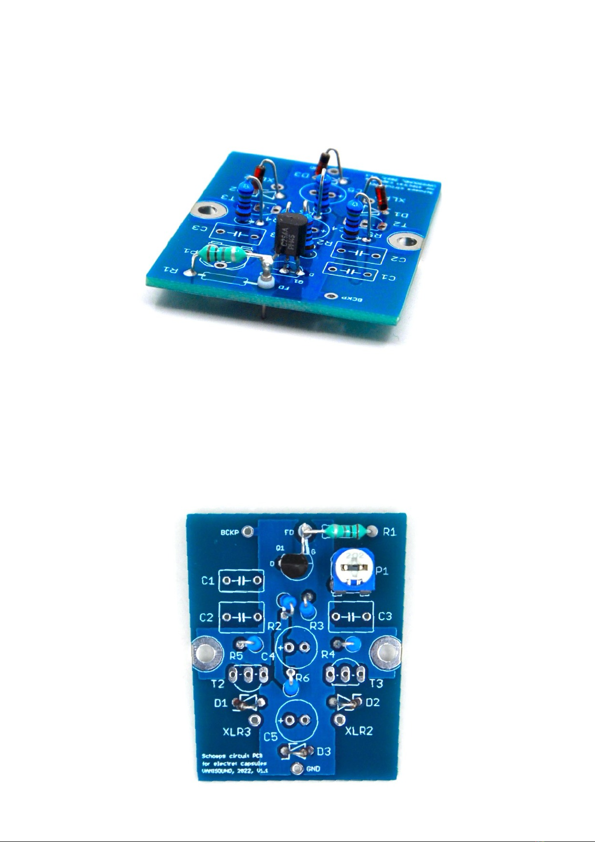
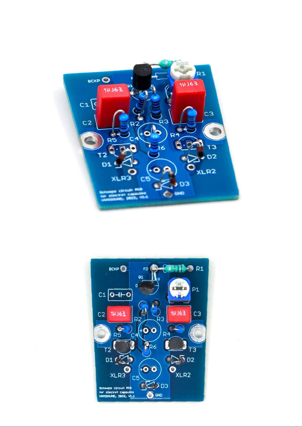
Continue by installing the FET transistor. I chose the original BC264, whose GATE leg is on its edge. If you
choose another FET, keep in mind that the GATE leg may be elsewhere. Always check this against the data sheet
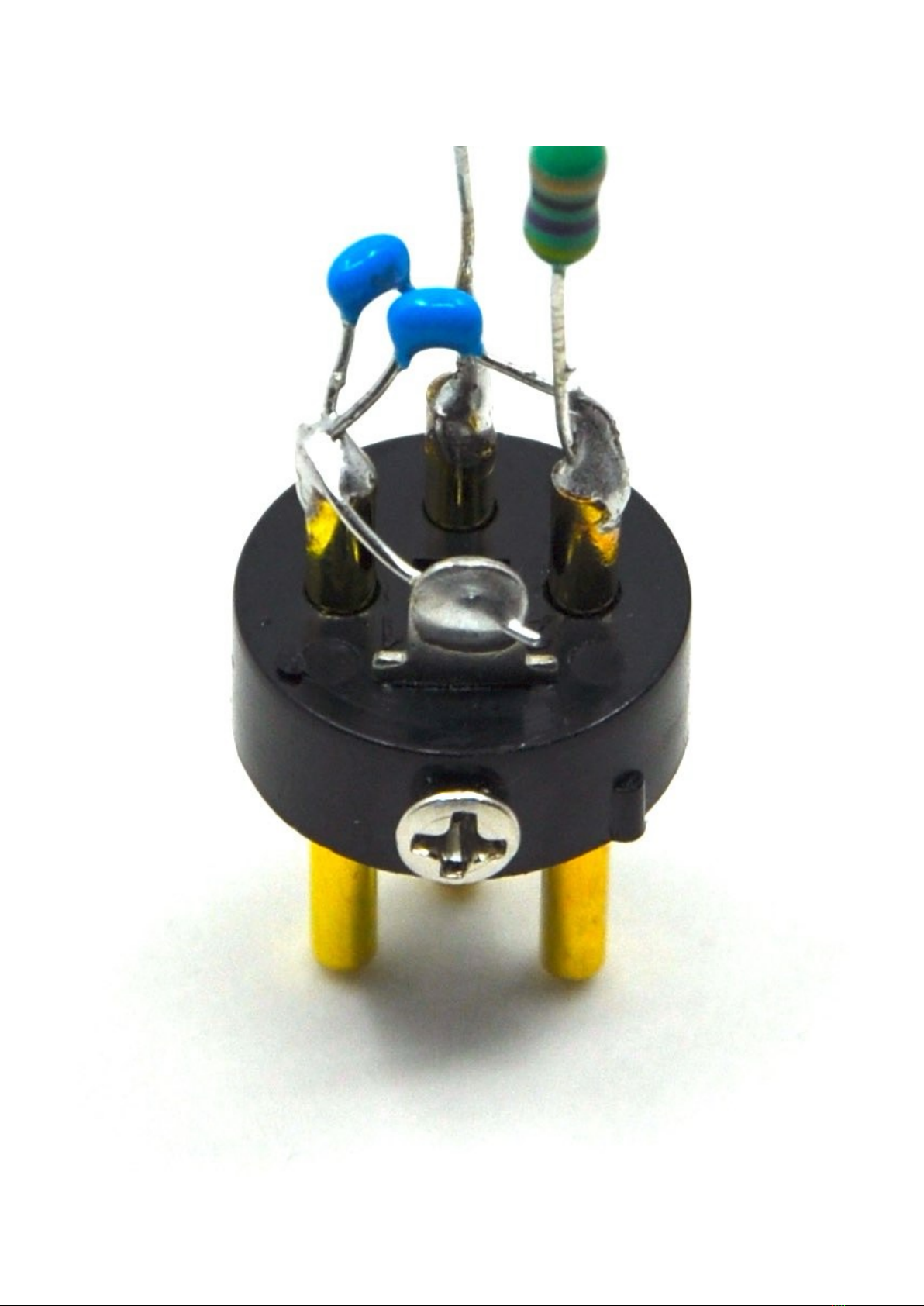
of the particular FET transistor. Note that the GATE leg is also soldered in the air to the teflon pin.
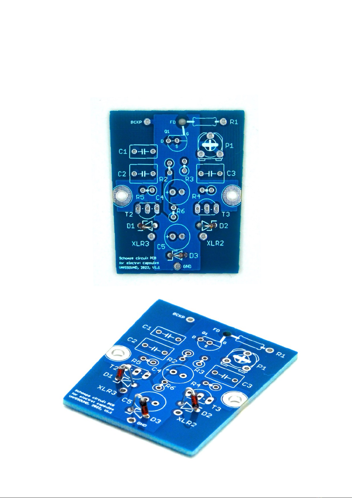
Notice that on the board around the footprint of the FET transistor there are small marks D, S and G (= drain,
source and gate). Make sure that the selected FET transistor uses the same footprints. If necessary, adjust
according to the markings on the board. Gate leg of FET transistor solder to teflon pin as if in air. Q1 pcb
footprint on the board match BC264 (original Schoeps FET) pin out. If you plan, for example, to use 2N3819 FET
tranzistor keep in mind that the GATE pin is the middle one (always check it against the FET transistor
datasheet).
Next up is P1 trimmer resistor near the FET transistor.

Now solder the two film capacitors. Note that the C1 position remains unoccupied. C1 forms the LPF for very
bright capsules. You can experiment with values of round 22nF if needed.
Continue with the installation of two transistors T2 and T3. Before that, match the HFE parameter on these
transistors. Most multimeters have a socket for the transistors and can therefore measure the base HFE
parameter.

Two electrolytic capacitors remain to be installed.
Clean the back of the board thoroughly with a brush and isopropyl alcohol to keep it perfectly clean and free of
soldering debris.

Now comes probably the most challenging stage of the build and that is installing the RF filter on the XLR
connector insert. Take two 2.2nF ceramic capacitors. Solder the first one between pin 1 of the XLR connector
insert and pin 2, and the second one between pin 1 and pin 3 of the XLR connector insert.
Then output two 47uH inductors from pin 2 and pin 3 of the XLR connector insert as seen in the photo.
Do not forget to connect pin 1 of the XLR connector to the ground loop (also located on the connector insert).


What must be added is that the microphone can function even without this filter. So there is nothing stopping
you from trying the microphone without it. In this case, just connect pin 1 of the XLR connector to the GND pad
on the board, pin 2 to the XLR 2 pad on the board and pin 3 to the XLR 3 pad on the board using a cable. If you
have a problem with signal interference, you can finish the filter later.
Now continue the build by screwing the XLR insert, electret capsule (without internal FET transistor), its stand
and board to the microphone chassis.
Solder the center terminal of the capsule to the teflon pin (red cable in the picture) and the remaining cable to
the pad named as BCKP on the board.
Also solder the protruding leg of the inductor leading from the XLR2 pin to the pad marked XLR2 on the board,
then do the same with the other inductor (from the XLR3 pin to the XLR3 pad on the board). Then solder the
last cable from the XLR1 pin to the GND pad on the board.
Here a detail of the XLR insert and its .

Put the head basket on the microphone and you can proceed to the first test of the microphone. Connect the
microphone via cable to the preamp and activate phantom power.
As for the P1 trimmer, set it so that you measure about 4.5V on the drain leg of the FET transistor and 6.1V
and the D5/R2 point. Please check the original schematic (Schoeps CMC3) for more info about operating
voltages.
Congratulations, your new microphone is now ready to serve in your studio!

WIRRING INFO
1) Electret capsule wiring: Center terminal cable to teflon pin marked as FD from the bottom side of pcb. Cable
from capsule backplate to BCKP pad on the mic pcb.
2) Its always great idea to check phase of DIY microphone against commercial microphone.
ADDITIONAL INFO
Take you time when soldering the XLR insert. You don't want to burn the plastic of the XLR insert. Take a break
while soldering the individual wires.

BILL OF MATERIAL
Part
Value
To l .
Min.V
olt.
Dimmensions
link 1
link 2
notes
Resistors
R1
1G
10 %
6.5x2.5mm
mouser link
R2
2K
1 %
6.3x2.4mm
mouser link
matched to R3
R3
2K
1 %
mouser link
matched to R2
R4
75K
1 %
mouser link
matched to R5
R5
75K
1 %
mouser link
matched to R4
R6
6K8
1 %
mouser link
P1
1M
20 %
tayda link
trimmer
Part
Value
To l .
Min.V
olt.
Dimmensions
link
type
notes
Capacitors
C1
22nF
50V
mouser link
film
forms LPF
C2
1uF
50V
mouser link
film
C3
1uF
50V
mouser link
film
C4
47uF
50V
mouser link
electrolytic
C5
220uF
16V
mouser link
electrolytic
C6
2.2nF
50V
mouser link
ceramic
filter on XLR
C7
2.2nF
50V
mouser link
ceramic
filter on XLR
Part
Value
To l .
Min.V
olt.
Dimmensions
link
type
notes
Diodes
D1
6.2V
mouser link
zener
D2
6.2V
mouser link
zener
D3
6.2V
mouser link
zener
Part

Inductors
L1
47uH
mouser link
filter on XLR
L2
47uH
mouser link
filter on XLR
Tranzistors
Q1
2N3819
mouser link
alternative BC264,
PCB footprint match
BC264 pin out
T2
BC559C
mouser link
alternatives: 2N5087,
BC560
HFE matched to T3
T3
BC559C
mouser link
alternatives: 2N5087,
BC560
HFE matched to T2
Other
Capsule
electret capsule without internal FET - two wire electret capsule
Teflon pin
mouser link
Value
To l .
Min.V
olt.
Dimmensions
link
type
notes
Part
Table of contents
Other VAMISOUND Network Hardware manuals
Popular Network Hardware manuals by other brands

Concept Pro
Concept Pro VUHDIPL-4 quick start guide

Dahua Technology
Dahua Technology NVR52A16-16P-4KS2 quick start guide

Proroute
Proroute H685 quick start guide

Extreme Networks
Extreme Networks IA-A-20 installation guide

Cabletron Systems
Cabletron Systems KBU64 Rackmount user manual

ERNITEC
ERNITEC DS-7700NXI-I/S quick start guide