Van Air Systems FP-4 Guide

PAGE 1
1.2 THIS KIT INCLUDES:
Control box
12'long heat tape, w/ thermostat
30'long roll of insulation wrap
Copper 1/2" NPT thermowell w/clip
Cord grip connector
Linear platinum sensor
2' of 3/8" flexible conduit
Three (3) seal fittings for connectors
3/8" conduit straight connector
3/8" 90 degree elbow connector
1" x 1/2" NPT bushing
Four (4) #12-14 x 1" self tapping screws
Heat Condictive Compound
February 2008
P/N 32-0228
REV.B
INSTALLATION, OPERATION & MAINTENANCE INSTRUCTIONS
FOR
FP-4 FREEZE PROTECTION KIT
P/N 83-0763
FOR TURBO-COOL AFTERCOOLERS
MODELS AC-140-7 thru AC-220-7
(230V-3PH-60Hz & 460V-3PH-60Hz)
WARNING
BEFORE STARTING INSTALLATION OR MAINTENANCE PROCEDURES, TURN OFF ELECTRICAL POWER AND
COMPLETELY DEPRESSURIZE THE AFTERCOOLER. FAILURE TO HEED THIS WARNING MAY RESULT IN SERIOUS
PERSONAL INJURY AND/OR DAMAGE TO THE UNIT.
NEVER REMOVE, REPAIR, OR REPLACE ANY ITEM ON THE AFTERCOOLER WHILE IT IS PRESSURIZED.
WHEN INSTALLING THIS KIT, ALWAYS COMPLY WITH THE NATIONAL ELECTRICAL CODE AND ALL OTHER
APPLICABLE FEDERAL, STATE AND LOCAL CODES.
SECTION 1 INTRODUCTION
1.1DESCRIPTIONOFOPERATION
The FP-4 freeze protection kit is designed to prevent aftercooler freeze up when the ambient temperature is near or below
freezing, 32oF (0oC).
The FP-4 has a two stage solid state temperature controller. The controller is mounted inside a Nema 4 enclosure. The
controller is used to energize a control relay which is rated to handle the load of the aftercooler fan at the various voltages.
The linear platinum temperature sensor and
thermowell mount into the piping between the
outlet manifold of the aftercooler and the
separator. When the temperature of the com-
pressed air system at the aftercooler outlet falls
to 35OF, the controller will automatically turn off of
the fan. The controller is set for a 10oF dead
band to prevent rapid cycling (fan will turn off at
35OF and on at 45oF).
A 12 foot heat tape and 30 feet of insulation wrap
are provided to wrap around the separator. The
heat tape is equipped with its own internal
temperature control. The heat tape and insula-
tion will provide additional freeze up protection.
FIGURE 1-A ITEMS INCLUDED WITH THIS KIT
1.
2.
3.
4.
5.
6.
7.
8.
9.
10.
11.
12.
13.

PAGE 2
2.1MOUNTINGTHECONTROLBOX
The control box should be mounted near the
outlet manifold of the aftercooler. Make sure
that the control box is close enough so that all
components can reach the box when in-
stalled.
Drill the four pilot holes in the mounting
surface using a 1/8" drill. Reference Figure 2-
A for dimensions.
The control box will be mounted with the
hinged side of the enclosure on the bottom.
Fasten the controller in place using the four
(4) #12-14 x 1" long self-tapping screws
supplied with the kit.
SECTION 2 INSTALLATION
FIGURE 2-A MOUNTING THE CONTROL BOX
FIGURE 2-B MOUNTING THE THERMOWELL
FIGURE 2-C INSTALLING THE HEAT TAPE AND INSULATION
2.2INSTALLING THESENSOR AND
THERMOWELL
A 1/2" NPT or larger connection in the system
piping between the outlet of the aftercooler
and the inlet of the separator is required for
the thermowell and sensor.
Thread the thermowell and the 1" x 1/2"
bushing (if required) into a connection
between the aftercooler outlet and the
separator.
Place some heat conductive compound into
the thermowell. Place the sensor into the
thermowell and fasten it in place using the
clip supplied with the thermowell. Reference
Figure 2-B.
Install the cord grip connector into the control
box as shown in Figure 2-B. Push the sensor
cable through the connector. Wire the sensor
cable to the controller circuit board terminals
as shown in Figure 2-F. Tighten the grip nut
on the connector.
2.3 INSTALLING THE HEAT TAPE AND
INSULATION
Install the cord grip on the control box as
shown in Figure 2-C.
Cut the plug end off the heat tape. Strip back
the wires.
Push the wire end of the heat tape through
the connector. Allow enough cord inside the
box for wiring. Connect the heat tape to the
proper terminals in the control box as shown
in FIGURES 2-F. Tighten the grip nut on the
connector.
Run the heat tape to the separator. Wrap the
heat tape around the separator as shown in
Figure 2-C. Do not overlap the tape.
Wrap the insulation around the piping and
heat tape as shown in Figure 2-C.

PAGE 3
SECTION 2 INSTALLATION
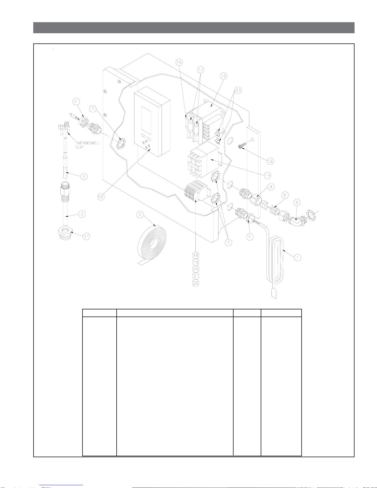
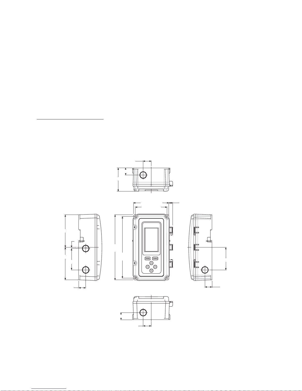
2.4 INSTALLING THE CONDUIT
Install the straight conduit connector
on the control box. Reference Figure
2-D.
The supplied conduit will be used to
run between the aftercooler and the
control box. Connect the conduit to
the straight connector.
Install the 90 degree elbow connector
on the aftercooler. Reference Figure
2-D.
FIGURE 2-D INSTALLING THE CONDUIT
2.5 INSTALLING THE TRANSFORMER JUMPERS
WARNING
BEFORE STARTING THIS PROCEDURE, TURN OFF
ELECTRICAL POWER. FAILURE TO HEED THIS
WARNING MAY RESULT IN SERIOUS PERSONAL
INJURY AND/OR DAMAGE TO THE UNIT.
This kit was designed to operate at 230V-3PH-60Hz or
460V-3PH-60Hz. Two jumpers were shipped inside the
control box. They must be installed on the transformer
before connecting the power to the control box. Install the
jumper(s) as shown in Figure 2-E for the desired voltage.
CAUTION
It is important that this procedure be properly
completed before continuing with installation.
This kit will not operate without the jumpers.
Damage to the control box will occur if the jumpers
are improperly installed.
FIGURE 2-E INSTALLING THE TRANSFORMER JUMPERS
2.6 ELECTRICALCONNECTIONS
WARNING
BEFORE STARTING INSTALLATION PROCEDURES
OR ATTEMPTING TO MAKE ANY WIRING CHANGES,
TURN OFF ELECTRICAL POWER. FAILURE TO HEED
THIS WARNING MAY RESULT IN SERIOUS
PERSONAL INJURY AND/OR DAMAGE TO THE UNIT.
WHEN INSTALLING THIS KIT ALWAYS COMPLY WITH
THE NATIONAL ELECTRICAL CODE AND ALL OTHER
APPLICABLE FEDERAL, STATE AND LOCAL CODES.
A 7/8" hole in the top right side of the control box is provided
for incoming power conduit. The hole can be enlarged if
necessary.
The control box is designed for 230V-3PH-60Hz or 460V-
3PH-60Hz operation. The transformer jumpers must be
installed as outlined in Section 2.5 for the desired voltage.
Make the necessary wiring runs and connections for the
main power supply.
Remove the junction box cover on the aftercooler for access
to the junction box. Make the necessary wiring runs through
the conduit from the aftercooler to the control box. Fasten the
conduit to the connector on the aftercooler. Reference
FIGURE 2-D.
Make the wire connections at the junction box on the
aftercooler. Reference FIGURE 2-F. Fasten the junction box
cover to the aftercooler.
Complete the wire connections inside the controller as
shown in FIGURE 2-F.
Once all wiring connections have been properly made, the
rotation of the fan should be checked. The fan must rotate in
the proper direction for maximum performance. Reference
the operator's manual supplied with the aftercooler for the
correct rotation direction. Also, check the aftercooler for a
rotation direction label.
To check the rotation, turn on the power supply to the
aftercooler. If the fan does not rotate in the proper direction,
any two of the power leads to the motor can be switched.

PAGE 4
IMPORTANT
THE FAN MOTOR MUST ROTATE IN THE CORRECT DIRECTION. REFERENCE THE AFTERCOOLER
OPERATOR'S MANUAL FOR PROPER ROATION DIRECTION. IF IT DOES NOT, THE ROTATION CAN BE
CORRECTED BY SWITCHING TWO OF THE POWER LEADS TO THE MOTOR.
SECTION 2 INSTALLATION
FIGURE 2-F CONTROL BOX COMPONENT LAYOUT and WIRING DIAGRAM

PAGE 5
SECTION 2 INSTALLATION
2.7 SETTINGTHECONTROLLER
The controller was factory set for normal operation. The
factory settings are as follows: RELAY 1
SETPOINT 35OF
DIFFERENTIAL 10OF
MODE COOLING
Turn on the main power to the FP-4 control.
If the settings have been changed, set them to the factory
settings following the procedures below . The controller will
retain the setting if the power is disconnected.
PROGRAMMING PROCEDURES
1. Press MENU key, then press RIGHT arrow key three
times. Use the UP and DOWN arrow to select the
SETPOINT. Press the RIGHT arrow to store the setpoint in
memory.
2. Press the RIGHT arrow to set the DIFFERENTIAL. Use
the UP and DOWN arrow to set the differential. Press the
RIGHT arrow to store the differential in memory.
3. Press the RIGHT arrow key to set the HEATING / COOL-
ING mode. Use the UP or DOWN arrow to select the
desired mode. Press the RIGHT arrow to store the mode in
memory.
4. Press RIGHT arrow three times to exit the program mode.
SECTION 3 OPERATION
3.1 OPERATION
Once the kit is installed and set properly, just energize the
controller and it will operate automatically.
The controller will turn off half of the aftercooler fan when the
temperature of system air at the outlet of the aftercooler falls
to 35OF. The fan will turn on when the system temperature
rises to 45oF. Reference chart in Figure 3-A .
The heat tape is controlled by its own internal thermostat.
Power is supplied to the heat tape as long as the control box
is energized.
The temperature controller is equipped with a LCD display.
During normal operation when the fan are operating,
(temperature above set points) the sensor temperature and
RELAYS 1 ON will be displayed on the controller.
NOTE: The cover on the control box must be opened to view
the temperature controller display.
FIGURE 3-A OPERATION SEQUENCE
FIGURE 2-G CONTROLLER DISPLAY
Table of contents
Other Van Air Systems Accessories manuals