PLEASE NOTE: Every effort is made for Vance & Hines Exhaust Systems to provide improved cornering clearance. However, due to design and space limitations on some motorcycle models,
ground and cornering clearance may not be improved and in some cases may be reduced. Be sure to follow proper installation instructions.
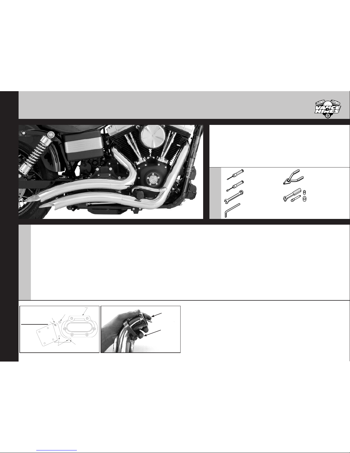
VANCE & HINES EXHAUST SYSTEM
INSTALLATION
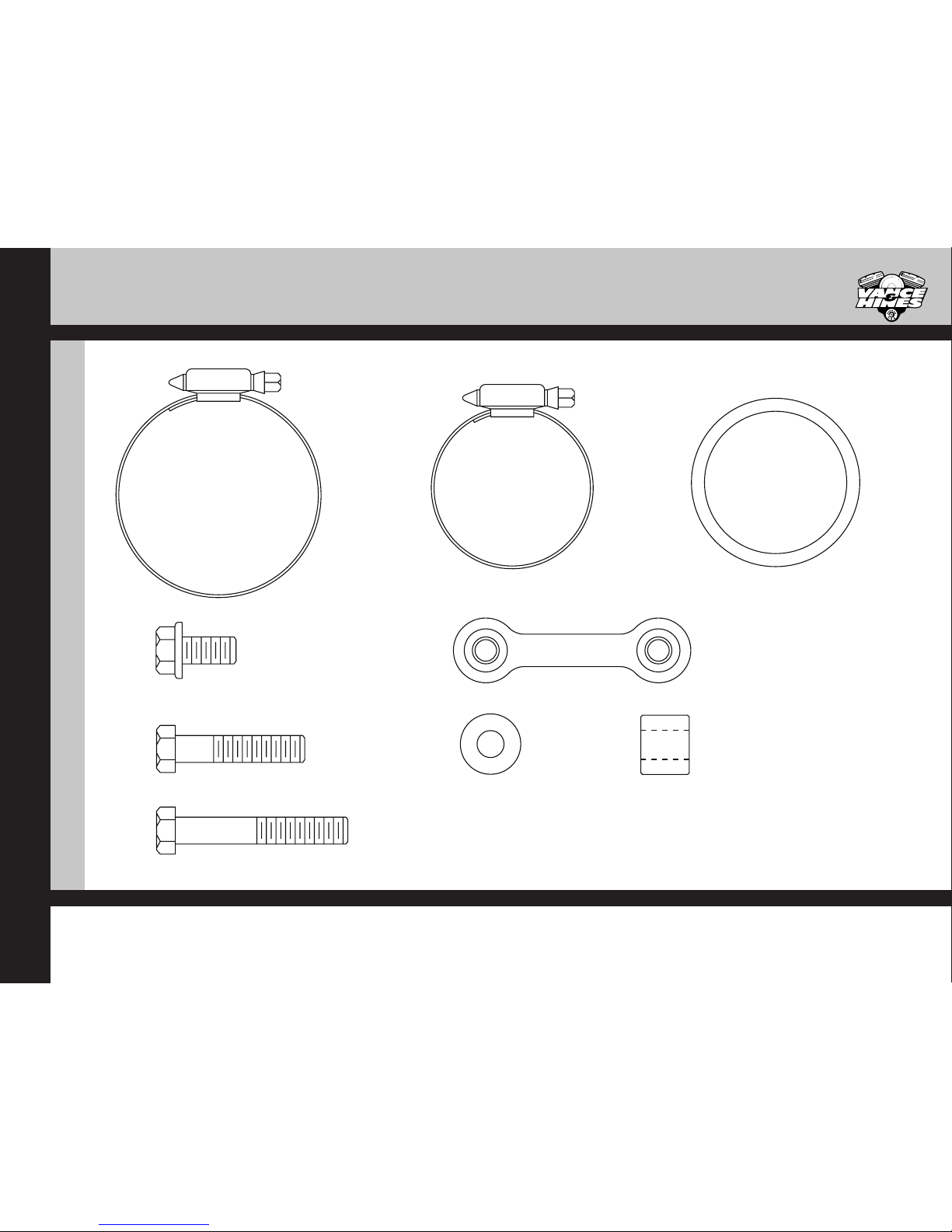
1. Attach mounting bracket 390-P to transmission and tighten to 12-15 Ft/Lb
torque. (Figure 1). NOTE: 2006 to 2007 models use three 5/16” x 1-1/2” hex
head bolts and washers. 2008 to 2011 models use three 5/16” x 1-1/2” hex
head bolt, washers, 11/16” spacer between the bracket and transmission in
top hole. 2012 and later models use one 5/16” x 2” hex head bolt, washers
11/16” spacer in top hole and two 5/16” x 1-1/2” hex head bolts and
washers in remaining holes.
2. Remove head pipes from their protective packaging and install circlips and
anges from the stock system onto both new head pipes (Figure 2).
3. Apply a small amount of anti-seize compound to the threads of the oxygen
sensors and install them into the new head pipe.
NOTE: 2006 to 2011 models or models using 18mm wideband oxygen sensors
install sensor directly into head pipe. 2012 to later models install supplied
18mm to 12mm oxygen sensor adapter then install 12mm oxygen sensors
(Grey connector into front head pipe, Black connector into rear head pipe.)
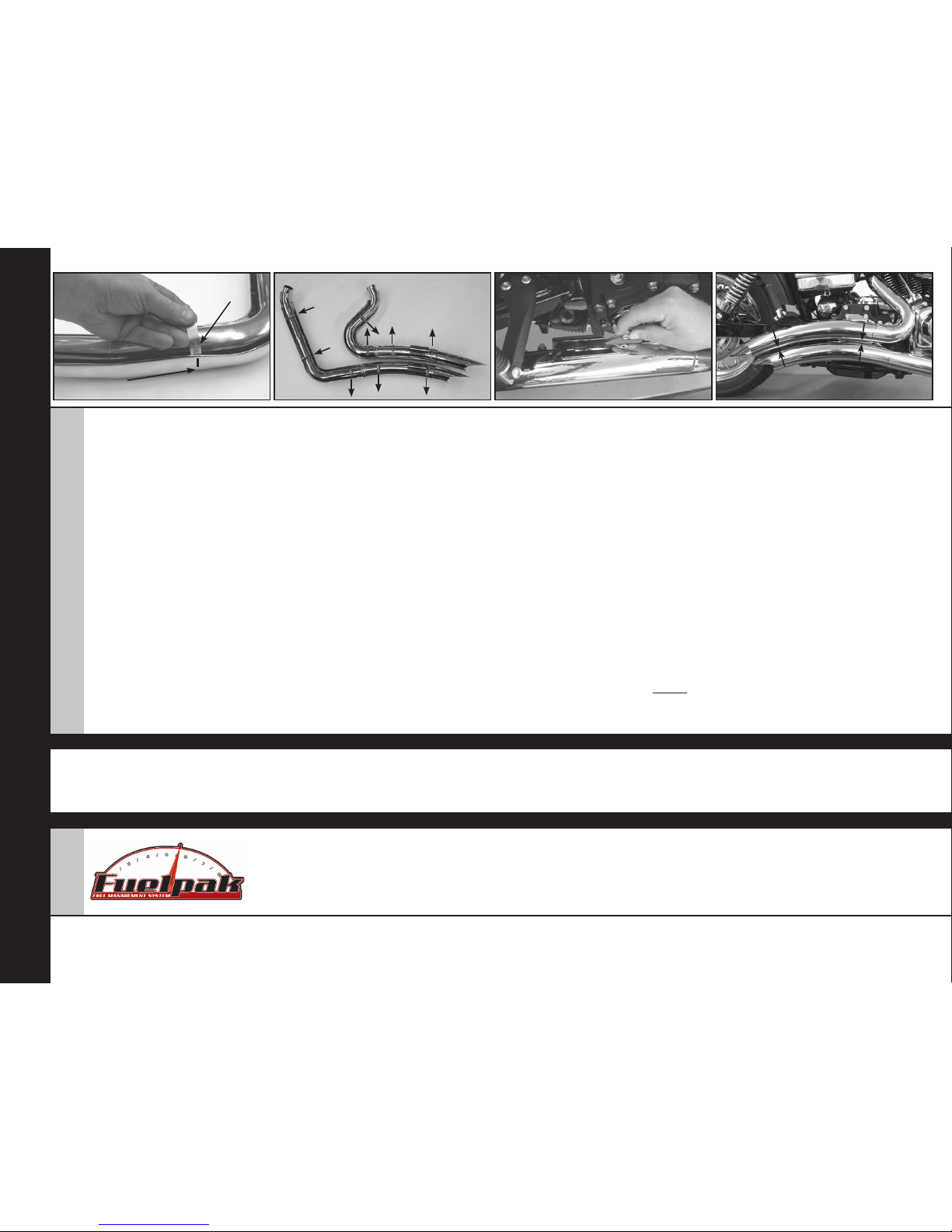
4. Remove heat shields from their protective packaging. Place each heat
shield on a non-abrasive surface such as a blanket or carpet. Using a felt tip
pen, mark outside edge of each heat shield to show location of hose clamp
mounting clips (Figure 3).
5. Lay head pipes (D418FC & D419FC) into head pipe heat shields (D400HC
& D403HC) respectively. Make sure alignment clip on head pipe ts inside
heat shield. Loosely install #20 hose clamps by feeding tail end of clamp
into heat shield clips (Figure 3). Take note of screw head direction (Figure 4).
Screw head should be accessible when system is installed on motorcycle for
adjustment purposes. NOTE: Do not tighten at this time.
6. Using stock ange nuts, carefully install head pipes into exhaust ports, starting
with the rear cylinder. Assistance may be required. NOTE: Do not tighten at
this time.
7. Slide nutplates inside brackets that are welded to backside of each mufer
body (Figure 5). While holding nutplates in place, attach mufer bodies to
mounting bracket 391-P using four 5/16”x 5/8” ange head bolts (supplied).
Leave them loose at this time.
8. Align pipes on motorcycle so that the gap between the two mufer bodies is
consistent from front to rear and tighten exhaust port ange nuts (Figure 6).
9. Tighten ange bolts securing mufer bodies to mount bracket 391-P.
10. Using the #28 hose clamps install the mufer heat shields with the D308HC on
the front head pipe and the D309HC on the rear. Take note of screw head
direction (Figure 4). NOTE: Do not tighten at this time.
11. Adjust the heat shields to get the best alignment at the seam where they
touch (Figure 6) and tighten all the hose clamps.
12. Feed wire for front oxygen sensor through frame and into plastic holder on
frame. Plug sensor into stock wiring connector. Snap plastic holder closed to
hold connector in place.
13. Put toothed edge of wiring holder into slot in frame. Re-install rectier so that
it ts under tooth of wiring holder, keeping it in place in frame. Tighten both
bolts.
14. Feed connector for rear oxygen sensor through frame and into underseat
compartment. Plug sensor into stock wiring connector.
15. Re-install seat.
16. Check for adequate clearance between all exhaust system components
and motorcycle accessories prone to heat damage.
17. Be sure to tighten all hardware before starting your motorcycle.
18. After installation and
before
starting motorcycle, completely clean pipes
and mufers with warm soapy water and a clean soft cloth that will not
leave a residue. NOTE: Any residue, oil, or ngerprints will stain the chrome
when the metal heats up.
EXHAUST CARE - HELPFUL HINTS TO AVOID DISCOLORATION OF EXHAUST SYSTEM
FIGURE 3 FIGURE 4 FIGURE 5 FIGURE 6
D942IN Rev. 1.0Page 2 of 4
Installing
hose clamp
Mark outside
edge
Arrows indicate clamp
screw head direction
Installing nutplate Align gap between mufers
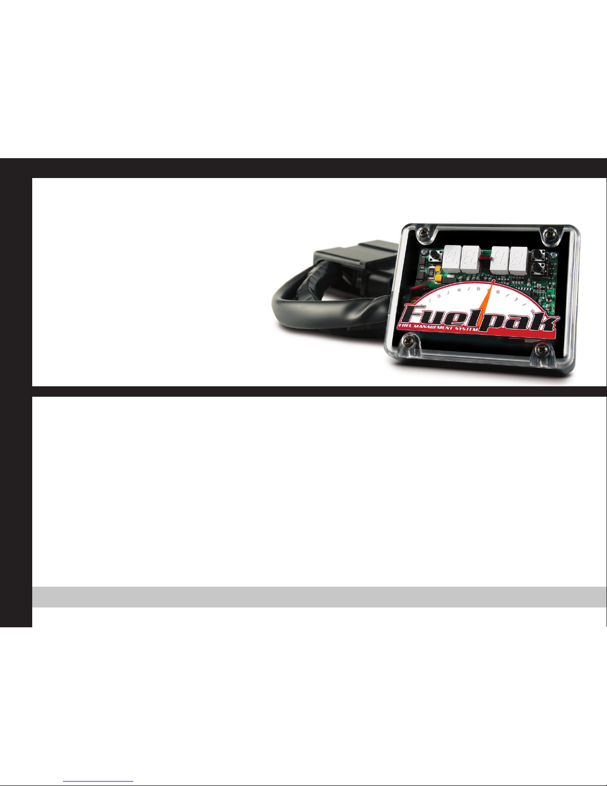
FUELPAK
MORE POWER : LESS NOISE
1. When installing a new set of chrome pipes, make sure your hands are clean and free
of oil. After installation, thoroughly clean pipes with warm soapy water and a soft
cloth. Dry with clean towel to remove any residue (chrome wax / polish, glass cleaner,
alcohol, ammonia, etc...) before starting the motorcycle.
2. Avoid long periods of idling as this can cause discoloration.
3. Intake leaks can cause the engine to run lean and overheat, this could lead to
discoloration.
4. Make sure there are no exhaust leaks at the junction of the exhaust pipes and cylinder
head. We recommend replacing gaskets if they are worn.
VANCE & HINES OPTIONAL ACCESSORIES
FUEL MANAGEMENT:
Take the guess work out of fuel injection with Fuelpak Fuel
Management. Contact your local dealer or call (562) 921-
0071 to order. Visit fuelpak.com for more information.
Fuelpak is intended for racing or off-highway use only,
and is not legal for sale or use in California on pollution-
controlled vehicles.