Vanderbilt CHSM2210-B User manual

CHSM2210/2211-B
Medium Camera Housing with
Integrated Bracket
Installation Guide

© Vanderbilt 2016
2
Data and design subject to change without notice. / Supply subject to availability.
© 2016 Copyright by Vanderbilt
We reserve all rights in this document and in the subject thereof. By acceptance of the document the recipient acknowledges these rights
and undertakes not to publish the document nor the subject thereof in full or in part, nor to make them available to any third party without our
prior express written authorization, nor to use it for any purpose other than for which it was delivered to him.

© Vanderbilt 2016
3
Contents
1Safety .......................................................................................................5
1.1 Target group..............................................................................................5
1.2 General safety precautions.......................................................................5
1.3 Meaning of the signal words .....................................................................6
1.4 Meaning of the hazard symbols................................................................6
2EU Directives...........................................................................................7
3Technical data .........................................................................................8
3.1 Specifications............................................................................................8
3.2 Mechanical dimensions.............................................................................9
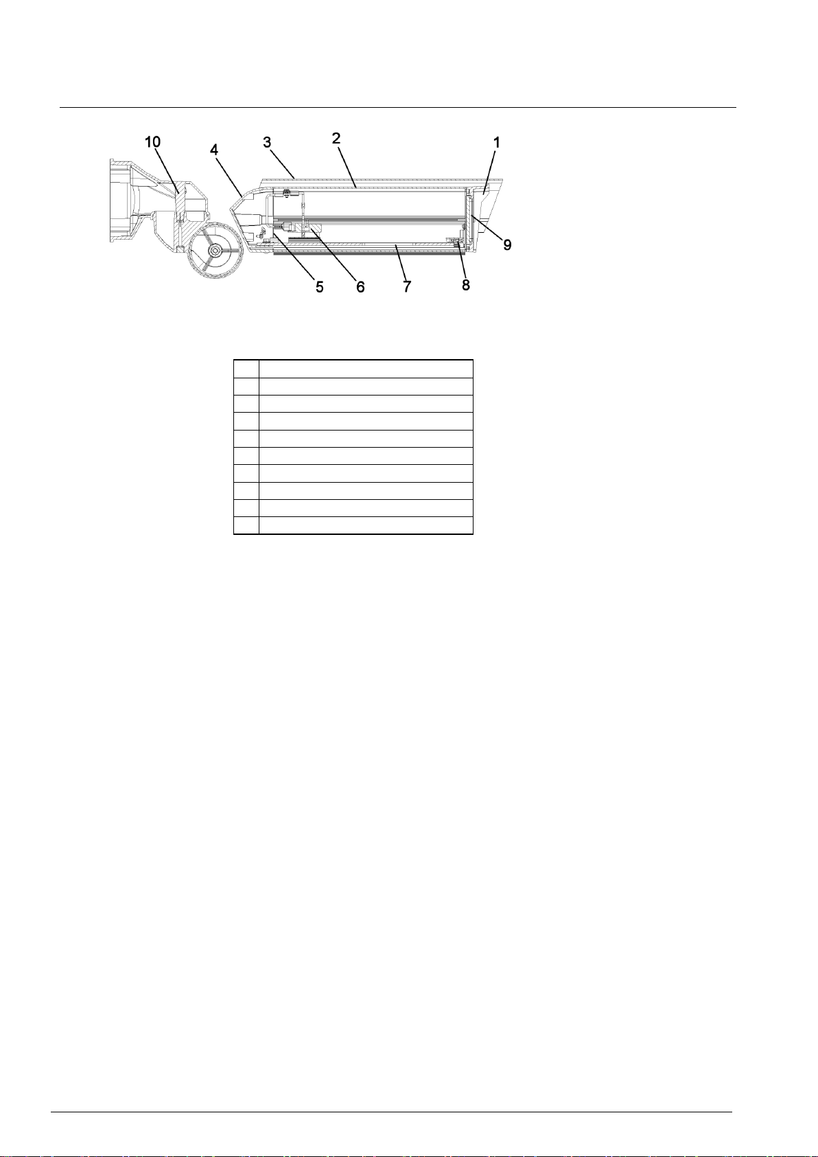
3.3 Key to parts.............................................................................................10
4Package contents..................................................................................11
5Installation .............................................................................................12
5.1 Accessing the inside of the housing enclosure.......................................12
5.2 Fitting the accessories ............................................................................13
5.2.1 Power supply modules............................................................................13
5.2.2 Ceiling mount bracket .............................................................................14
5.3 Fitting the camera and lens.....................................................................15
5.4 Mounting the camera housing assembly ................................................16
5.5 Connecting to the power supply..............................................................18
5.6 Adjusting the sunshield...........................................................................19
6Maintenance and service .....................................................................20
7Disposal .................................................................................................20

© Vanderbilt 2016
4

Safety
© Vanderbilt 2016
5
1 Safety
1.1 Target group
The instructions in this document are designed only for the following target group.
Target readers
Qualification
Activity
Condition of the
product
Installer
Technical training for
building or electrical
installations.
Installs the product,
individual components
of the product or
replacement parts.
Components of the
product are not yet
installed or need to be
replaced or modified.
1.2 General safety precautions
Read the general safety precautions before operating the device.
Follow all warnings and instructions marked on the device.
Keep this document for reference.
Always pass this document on together with the product.
Please also take into account any additional country-specific, local safety
standards or regulations concerning project planning, operation and disposal of
the product.
It is recommended that all preparatory work (e.g. fitting of accessories) be
carried out in a workshop prior to final installation.
Liability claim
Do not connect the device if it is damaged or any parts are missing.
Do not make any changes or modifications to the device unless they are
expressly mentioned in this manual and have been approved by the
manufacturer.
Use only spare parts and accessories that have been approved by the
manufacturer.
Risk of failure due to incorrect installation
The fuse for the device and the fuse for the electrical system of the building must
be installed separately.
Risk of cable damage due to stress
Use only cable types that are approved for the environmental requirements.
The cable glands used must be appropriate for the cable diameter.

Safety
© Vanderbilt 2016
6
1.3 Meaning of the signal words
The severity of a hazard is indicated by the following written warning notices.
Signal word
Type of risk
CAUTION
There is a risk of minor to medium injuries or damage to property
IMPORTANT
Malfunctioning may result
1.4 Meaning of the hazard symbols
The nature of the hazard is indicated by icons.
Warning of a hazard

EU Directives
© Vanderbilt 2016
7
2 EU Directives
The product complies with the requirements of the following EU directives. The EU
declaration of conformity is available from:
Vanderbilt
Clonshaugh Business and Technology Park
Clonshaugh
Dublin 17
Ireland
www.vanderbiltindustries.com
European Directive 2004/108/EC „Electromagnetic Compatibility”
Compliance with the European Directive 2004/108/EC has been proven by testing
according to the following standards:
Emitted interference:
EN 61000-3-2
EN 61000-3-3
EN 55022 Class B
Resistance to interference:
EN 50130-4
European Directive 2006/95/EC „Low-Voltage Directive”
Compliance with the European Directive 2006/95/EC has been proven by testing
according to the following standard:
Safety:
EN 60950-1

Technical data
© Vanderbilt 2016
8
3 Technical data
3.1 Specifications
Nominal Voltage
CHSM2210-B: 110 –230 V AC 50/60 Hz
CHSM2211-B: 12 –24 V AC 50/60 Hz
Fuse Rating (Fuse F1)
CHSM2210-B: 2 A 250 V AC 5 x 20 Type (T), HBC
CHSM2211-B: 5 A 250 V AC 5 x 20 Type (T), HBC
Electrical Connections
Main supply connections via fused PCB mounted terminal blocks.
Use crimped ferrules when terminating cables.
6 way pillar terminal block available for user connections.
Cable Entry
2 x 16 mm Cable Glands (5 –10 mm diameter cable range)
Heater
7 W nominal, 25 W max.
PTC resistor heating element, thermostatically controlled.
Environmental
Operating Temperature
-20 to +60 °C
Ensure fitted equipment has suitable temperature range for the
application (e.g. maximum typical ambient operating temperature of
camera and lens. Ta = 40 °C).
Maximum internal dissipated power
30 W
Relative humidity
Up to 95 % non-condensing
Ingress Protection
IP66 BS EN 60529
Material
Toughened Glass Window
Aluminium extrusions (Housing body / Sunshield)
Die cast aluminium (front and rear end caps/bracket)
Finish
Endcaps: Polyester powder coat, RAL7016 Grey
Housing Body: Polyester powder coat, RAL9006 White Aluminium
Sunshield: Polyester powder coat, RAL9006 White Aluminium
Internal Dimensions (L x W x H)
300 x 85 x 85 mm
Weight
3.5 Kg

Technical data
© Vanderbilt 2016
9
3.2 Mechanical dimensions
Fig. 1 Mechanical dimensions
1
Diameter 133 mm
11
574 mm
2
169 mm
12
17°
3
458 mm
13
108° without tilt
4
133 mm
14
108 mm
5
76 mm
15
504 mm
6
66 mm
16
547 mm
7
125 mm
17
113°
8
3 mm
18
108° without tilt
9
163 mm
19
108 mm
10
127 mm
20
504 mm

Technical data
© Vanderbilt 2016
10
3.3 Key to parts
Fig. 2 Key to Parts
1
Front End Cap
2
Housing Body
3
Sunshield
4
Rear End Cap
5
Cable Glands
6
Terminal Board
7
Camera Mounting Plate
8
Demister Assembly
9
Window
10
Bracket Assembly

Package contents
© Vanderbilt 2016
11
4 Package contents
Camera housing assembly
Installation Guide
Camera fixing screw (1/4” BSW x ½” hex hd.)
Camera fixing screw (1/4” BSW x ¾” hex hd.)
Spacer block (1.6 mm thick)
Spacer block (3 mm thick)
2.5 mm (across flats) ALLEN Key, long reach.
6 mm (across flats) ALLEN Key.
Camera plate insulator
Shoulder washer (to insulate screw from camera mounting plate)
NOTE
The complete assembly should be mounted and tested in the workshop prior to use on-site.
Accessories
Type
Designation
CAPD1210-C230
12 V DC 500 mA PSU 230 V AC input
CHBA-221X-B
Ceiling Mount Bracket

Installation
© Vanderbilt 2016
12
5 Installation
5.1 Accessing the inside of the housing enclosure
1. Undo the two M4 captive screws that secure the housing cover to the rear
cap/bracket assembly and slide the housing cover forward slightly.
2. Disconnect the earth wire from the termination board.
3. Slide the housing cover forward towards the front of the camera mounting
plate, until it hinges downward (see Fig. 3).
4. If required, you can remove the housing cover from the camera mounting
plate by twisting it slightly and withdrawing it from the hinge pins.
NOTE
To re-assemble carry out steps 1 to 4 in reverse, making sure the earth wire is reconnected. The two
M4 screws which secure the housing to the rear cap should be retightened to a torque of 2 Nm.
Fig. 3 Inside the housing enclosure
1
Sun Shield
2
Demister
3
Termination Board
4
Rear Cap
5
Camera Mounting Plate
6
Housing Cover

Installation
© Vanderbilt 2016
13
5.2 Fitting the accessories
5.2.1 Power supply modules
In some installations the camera requires a 12 V DC power supply; Vanderbilt
power supply module CAPD1210-C230 is available and mounts inside the rear end
cap (see Fig. 4). It is fused by connecting it through the terminal board. To fit the
module:
1. Secure the module in the rear end cap using two M3 screws and lock washers
(see Fig. 4), taking care not to trap any cables.
Fig. 4 Power supply module
1
12 V DC Power Supply Module
2
M3 Screws
2. Cut the module’s input cables (brown/blue) to a suitable length and connect
them to the termination board’s “Fused Output” terminals (brown –live; blue –
neutral). See section 5.5 for terminal board details.
3. Connect the module’s output cable to the camera supply terminals after fitting
the camera (White stripe or ribbed stripe –positive, +12 V DC; black –
negative, 0 V.). Use suitable cable clips (not supplied, see Fig. 5).

Installation
© Vanderbilt 2016
14
Fig. 5 Power supply module cable routing
1
12 V DC power supply module
2
Suitable cable clip (not supplied)
3
PSU module output cable to camera supply terminals
4
PSU module input cable
5
‘Fused output’ terminals
IMPORTANT
Ensure all SELV and signal wiring is kept away from live parts and is suitably
protected from live parts by double insulation.
5.2.2 Ceiling mount bracket
A ceiling mount bracket CHBA-221X-B is available for the housing which rotates
the mounting surface by 90 degrees to allow mounting onto a ceiling. An
installation instruction is supplied with the bracket.

Installation
© Vanderbilt 2016
15
5.3 Fitting the camera and lens
The camera should be mounted so that the lens is aligned with the centre of the
housing window and as close to the window as possible.
1. With the slots aligned, fit the self-adhesive camera plate insulator to the
camera plate (see Fig. 6).
2. Position the camera at the required height by placing the appropriate spacer
blocks between the mounting plate and the camera. Note that two thicknesses
of spacer are supplied.
3. Place the supplied shoulder washer through the slot in the camera mounting
plate from the bottom up, and then feed the mounting screw through the
washer and spacer blocks and screw into the camera mounting.
4. Adjust the camera position before you fully tighten the mounting screw.
5. Connect power to the camera as described in Section 5.6.
6. Terminate and connect the necessary video signal cable to the camera
(e.g. coax cable).
Fig. 6 Fitting the camera and lens
1
Camera
2
Spacer block
3
Camera plate insulator
4
Adjustment location slot
5
Shoulder washer
6
Mounting screw (1/4 BSW) 1/2” or 3/4”

Installation
© Vanderbilt 2016
16
5.4 Mounting the camera housing assembly
The bracket has a set of 4 through holes suitable for M8 screws on a 101.6 mm
(4”) PCD for mounting the assembly to a surface or bracket. The holes are part of a
casting, and are 35 mm deep, which needs to be taken into account when
specifying screw lengths.
1. Separate the three sections of the mounting bracketry by undoing the 2 x M6
Cap Head screws.
2. Remove the gland plate on the rear cap to allow ease of installation. Do this
by loosening the bottom two screws in the plate, undoing the captive top
screw and lifting out.
3. If required, drill and fit cable glands (28 mm maximum outside diameter) to the
top or bottom of the wall or ceiling bracket section. Cables can be fed directly
through the mounting surface into the bracketry.
4. Attach the wall bracket to the mounting surface using suitable fixings. A spirit
level should be used to ensure that the fixing is level.
IMPORTANT
Ensure that the correct bracket for the application is used and that it is securely
mounted to the prime surface.
Ensure the surface to which the unit is being mounted is solid and that there is
no risk of the bracket becoming loose due to crumbling brick or mortar.
Ensure that all fixing screws are suitable for the application and securing bolts
are tight. Where required fit suitable anti-vibration fastenings.
5. Feed the cables or conduit (16 mm maximum) through the wall bracket and
centre section then attach the centre section to the wall bracket. Repeat this
with the rear end-cap section. Secure but do not tighten the two M6 cap head
screws which hold the sections of bracket together. Ensure that the toothed
lock washers are still in place.
6. Feed the cables through the gland plate hole and refit the gland plate, passing
the cables through the appropriate gland and tightening correctly to ensure a
weatherproof seal. If conduit is used, replace the gland with the appropriate
conduit fixing.
7. Before connecting the cable(s), move the housing through its full range of
horizontal and vertical movement, mark the cable length at its greatest
extremity. Cut the cable(s) at a suitable length to terminate. This will ensure
that the cable is of sufficient length if the housing is repositioned at a later
date. There must be no connection terminals within the mounting bracket.
8. Make sure that the cables are not snagged or trapped anywhere inside the
mounting bracketry and that the cables were not damaged during the
installation.
9. Connect the power input as detailed in section 5.5, terminate and connect any
other cables as necessary (e.g. Coax cable to camera).
10. Move the camera housing to the required position and tighten the two M6 Cap
Head screws to fix in position. It is important to ensure that the toothed lock
washers are still in place after installation.
11. Refit the housing cover as described in section 5.1.

Installation
© Vanderbilt 2016
17
Fig. 7 Mounting the Camera Housing Assembly
1
2 16 mm gland (for 5 –10 mm diameter cables)
2
Rear end-cap section
3
Wall bracket section –replace with ceiling mount option (CHBA-221X-B) if required
4
Sections are held together with 2 M6 screws and 2 x toothed lock washers
5
Centre section
6
Flat area top and bottom
7
4 8.5 mm diameter through holes on a 4“ (101.6 mm) PCD

Installation
© Vanderbilt 2016
18
5.5 Connecting to the power supply
IMPORTANT
Please read the ‘Safety’ section on page 5 before connecting to the Power
Supply.
IMPORTANT
Take care not to damage the cables during installation.
All wiring must be installed to local and national standards. Ensure all SELV
and signal wiring is kept away from live parts and is suitably protected from
live parts by double insulation.
CAUTION
A readily accessible all-pole disconnect device with at least 3 mm contact
separation shall be incorporated in the building installation wiring. As part of the
building installation, protect the unit via a fuse or circuit breaker rated at 2 A for
CHSM2210-B 110 –230 V AC units and 5 A for CHSM2211-B 12–24 V AC
units.
NOTE
Use only cable suitable for the application and that meets the standards required by the installation.
The conductor size for power cable(s) must be at least 0.75 mm2. The maximum recommended
conductor size is 1.5 mm2.
1. The two glands supplied are suitable for cables with a diameter of 5 –10 mm;
remove the blanking plug supplied in the chosen gland. It is important that the
correct sized glands are used for the cable utilised to ensure a weatherproof
seal.
2. Insert the power supply cable through the selected gland having fed it through
the bracketry and cut to length as described in section 5.4.
3. Connect the power cable to the terminal board in the “Input supply terminal”
indicated in Fig. 8, it is recommended to use crimp ferrules on the cores.
4. It is possible to move the terminal board assembly along the camera mount
rail. Loosen the M3 screw and move the assembly, then retighten the screw.
Indicator
Description
L
Live (Brown)
N
Neutral (Blue)
E
Earth (Green/Yellow)
Fig. 8 Terminal board connection details
1
Ancillary Connections Block
2
Fused Output
3
Earth (Gnd)
4
Input Supply Terminal
5
Fuse F1
2 A 250 V AC 5x20 Type (T), HBC for T462 (230 V AC)
5 A 250 V AC 5x20 Type (T), HBC for T463 (24 V AC)
6
Heater Output (pre-wired and connected through fuse F1)

Maintenance and service
© Vanderbilt 2016
20
6 Maintenance and service
The following maintenance guidelines should be observed.
Cleaning
Use only soap and water to clean the housing and window –no abrasive solvents. Additional
protection can be applied to the window to reduce contamination and droplet formation from moisture
or rain. Products from the automotive or cleaning industry which use nanotechnology to reduce
surface energies and thus contamination and moisture build-up can be used for this purpose.
6 monthly checks
1. All fastenings and cables should be checked for tightness and wear.
2. Regular checks should be performed to ensure that the outer sheaths of the cables are not
damaged and that the cables are not fouling on any obstruction.
NOTE
This installation guide cannot cover all conceivable cases of installation, operation or maintenance.
Should you require further information or should special problems occur which are not discussed in
adequate detail in the installation guide, please request the required information from your local
Vanderbilt office.
We must also point out that the contents of this installation guide do not constitute a part of an earlier
or existing agreement. Neither do they constitute or amend any earlier or existing commitment or legal
relationship. All obligations on the part of Vanderbilt result from the relevant purchase agreement
which also contains the complete and solely valid warranty regulations. This installation guide neither
extends nor restricts these contractual warranty regulations.
7 Disposal
All electrical and electronic products should be disposed of separately from the
municipal waste stream via designated collection facilities appointed by the
government or the local authorities.
This crossed-out wheeled bin symbol on the product means the product is covered by
the European Directive 2002/96/EC.
The correct disposal and separate collection of your old appliance will help prevent
potential negative consequences for the environment and human health. It is a
precondition for reuse and recycling of used electrical and electronic equipment. For
more detailed information about disposal of your old appliance, please contact your
city office, waste disposal service or the shop where you purchased the product.
This manual suits for next models
1
Table of contents
Other Vanderbilt Camera Accessories manuals
Popular Camera Accessories manuals by other brands

PROAIM
PROAIM CINEMA Series Assembly manual

Kodak
Kodak PROFESSIONAL PORTRA 160NC Technical data

Bioenno Power
Bioenno Power BLF-1203W Instructions for use

Gardena
Gardena BLi-40/100 Operator's manual

Digital Watchdog
Digital Watchdog DWC-PMB-WLW quick start guide

KAPtery
KAPtery Picavet Assembly and Use Guidelines