manuals.online logo
Brands
  1. Home
  2. •
  3. Brands
  4. •
  5. Vanguard
  6. •
  7. Blower
  8. •
  9. Vanguard VCBK4R User manual

Vanguard VCBK4R User manual

®
VCBK4R AND VCBK4L BLOWER
FOR MODELS V36R/L AND VI36R/L
INSTALLATION AND OPERATING INSTRUCTIONS
INSTALLING BLOWER
BEFORE MOUNTING
FIREPLACE
Note:
Fireplace must be properly connected to a 110v power source
before blower can be operated.
1. Remove large knockout tab (see Figure 1).
2. Remove knurled nut from the blower switch stem and place
blower assembly in the fireplace making sure to plug the male
electrical connector into the female connector already in the
fireplace (see Figure 2). Be sure also to align ON/OFF switch
on the blower assembly with the hole in the fireplace front
face (see Figure 4).
Figure 1 - Locating Knockout Tab
Figure 2 - Installing Blower Assembly
Figure 3 - Fastening Sheet Metal Screws to Blower Assembly
Figure 4 - Connecting Blower Assembly Power Supply and ON/
OFF Switch (Top View)
3. Take the 4 sheet metal screws provided and secure blower as-
sembly to the fireplace through the holes provided (see Figure 3).
4. Blower should now be in place and look similar to Figure 4.
Secure blower ON/OFF switch by replacing the knurled nut.
Note:
See page 2 for special instructions if “Full View” glass
doors are installed.
Knockout Tab
Electrical Connection
Fireplace
Blower
Assembly
Male Electrical
Connector
ON/OFF Switch
Fireplace
Blower Assembly
Sheet Metal
Screw
ON/OFF Switch
Knurled Nut
Firebrick
Firebrick
Retainer
Blower Cover Plate
Screw
Fireplace Face
Blower
Assembly
Fireplace
SPECIAL INSTRUCTIONS FOR GLASS
DOORS
If doors are installed, it is necessary to remove the right door and
side frame. To remove the door, depress upper hinge spring in the
door track and slide the track and door assembly to the left. To
remove the side doorframe, remove the top and lower most hex
head screws securing the frame. Secure the switch arm to the outer
side of the doorframe with the rivet (see Figure 10). Replace side
frame making sure the large hole on the end of the switch arm fits
over the ON/OFF switch in the fireplace. Replace door.
INSTALLING BLOWER
AFTER MOUNTING
FIREPLACE
Note:
Fireplace must be properly connected to a 110v power source
before blower can be operated.
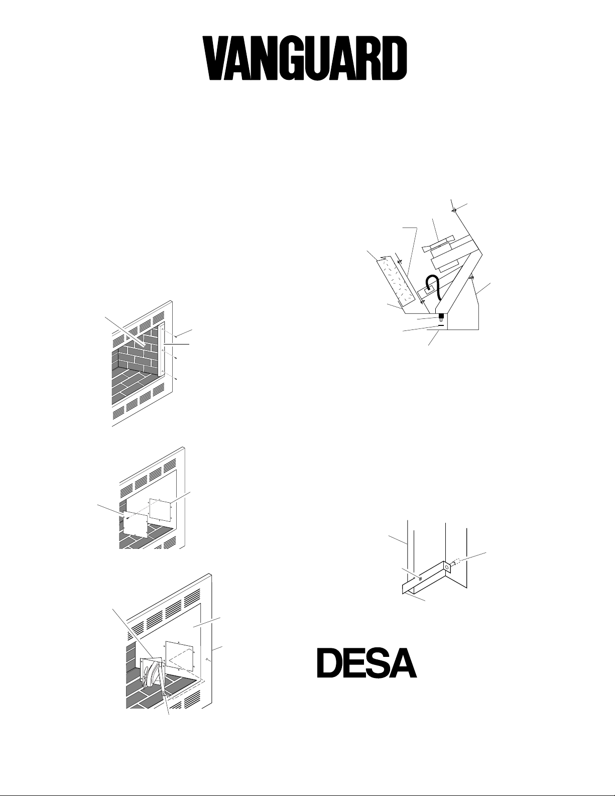
1. Remove the three screws that secure side brick retainers. Pull
out the side brick exposing blower cover plate on the right side
of fireplace (see Figure 6).
2. Remove the blower cover plate (see Figure 7).
3. Take the blower assembly and place through hole in the fire-
box. Make sure ON/OFF switch protrudes through the hole in
the fireplace side (see Figure 8). Blower assembly should now
look similar to Figure 9.
Figure 9 - Connecting Blower Assembly Power Supply and ON/
OFF Switch (Top View)
Screw
ON/OFF Switch
Knurled Nut
Fireplace Face
Blower
Assembly
Fireplace
Firebrick
Firebrick
Retainer
Blower
Cover Plate
Figure 6 - Removing Side Brick
Figure 7 - Removing Fan Cover Plate
Figure 8 - Installing Blower Assembly
Figure 10 - Attaching ON/OFF Switch to Fireplace with Glass
Doors
Side Brick
Side Brick
Retainer
Screw
Fan Cover
Plate
Knockout
Plate
Firebox
Blower
Assembly
Fireplace
Side
ON/OFF Switch
Right Door
Frame
Pop Rivet
Switch Arm
ON/OFF
Switch
INTERNATIONAL
2701 Industrial Drive
P.O. Box 90004
Bowling Green, KY 42102-9004
www.desatech.com
55613
Rev. A
06/99
®
VCBK4R AND VCBK4L BLOWER
4. Secure ON/OFF switch with knurled nut in kit. Before replac-
ing blower cover plate, plug male electrical connector on the
blower assembly into the female socket already in the fireplace.
5. Replace blower cover plate, side brick, and retainer before
using fireplace.

This manual suits for next models

1

Popular Blower manuals by other brands

Elektror S-MP 345/20 Operation and assembly instructions

Elektror

Elektror S-MP 345/20 Operation and assembly instructions

Makita EB7660TH Original instruction manual

Makita

Makita EB7660TH Original instruction manual

Hearth & Home HHSTDF26I User's manual and operating instructions

Hearth & Home

Hearth & Home HHSTDF26I User's manual and operating instructions

Garland GAS 800 MG-V18 instruction manual

Garland

Garland GAS 800 MG-V18 instruction manual

Maruyama BL55 owner's manual

Maruyama

Maruyama BL55 owner's manual

Husqvarna 150BT Operator's manual

Husqvarna

Husqvarna 150BT Operator's manual

Craftsman 316.7948 Operator's manual

Craftsman

Craftsman 316.7948 Operator's manual

Black & Decker GW350 user manual

Black & Decker

Black & Decker GW350 user manual

Simco Aerostat PC instructions

Simco

Simco Aerostat PC instructions

TOOLCRAFT 1619736 operating instructions

TOOLCRAFT

TOOLCRAFT 1619736 operating instructions

Briggs & Stratton Series 82200 to 82299 Illustrated parts list

Briggs & Stratton

Briggs & Stratton Series 82200 to 82299 Illustrated parts list

Neuros NX Series installation guide

Neuros

Neuros NX Series installation guide

Makita DUB362 instruction manual

Makita

Makita DUB362 instruction manual

Milwaukee M18 BBL Original instructions

Milwaukee

Milwaukee M18 BBL Original instructions

Craftsman Incredi-Pull 316.794011 Operator's manual

Craftsman

Craftsman Incredi-Pull 316.794011 Operator's manual

Waterway SANTANNA 750-1011-280 instructions

Waterway

Waterway SANTANNA 750-1011-280 instructions

Shop-Vac 3050051 Important notice

Shop-Vac

Shop-Vac 3050051 Important notice

Jonsered BV32 Spare parts manual

Jonsered

Jonsered BV32 Spare parts manual

manuals.online logo
manuals.online logoBrands
  • About & Mission
  • Contact us
  • Privacy Policy
  • Terms and Conditions

Copyright 2025 Manuals.Online. All Rights Reserved.