VAT PLUTO Series User manual

VOLTA AIR
TECHNOLOGY
(VAT)
OWNER’S MANUAL –PLUTO SERIES
You shall read and understand this manual, before you
operate or install the refrigerator unit
RU.12.100/70 –V0

Volta Air Technology Owner’s Manual
Van Refrigeration & Freezer Unit
2
CONFIDENTIAL
Contents
Introduction .................................................................................................................................... 4
Safety Instructions .......................................................................................................................... 5
Safety Symbols & Messages........................................................................................................ 5
Intended Use ............................................................................................................................... 5
Precautions.................................................................................................................................. 6
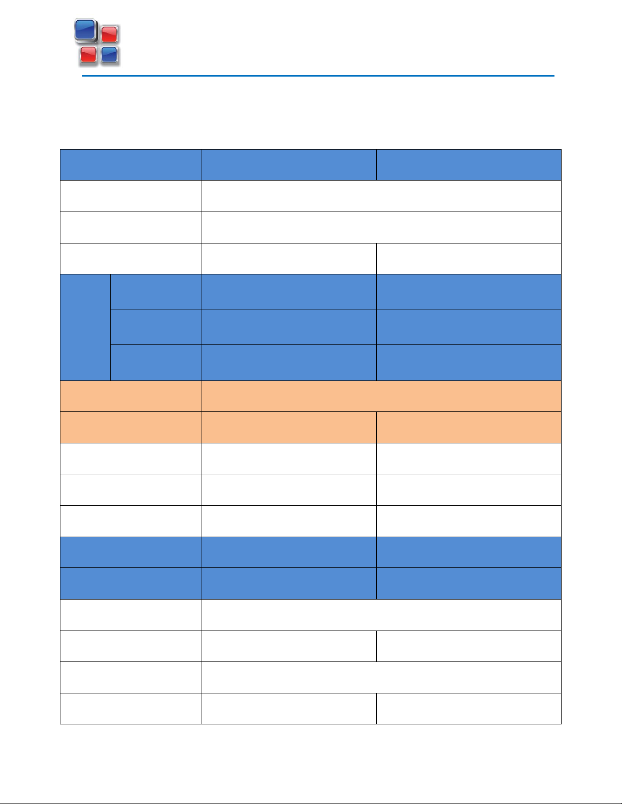
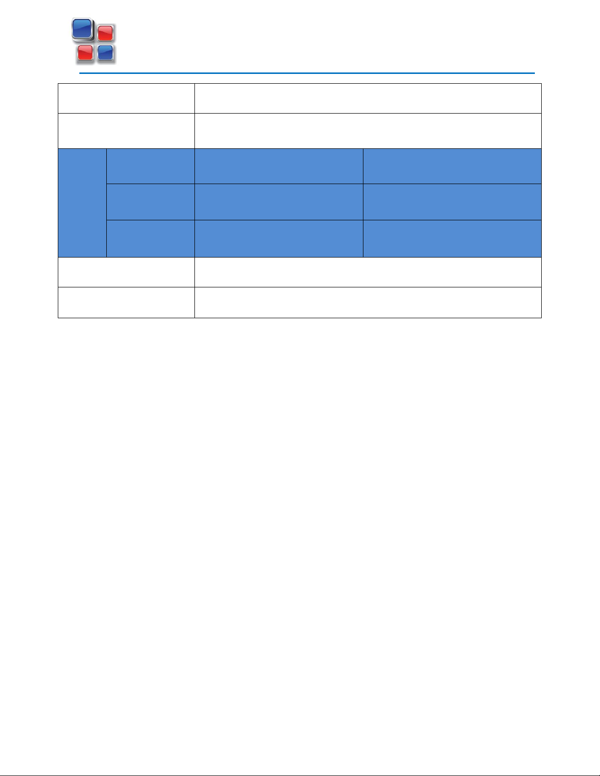
Technical Specifications.................................................................................................................. 7
System Description ....................................................................................................................... 11
Introduction............................................................................................................................... 11
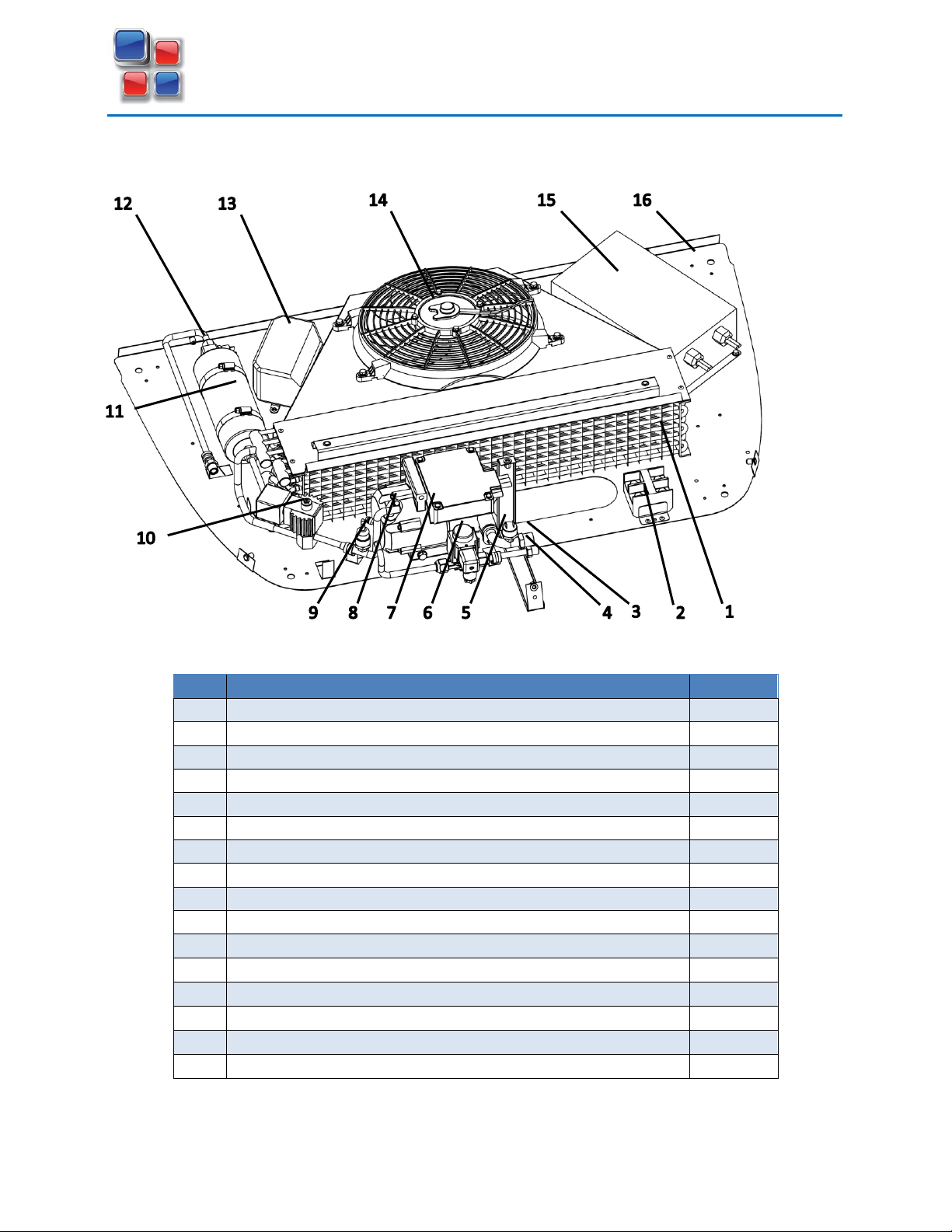
Condenser unit.......................................................................................................................... 11
Evaporator unit ......................................................................................................................... 13
Controller .................................................................................................................................. 14
Controller Parameter Setting ................................................................................................ 15
Unit conversion...................................................................................................................... 15
Defrost operation .................................................................................................................. 16
Heating mode ........................................................................................................................ 16
Controller/System Faults....................................................................................................... 16
Refrigeration cycles....................................................................................................................... 18
Cooling Cycle ............................................................................................................................. 18
Null mode .............................................................................................................................. 18
Defrost / Heating cycle.............................................................................................................. 18
Installation .................................................................................................................................... 20
Installation Conditions: ............................................................................................................. 20
Required Tools/Equipment ....................................................................................................... 21
Pluto mounting dimensions ...................................................................................................... 22
Pluto condenser / evaporator dimensions ............................................................................... 23
Pluto controller dimensions...................................................................................................... 24
Condenser Installation .............................................................................................................. 25

Volta Air Technology Owner’s Manual
Van Refrigeration & Freezer Unit
3
CONFIDENTIAL
Evaporator Installation.............................................................................................................. 28
Refrigerant Hose Installation .................................................................................................... 29
Power Cables Installation.......................................................................................................... 33
Drain Installation....................................................................................................................... 35
Controller Installation ............................................................................................................... 36
Energy Pack Connection............................................................................................................ 37
Testing for Leaks and Evacuation.............................................................................................. 38
Leak Testing ........................................................................................................................... 38
Evacuate System.................................................................................................................... 38
Charging the System.............................................................................................................. 38
Testing and Starting the System ............................................................................................... 40
Pluto Reefer Installation Checking List (ICL) ............................................................................. 41
Maintenance................................................................................................................................. 43
Condenser.............................................................................................................................. 43
Evaporator ............................................................................................................................. 43
Battery / Power ..................................................................................................................... 44
Electrical schematic wiring diagram ............................................................................................. 45
Troubleshooting............................................................................................................................ 46
Warranties and Contact Information............................................................................................ 51

Volta Air Technology Owner’s Manual
Van Refrigeration & Freezer Unit
4
CONFIDENTIAL
Introduction
Volta Air Technology provides this document for informational purposes only. Volta Air
Technology has devoted industrious efforts to compile a manual to assist customers with
operation and product usage, however Volta Air Technology makes no representations
warranties express or implied with respect to the information, recommendations and
descriptions contained within this document. Information from this manual should at no time be
regarded as covering all contingencies. If you are in need of additional information, contact Volta
Air Technology directly.
Volta Air Technology’s warranty shall not apply to any product which has been installed,
maintained, repaired or altered as, in the manufacturer’s judgment, to affect the product’s
integrity. Any alteration of these products and deviation from suggested installation process
without written approval will void Volta Air Technology’s warranty
Volta Air Technology accepts no liability to any person or entity for personal injury of any kind,
property damage, or any other direct, indirect, special, or consequential damages whatsoever
arising out of the use of this manual or deriving from any information, recommendations or
descriptions contained in this document.
To ensure the durability of Volta Air Technology products, please follow and understand the
instructions within this manual
Recycle and dispose of the refrigeration / freezer unit properly to help keep the environment
healthy
There are federal and state regulations regarding the disposal of refrigeration machines. Consult
a professional and ensure they follow the laws when disposing of the refrigeration unit
WARNIN
G!
1
Do not disassemble the unit yourself
Only qualified, specially trained personnel are allowed to dispose the unit

Volta Air Technology Owner’s Manual
Van Refrigeration & Freezer Unit
5
CONFIDENTIAL
Safety Instructions
Safety Symbols & Messages
Intended Use
These refrigeration and freezer units were designed for cooling reefer vans. Any other use is not
permitted unless permitted by Volta Air Technology
The LI models include a lithium battery to make for easy shore power integration. Essentially
eliminating the need to add an auxiliary battery
WARNING!
1
This symbol and alert message indicates a hazardous situation which, if not avoided,
could result in death or serious injuries
CAUTION!
1
This symbol and alert message indicates a hazardous situation which, if not avoided
could result in minor or moderate injuries or death
DANGER!
1
This symbol and alert message indicates an imminent hazard and failure to avoid
hazard will result in death
NOTICE
This symbol and message refers to information considered important, but not
hazard-related (e.g. property damage)

Volta Air Technology Owner’s Manual
Van Refrigeration & Freezer Unit
6
CONFIDENTIAL
The products were not designed to withstand explosions or fires. There is a risk of refrigerant
leaking from the products that may cause property damage, personal injury and in uncommon
cases death.
Precautions
NOTICE
The systems need some regular maintenance or checks, please refer to
Maintenance Schedule section
NOTICE
Please use products in described “normal” environments according to this manual
CAUTION!
1
Do not use these units for other purposes than cooling reefer vans.
WARNING!
1
Never install the unit while connected to electricity or power the unit using a loose
socket or damaged cord. Never plug or unplug the unit from the supply while your
hands are wet
WARNING!
1
Always use the proper PPE. Wear goggles, gloves, and safety shoes
WARNING!
1
Never drill holes into or heat up the refrigeration unit

Volta Air Technology Owner’s Manual
Van Refrigeration & Freezer Unit
7
CONFIDENTIAL
Technical Specifications
Model
Pluto
Pluto +
Voltage
12V
Refrigerant
R134a
Refrigerant weight
1.3 kg (2.8 lbs)
1.9 kg (4.2 lbs)
Cooling capacity
+5℃(41℉)
2100 W (7200 BTU/H)
3200 W (11000 BTU/H)
0℃(32℉)
1700 W (5800 BTU/H)
2600 W (8900 BTU/H)
-15℃(5℉)
700 W (2400 BTU/H)
1100 W (3800 BTU/H)
Heating option
Hot gas heating
Heating capacity
1000 W (3400 BTU/H)
1500 W (5100 BTU/H)
Compressor type
12V DC Brushless Electrical
24V DC Brushless Electrical
Evaporator fan speed
≧950m³/h (560 CFM)
≧1380 m³/h (810 CFM)
Condenser fan speed
≧750m³/h (440 CFM)
≧980m³/h (580 CFM)
Working current
12V 85A
12V 128A
Max current
12V 110A
12V 168A
Condenser dimensions
1100 x 800 x 217 mm (43.3 x 32.8 x 8.5 in)
Condenser weight
30 kg (66 lbs)
35 kg (77 lbs)
Evaporator dimension
766 x 530 x 153 mm (30.2 x 20.9 x 6 in)
Evaporator weight
13.5 kg (29.7 lbs)
16 kg (35.2 lbs)

Volta Air Technology Owner’s Manual
Van Refrigeration & Freezer Unit
8
CONFIDENTIAL
Deforester
Hot gas defrost
Control panel
Digital (Celsius –Fahrenheit)
Applicable Volume
+5℃(41℉)
10-12 m³ (353-424 ft³)
13-15 m³ (424-494 ft³)
0℃(32℉)
8-10 m³ (282-353 ft³)
11-13 m³ (353-424 ft³)
-15℃(5℉)
6-8 m³ (212-282 ft³)
9-11 m³ (282-353 ft³)
Package Size (Condenser)
1100 x 850 x 300mm (43.3 x 33.5 x 11.8in)
Package Size (Evaporator)
800 x 560 x 170mm (31.5 x 22.0 x 6.7in)

Volta Air Technology Owner’s Manual
Van Refrigeration & Freezer Unit
11
CONFIDENTIAL
System Description
Introduction
Pluto refrigeration unit is intended for usage in insulated vans or trailers to achieve temperatures
from -12°C to 5°C (10°F to 41°F). The unit is of a split system with the outside condenser unit and
inside evaporator unit. The system is DC 12V fully electric and can be powered either from the
engine alternator, auxiliary battery box, or shore-power plug-in converter.
Condenser unit
The condenser unit is a roof-mount system that can be nose-mounted using extra L-brackets.

Volta Air Technology Owner’s Manual
Van Refrigeration & Freezer Unit
12
CONFIDENTIAL
Condenser unit contains the condenser coil, condenser fan, receiver-drier, compressor, energy
stabilizer module, Relay-fuse box, safety pressure switches, and electrical terminal block.
Item
Description
Part ID
1
Condenser coil
RCC005
2
Electrical terminal block
TRB001
3
Compressor suction port –SAE 7/8
FIT017
4
Hot gas port –SAE 5/8
FIT016
5
Low pressure switch
LPS001
6
Hot gas solenoid valve (HGSV) –normally closed
SVL004
7
Compressor –DC 12V –90A
CMP001
8
Compressor discharge line
FIT014
9
High pressure switch
HPS002
10
Condenser pressure control valve (CPCV) –normally open
SVL002
11
Receiver –drier - filter
RDF001
12
Liquid line port –SAE 5/8
-
13
Relay-fuse box ASM
RLA006
14
Condenser fan –DC 12V –12A
FAN009
15
Energy stabilizer module
POW004
16
Condenser base plate
PLT002

Volta Air Technology Owner’s Manual
Van Refrigeration & Freezer Unit
13
CONFIDENTIAL
Evaporator unit
The evaporator unit is mounted inside the insulated compartment and circulates the cold air. It
is connected to the condenser unit with 3 refrigerant lines; suction, liquid, and hot gas. Also, it
needs to be connected to a water drain to allow the condensed water out of the cooled area.
The evaporator unit consists of; evaporator coil, TXV (thermostatic expansion valve), cooling fans,
air and defrost temperature sensors, and CPR (compressor pressure regulating) valve.
Item
Description
Part ID
1
Evaporator base plate
PLT007
2
Evaporator coil
REC002
3
Defrost temperature sensor
TSE002
4
Thermostatic Expansion Valve (TXV)
TXV002
5
Liquid line port –SAE 5/8
-
6
Hot gas port –SAE 5/8
-
7
Suction port –SAE 7/8
-
8
CPR valve
CPR001
9
Evaporator fan –DC 12V –5A
FAN008
10
Air temperature sensor
TSE001
11
Evaporator cover
COV007
12
Condensed water drain
-
13
Stainless steel bolt & washer - M6x25mm
BLA001

Volta Air Technology Owner’s Manual
Van Refrigeration & Freezer Unit
14
CONFIDENTIAL
Controller
The digital controller enables the operator to adjust the box temperature as well as monitoring
the system; voltage, cooling mode, operating hours, and possible fault codes. User can set up the
controller for automatic or manual defrost and also activate the heating mode if is required in
cold environment.
Power Button
Turns the power on when is pressed once, to turn the power off press and hold the power button
until display goes off and only the power button is illuminated.
Defrost Button
If the temperature is below the set defrost temperature, pressing the defrost button will start
the defrost function manually. To turn off the defrost function hold the defrost button for 3
seconds
Increase Button
While in normal controller display pressing the increase button will raise the set desired
temperature in the setting mode the increase button will cycle through parameter codes. When
changing parameter values this will increase the current set parameter

Volta Air Technology Owner’s Manual
Van Refrigeration & Freezer Unit
15
CONFIDENTIAL
Decrease Button
While in normal controller display pressing the decrease button will lower the set desired
temperature in the setting mode the decrease button will cycle through parameter codes. When
changing parameter values this will decrease the current set parameter
Setting Button
Pressing the setting button will display the current set desired temperature. To enter the setting
mode hold the setting button, this mode will allow you to change the controller’s parameters
Display Button
Pressing the display button will cycle through current system parameters; defrost (evaporator
core) temperature, outlet temperature, system voltage, and total running time.
Controller Parameter Setting
Hold the setting button and the controller will display F01 to F08, you can cycle
through the parameters by pressing the increase/decrease buttons. To change the desired
parameters value press the setting button again. After changing the value if no buttons are
pressed for five seconds or cycle button pressed the entered value is confirmed.
Function
Description
Default
Range
F01
Defrost limit temperature setting
+15℃
0℃—20℃
F02
Defrost termination temperature setting
+25℃
3℃—35℃
F03
Defrost operation time
7 mins
0—30 minutes
F04
Defrost operation interval
2 hours
1—10 hours
F05
Temperature calibration
0℃
-10.0℃—10.0℃
F06
Temperature differential
2℃
1℃—10℃
F07
Temperature unit (Celsius / Fahrenheit)
Celsius
NA
F08
Cooling / Heating mode
Cooling
NA
Unit conversion
You can switch between Celsius and Fahrenheit unit by changing the controller setting at function
FO7.

Volta Air Technology Owner’s Manual
Van Refrigeration & Freezer Unit
16
CONFIDENTIAL
Defrost operation
Defrost mode starts only if the defrost temperature sensor (evaporator core temperature) is
lower than the limit temperature set at F01. Defrost stops if the defrost temperature reaches the
termination temperature set at F02, the operation time is over, or the defrost button held for 3
seconds. There is 30 seconds delay to drain the water before going back to cooling mode.
Automatic defrost is set up on the controller by default and setting parameters can be changed
regarding the application on function F01 to F04.
Manual defrost is available by pressing the defrost button once in cooling mode. Defrost
operation can be stopped by holding the defrost button for 3 seconds.
Heating mode
Heating is applicable if box temperature is lower than the set point temperature. Heating cycle
is very similar to defrost cycle, but evaporator fans continue running to circulate the heated air
throughout the box.
To activate the heating option, controller setting has to be changed at function F08 and then
reset the controller by turning it off and on. User needs to switch between the cool and heat
mode manually and reset the controller after to activate them.
Controller/System Faults
Fault code
Description
System response
OPE 1
Air temperature sensor is
open circuit
If set temperature is below 0°C system will
continue, if it is above 0°C system will stop
SHr 1
Air temperature sensor is
short circuit
OPE 2
Defrost temperature
sensor is open circuit
The defrost termination temperature
function is disabled. The defrost function
does not affect the system operation
SHr 2
Defrost temperature
sensor is short circuit
OPE 3
Ambient temperature
sensor is open circuit
Does not affect the system operation

Volta Air Technology Owner’s Manual
Van Refrigeration & Freezer Unit
17
CONFIDENTIAL
SHr 3
Ambient temperature
sensor is short circuit
HPEr
System high pressure
alarm
System shuts down
LPEr
System low pressure alarm
HUEr
System high voltage > 16V
System shuts down
LUEr
System low voltage < 10V
System shuts down
Note: When a fault occurs, if there is only one fault code it is displayed alternating with the reefer
unit temperature. If the number of faults exceeds one it will display “Errx” (x is the number of
faults) and the fault codes will alternate being displayed.

Volta Air Technology Owner’s Manual
Van Refrigeration & Freezer Unit
18
CONFIDENTIAL
Refrigeration cycles
Cooling Cycle
In cooling mode system works as a vapor compression refrigeration cycle. Compressor pushes
the high pressure/temperature refrigerant through the condenser coil. Superheated refrigerant
passes some heat to ambient air through the condenser heat exchanger coil and turn to liquid.
Subcooled liquid gets clean and dry in receiver-drier and goes to TXV (thermostatic expansion
valve). The externally equalized TXV drops the refrigerant pressure and meters the flow rate
through the evaporator coil based on the available heat load. Saturated refrigerant turns to vapor
passing through the evaporator coil by absorbing the heat from the air and comes back to
compressor suction inlet. Evaporator fans circulate the cooled air inside the refrigerated box to
cool down the products.
Null mode
Once the box temperature reaches the set point, the system enters the null mode to maintain
the desired temperature. It means the compressor and condenser fan stay off until the box
temperature raises certain amount of degrees higher than the set point temperature and then
system automatically switches to cooling mode.
Defrost / Heating cycle
Defrost is necessary to remove the frost and ice built up on the evaporator coil from the
condensed air moisture during the cooling cycle. Frost formation reduces the evaporator unit
performance significantly by blocking the air circulation passed between the evaporator fins thus
lowering the heat transfer rate. To melt and drain the frosted water, the control system bypasses
the condenser coil and TXV in refrigerant cycle and hot gas sent directly from compressor to
evaporator while evaporator fans are off. This happens by energizing couple of solenoid valves,
HGSV (hot gas solenoid valve) and CPCV (condenser pressure control valve) during defrost cycle.
The main difference between heating and defrost cycle is that the evaporator fan continue
running in heating mode to circulate the warmed air throughout the box. Control system may
switch to null mode during heating if box temperature reaches the set point.
CAUTION!
1
Control system does not switch automatically between the cooling and
heating mode. This should be done by the operator manually on the
controller.

Volta Air Technology Owner’s Manual
Van Refrigeration & Freezer Unit
19
CONFIDENTIAL
Cond. Pressure
control valve
Condenser
Evaporator
LPS
HPS
Hot gas
solenoid valve
Receiver-Drier
TXV
CPR Valve Comp.
Suction
charging port
Discharge
charging port
TXV equalizer line
CPCS
Cond. Pressure
control valve
Condenser
Evaporator
LPS
HPS
Hot gas
solenoid valve
Receiver-Drier
TXV
CPR Valve Comp.
Suction
charging port
Discharge
charging port
TXV equalizer line
CPCS

Volta Air Technology Owner’s Manual
Van Refrigeration & Freezer Unit
20
CONFIDENTIAL
Installation
Installation Conditions:
1. Read the Installation section to understand how the unit is mounted and installed before
starting
2. Mounting surfaces must be clean and free of debris
3. Confirm the unit is delivered in accordance to your order. View the checklist and compare
with the description on the order
4. Scan the unit for any damage, if you can see damage document and take photos of the
damage
5. Gather all needed equipment for installation listed or discussed with VAT representative
6. Verify that the van or trailer is designed or prepped for refrigeration / freezer applications.
Check the seals at the doors, floor, and corners of the space
7. Verify roof is reinforced to support both the roof mount condenser unit and inside roof
evaporator unit. Please look to technical specifications for weight and space requirements
8. Make sure there is no interference with any OEM electrical wiring, supports, etc. before
drilling or cutting into the vehicle
9. Discuss with customer or consider application, keeping important spaces open and
enough clearance at doors / roof for easy use of the system
10. Prepare additional mounting hardware since there are differences between vehicle types,
models, and applications
WARNING!
1
Ensure all equipment; especially safety gear is in good condition
CAUTION!
1
Use caution when working on vehicle, damage could occur when adding weight. If
necessary roof and walls should be reinforced

Volta Air Technology Owner’s Manual
Van Refrigeration & Freezer Unit
21
CONFIDENTIAL
Required Tools/Equipment
•Tape measure
•Utility knife
•Drill/Impact gun
•Hole-saw kit
•Drill bit set
•Caulking gun
•Angle grinder
•Hacksaw
•Rivet gun
•Wrench set
•Crimping tool
•Pliers
•Wire cutters
•Wire crimpers
•Torch
•134A recovery/recharge machine
•Zap straps / Zip ties
•Silicone
•¼” rivets
•4 gauge battery wire (+/-) 20-25’long
•4 gauge 3/8” hole terminal ends
•½” double wall shrink tubing
•Butt connectors (14-22 AWG)
•Expanding foam
•Wire loom, plastic wire cover
•C-clamp 2” for wire and hoses
•¼” x ¾” nut and bolt

Volta Air Technology Owner’s Manual
Van Refrigeration & Freezer Unit
22
CONFIDENTIAL
Pluto mounting dimensions
This manual suits for next models
1
Table of contents
Other VAT Refrigerator manuals