VAT 615 DN Series Assembly instructions

Installation, Operating & Maintenance Instructions
Series 615 DN 40 (I.D. 1.5”), RS485
VAT Vakuumventile AG, CH-9469 Haag, Switzerland
289111EB
2013-02-05
1/96
Butterfly control & isolation valve
with extended control range
with RS485 interface
sample picture
This manual is valid for the valve ordering number(s):
61532-KEGJ-0002
configured with firmware 615P.1E.31
The fabrication number is indicated on each product as per the label
below (or similar):
made in Switzerland
Fabrication No.:
615 .. –.... –.... /....
A–.. ....
Fabrication number
Explanation of symbols:
Read declaration carefully before you start any other
action!
Keep body parts and objects away from the valve
opening!
Attention!
Hot surfaces; do not touch!
Loaded springs and/or air cushions are potential
hazards!
Wear gloves!
Disconnect electrical power and compressed air
lines. Do not touch parts under voltage!
Read these «Installation, Operating & Maintenance Instructions» and the enclosed «General
Safety Instructions» carefully before you start any other action!

Installation, Operating & Maintenance Instructions
Series 615 DN 40 (I.D. 1.5”), RS485
VAT Vakuumventile AG, CH-9469 Haag, Switzerland
289111EB
2013-02-05
2/96
Imprint
Manufacturer
VAT Vakuumventile AG, CH-9469 Haag, Switzerland
Website
www.vatvalve.com
Phone
+41 81 771 61 61
Fax
+41 81 771 48 30
Publisher
VAT Vakuumventile AG, CH-9469 Haag, Switzerland
Editor
VAT Vakuumventile AG, CH-9469 Haag, Switzerland
Print
VAT Vakuumventile AG, CH-9469 Haag, Switzerland
Copyright
© VAT Vakuumventile AG 2011
No part of these Instructions may be reproduced in any way (photocopies, microfilms or any
other reproduction processes) nor may it be manipulated with electronic systems, duplicated or
distributed without written permission from VAT. Offenders are liable to pay damages.
The original VAT firmware and updated state of the art versions of the VAT firmware are
intended for use with VAT products. The VAT firmware contains a limited, time unlimited user
license. The VAT firmware may not be used for purposes other than those intended nor is it
permitted to make copies of the VAT firmware. In particular, it is strictly forbidden to give
copies of the VAT firmware to other people.
The use of trade names, brand names, trademarks, etc. in these Instructions does not entitle
third parties to consider these names to be unprotected and to use them freely. This is in
accordance with the meaning of the laws and acts covering brand names and trademarks.

Installation, Operating & Maintenance Instructions
Series 615 DN 40 (I.D. 1.5”), RS485
VAT Vakuumventile AG, CH-9469 Haag, Switzerland
289111EB
2013-02-05
3/96
Contents:
1Use of product .......................................................................................................................................................... 5
1.1 Technical data.................................................................................................................................................. 6
2Installation................................................................................................................................................................. 8
2.1 Unpacking........................................................................................................................................................ 8
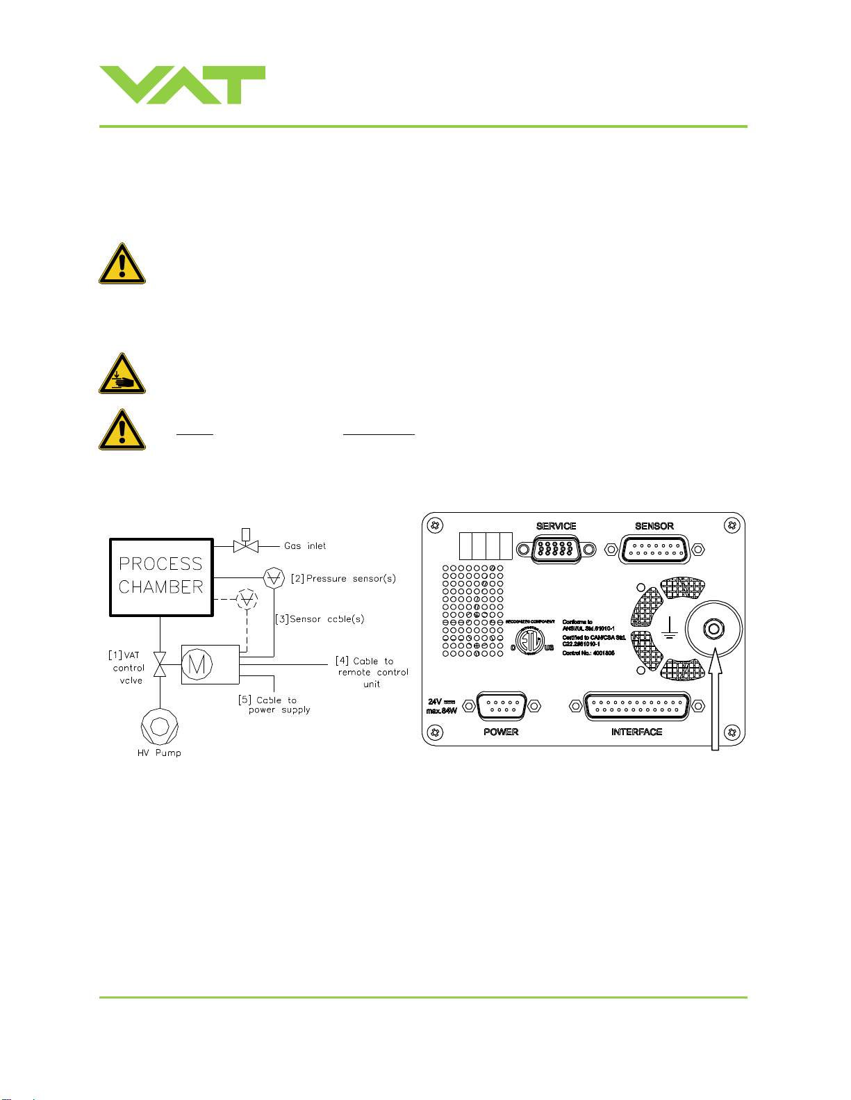
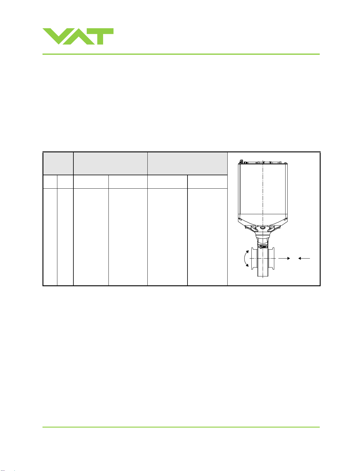
2.2 Installation into the system .............................................................................................................................. 8
2.3 Tightening torque........................................................................................................................................... 10
2.3.1 Mounting of ISO-KF flanges .............................................................................................................. 10
2.4 Admissible forces........................................................................................................................................... 10
2.4.1 Admissible forces at controller .......................................................................................................... 11
2.5 Requirements to sensor connection .............................................................................................................. 12
2.6 Electrical connection...................................................................................................................................... 13
2.6.1 Ground connection............................................................................................................................ 13
2.6.2 Sensor supply concepts .................................................................................................................... 14
2.6.3 Power and sensor connection (+24 VDC sensors)............................................................................ 15
2.6.4 Power and sensor connection ( 15 VDC sensors) without optional SPS module............................. 17
2.6.5 RS485 interface connection .............................................................................................................. 19
2.6.6 Service port connection..................................................................................................................... 19
3Operation................................................................................................................................................................ 20
3.1 Introduction.................................................................................................................................................... 20
3.1.1 Local operation.................................................................................................................................. 21
3.1.2 Remote operation.............................................................................................................................. 21
3.1.3 Safety mode ...................................................................................................................................... 22
3.2 Operation under increased temperature........................................................................................................ 22
3.3 Behavior during power up.............................................................................................................................. 22
3.4 Behavior in case of power failure................................................................................................................... 22
3.5 Display information ........................................................................................................................................ 23
3.6 Setup procedure ............................................................................................................................................ 25
3.6.1 Interface configuration....................................................................................................................... 25
3.6.2 LOGIC I/O configuration.................................................................................................................... 27
3.6.3 Valve and sensor configuration......................................................................................................... 28
3.6.4 ZERO................................................................................................................................................. 28
3.6.5 Pressure control configuration........................................................................................................... 29
3.6.6 Control algorithms ............................................................................................................................. 31
3.7 Close valve .................................................................................................................................................... 35
3.8 Open valve..................................................................................................................................................... 35
3.9 Position control .............................................................................................................................................. 36
3.10 Pressure control............................................................................................................................................. 36
3.11 Tuning of pressure control performance........................................................................................................ 36
3.11.1 Tuning of pressure control (adaptive)................................................................................................ 37
3.11.2 Tuning of pressure control performance with fixed PI control............................................................ 42
3.11.3 Tuning of pressure control (soft pump).............................................................................................. 47
3.12 RS485 interface............................................................................................................................................. 50
3.12.1 Settings.............................................................................................................................................. 50
3.12.2 Schematics........................................................................................................................................ 50
3.12.3 RS485 network topology ................................................................................................................... 53
3.12.4 Connection cable drawing................................................................................................................. 53
3.12.5 Digital inputs...................................................................................................................................... 54
3.12.6 Command syntax............................................................................................................................... 55
3.12.7 Addressed communication................................................................................................................ 55
3.12.8 RS485 Control commands ................................................................................................................ 56
3.12.9 RS485 Inquiry commands................................................................................................................. 57
3.12.10RS485 Setup commands................................................................................................................... 62
3.12.11Error messages................................................................................................................................. 69
4Trouble shooting..................................................................................................................................................... 70
5Maintenance & repairs............................................................................................................................................ 73
5.1 Maintenance procedures ............................................................................................................................... 73

Installation, Operating & Maintenance Instructions
Series 615 DN 40 (I.D. 1.5”), RS485
VAT Vakuumventile AG, CH-9469 Haag, Switzerland
289111EB
2013-02-05
4/96
5.1.1 Replacement of plate o-ring .............................................................................................................. 75
5.1.2 Replacement of shaft feedtrough seals and plate o-ring................................................................... 78
5.2 Option board.................................................................................................................................................. 87
5.2.1 Durability of power fail battery ........................................................................................................... 87
5.2.2 Retrofit / replacement procedure....................................................................................................... 88
6Drawing................................................................................................................................................................... 91
7Spare parts ............................................................................................................................................................. 92
7.1 Control and actuating unit.............................................................................................................................. 92
7.2 Valve unit....................................................................................................................................................... 93
7.3 Seal kit........................................................................................................................................................... 93
7.4 Accessories ................................................................................................................................................... 94
7.4.1 Centering ring with Viton o-ring......................................................................................................... 94
8Warranty................................................................................................................................................................. 95

Installation, Operating & Maintenance Instructions
Series 615 DN 40 (I.D. 1.5”), RS485
VAT Vakuumventile AG, CH-9469 Haag, Switzerland
289111EB
2013-02-05
5/96
1 Use of product
This product is a Butterfly control valve with isolation functionality for downstream pressure control in vacuum systems.
Use product for clean and dry indoor vacuum applications under the conditions indicated in chapter «Technical data» only!
Other applications are only allowed with the written permission of VAT.

Installation, Operating & Maintenance Instructions
Series 615 DN 40 (I.D. 1.5”), RS485
VAT Vakuumventile AG, CH-9469 Haag, Switzerland
289111EB
2013-02-05
6/96
1.1 Technical data
Control and actuating unit
Input voltage 1)
+24 VDC (±10%) @ 0.5 V pk-pk max.
[connector: POWER]
Power consumption
38 W
[connector: POWER]
Sensor power supply output 2)
+24 VDC / 1500 mA max.
[connector: SENSOR]
Sensor input
Signal input voltage / Input resistance
ADC resolution
Sampling time
0-10 VDC / Ri>100 kΩ (linear to pressure)
0.23 mV
10 ms
[connector: SENSOR]
Digital inputs 3)
±24 VDC max.
[connector: INTERFACE]
Digital outputs 3)
Input voltage
Input current
Breaking capacity
70 VDC or 70 V peak max.
0.5 ADC or 0.5 A peak max.
10 W max.
[connector: INTERFACE]
Analog outputs 3) (optional)
0-10 VDC / 1 mA max.
[connector: INTERFACE]
PFO4) battery pack
Charging time
Durability
2 minutes max.
up to 10 years @ 25°C ambient
refer to «Durability of power fail battery» for details
Ambient temperature
0 °C to +50 °C max. (<35 °C recommended)
Pressure control accuracy
5 mV or 0.1% of setpoint, whichever is greater
Position resolution / position control capability
>28000 (full stroke)
Closing time throttling only
0.5 s (full stroke)
Opening time throttling only
0.5 s (full stroke)
Closing time throttling & isolation
0.6 s (full stroke)
Opening time throttling & isolation
0.6 s (full stroke)
1) Internal overcurrent protection by a PTC device.
2) Refer to chapter «Sensor supply concepts» for details.
3) Refer to chapter «Schematics» for details.
4) PFO = Power Failure Option. Refer to «Behavior in case of power failure» for details.

Installation, Operating & Maintenance Instructions
Series 615 DN 40 (I.D. 1.5”), RS485
VAT Vakuumventile AG, CH-9469 Haag, Switzerland
289111EB
2013-02-05
7/96
Valve unit
Pressure range at 20 C
1 x 10E-8 mbar to 1.2 bar (abs)
Leak rate to outside at 20 C
1 x 10E-9 mbar l/s
Leak rate valve seat at 20 C
1 x 10E-9 mbar l/s
Cycles until first service:
- Isolation cycles (open - closed - open)
250‟000 (with FKM (e.g. Viton®) seals, under clean and unheated conditions)
- Throttling cycles (open - max. throttle - open)
2‟000‟000 (with FKM (e.g. Viton®) seals, under clean and unheated
conditions)
Admissible operating temperature
10°C to +120°C
Mounting position
Valve seat must face chamber side. Control unit for ISO-KF version needs
support, when mounted on horizontal piping and control unit does not hang.
Wetted Materials
- Body
Stainless steel 316L (1.4404 or 1.4435)
- Plate
Stainless steel 316L (1.4404 or 1.4435)
- Shaft
Stainless steel 316L (1.4404 or 1.4435)
- Plate screws
Stainless steel 316L (A4)
- Plate seal
FKM (e.g. Viton®)
- Rotary feedthrough seals atmosphere side
FKM (e.g. Viton®)
- Rotary feedthrough seals vacuum side
FKM (e.g. Viton®)
- Slide bearing for shaft
iglidur® X
Other parts
Stainless steel 316L (1.4404 or 1.4435), 1.4122, 301 (1.4310), 304 (1.4303), 1.4571, 304 (A2)
Max. differential pressure on plate during isolation
1000 mbar
Max. differential pressure on plate
during opening and throttling
1000 mbar
Min. controllable conductance [N2molecular flow]
0.05 l/s
Conductance in open position [N2molecular flow]
60 l/s
Weight about
3.3 kg
Dimensions
Refer to dimensional drawing of specific valve ordering number
(available on request)

Installation, Operating & Maintenance Instructions
Series 615 DN 40 (I.D. 1.5”), RS485
VAT Vakuumventile AG, CH-9469 Haag, Switzerland
289111EB
2013-02-05
8/96
2 Installation
2.1 Unpacking
Valves DN63 / 2½" and larger must not be lifted solely by the actuator.
2.2 Installation into the system
Fingers and objects must be kept out of the valve opening and away from moving parts.
The valve plate may start to move just after power is supplied.
Do not connect or disconnect sensor cable when device is under power.
Connection overview Connectors at controller panel
Ground
connection

Installation, Operating & Maintenance Instructions
Series 615 DN 40 (I.D. 1.5”), RS485
VAT Vakuumventile AG, CH-9469 Haag, Switzerland
289111EB
2013-02-05
9/96
1. Install valve [1] into the vacuum system. Valve seat side must faced process chamber. The valve seat side is
indicated by the symbol " " on the valve flange.
Caution: Do not tighten the flange screws stronger than indicated under «Tightening torque».
Caution: Do not admit higher forces to the valve than indicated under «Admissible forces».
Note: Make sure that enough space is kept free to do preventive maintenance work. The required space is indicated
on the dimensional drawing.
Note: Control unit of valves with ISO-KF flanges (615 . . –K. . . ) needs support when mounted on horizontal piping
and control unit does not hang.
2. Install a ground connection cable at controller. Refer to «Electrical connection»
3. Install sensor(s) [2] according to the recommendations of the sensor manufacturer and directives given under
«Requirements to sensor connection».
4. Connect pressure sensor cable [3] to sensor(s) and then to valve (connector: SENSOR). Refer to chapter «Electrical
connection» for correct wiring.
Note: 61532-KEGJ-0002 supports 1 sensor(s).
5. Connect valve to remote control unit [4] (connector: INTERFACE). Refer to «RS485 connection» for correct wiring.
6. Connect power supply [5] to valve (connector: POWER). Refer to chapter «Electrical connection» for correct wiring.
Note: To provide power to the valve motor pins 4 and 8 must be bridged, otherwise motor interlock is active and the
valve enters the safety mode and is not operative. Refer also to «Safety mode».
7. This valve may optionally be equipped with a heating device. Connect VAT heating device according to manual of
respective heating device.
8. Perform «Setup procedure» to prepare valve for operation.
Note: Without performing the setup procedure the valve will not be able to do pressure control.

Installation, Operating & Maintenance Instructions
Series 615 DN 40 (I.D. 1.5”), RS485
VAT Vakuumventile AG, CH-9469 Haag, Switzerland
289111EB
2013-02-05
10/96
2.3 Tightening torque
2.3.1 Mounting of ISO-KF flanges
Tightening torques for ISO-KF flange connections depends on the type of seal which is used. Follow recommendations of
seal manufacturer.
2.4 Admissible forces
Forces from the weight of other components can lead to deformation of the valve body and to malfunction of the valve.
The stress has to be relieved by suitable means. The following forces are admissible:
Valve size
Axial tensile or
compressive force «FA»
Bending moment «M»
M FA
mm
inch
N
lb.
Nm
lbf.
40
1½
100
22
6
4.5

Installation, Operating & Maintenance Instructions
Series 615 DN 40 (I.D. 1.5”), RS485
VAT Vakuumventile AG, CH-9469 Haag, Switzerland
289111EB
2013-02-05
11/96
2.4.1 Admissible forces at controller
Attention!
Do not pushing, shocking load, or stressing the valve controller!
Do not deposit anything at valve controller!
The admissible force at valve controller in regards to the pedestal is shown in table below. In case higher force is
applied, the pedestal could be permanently damaged!
Admissible force «F»
Overview
F= Force
a = middle of aluminium part of controller (b / 2)
c = pedestal
400 N
a a
F
bc
a a
F
bc

Installation, Operating & Maintenance Instructions
Series 615 DN 40 (I.D. 1.5”), RS485
VAT Vakuumventile AG, CH-9469 Haag, Switzerland
289111EB
2013-02-05
12/96
2.5 Requirements to sensor connection
To achieve fast and accurate pressure control a fast
sensor response is required.
Sensor response time: < 50ms
The sensor is normally connected to the chamber by a
pipe. To maintain that the response time is not degraded
by this connection it needs to meet the following
requirements:
Inner diameter of connection pipe: > = 10 mm
Length of connection pipe: < = 300 mm
These conductance guidelines must include all valves
and limiting orifices that may also be present.
Make also sure that there is no obstruction in front of
sensor connection port inside the chamber.
The sensor should also be mounted free of mechanical
shock and vibration.
Dynamic stray magnetic fields may introduce noise to
sensor output and should be avoided or shielded.

Installation, Operating & Maintenance Instructions
Series 615 DN 40 (I.D. 1.5”), RS485
VAT Vakuumventile AG, CH-9469 Haag, Switzerland
289111EB
2013-02-05
13/96
2.6 Electrical connection
2.6.1 Ground connection
Recommendation for ground strap between controller and system (chassis)
Material
L (Length max.)
B1 (min.)
B2 (min.)
d1 ( )
d2 ( )
copper tinned
200 mm
25 mm
25 mm
4.5 mm
customized
Note: Connection plates of ground strap must be total plane for a good electrical contact!
Note: The connection point at chassis (FE) must be blank metal (not coated).
It is also possible to connect the ground strap at system chamber if it is well connected to PE.
Note: Avoid low chassis cross section to the system PE connection. (Min. same cross section as ground strap)
Valve controller
System
Ground connection
Chassis (FE)
(Functional Earth)
B1
B2
d1
d2
L
Ground strap
PE
Recommended torque: 1,3…1,7Nm

Installation, Operating & Maintenance Instructions
Series 615 DN 40 (I.D. 1.5”), RS485
VAT Vakuumventile AG, CH-9469 Haag, Switzerland
289111EB
2013-02-05
14/96
2.6.2 Sensor supply concepts
This valve offers 2 alternative concepts to supply the sensor(s) with power. This depends on the sensor type that is used.
Optional is this valve available with an sensor power supply module (SPS) that converts 15 VDC from the 24 VDC.
Concepts:
External + 24 VDC supplied to POWER connector is feed through to SENSOR connector to supply 24 VDC
sensors. Refer to chapter «Power and sensor connection (+24 VDC sensors)» for schematic and correct wiring.
External 15 VDC supplied to POWER connector is feed through to SENSOR connector to supply 15 VDC
sensors. Refer to chapter «Power and sensor connection ( 15 VDC sensors) without optional SPS module» for
schematic and correct wiring.
Valve versions:
615 . . - . . G. - . . . . and 615 . . - . . H. - . . . . SPS module not included
Note: The SPS module can be retrofitted. Refer to chapter «Retrofit / replacement procedure» for instruction.

Installation, Operating & Maintenance Instructions
Series 615 DN 40 (I.D. 1.5”), RS485
VAT Vakuumventile AG, CH-9469 Haag, Switzerland
289111EB
2013-02-05
15/96
2.6.3 Power and sensor connection (+24 VDC sensors)
[615 . . - . . G. - . . . . / 615 . . - . . H. - . . . . versions recommended]
2.6.3.1 Sensor power wiring via controller
Note:
Use shielded sensor cable(s). Keep cable as short as possible, but locate it away from noise sources.
Connect the +24 VDC sensors at DB–15 female sensor connector exactly as shown in the drawing above. Do not
connect other pins that may damage sensor, power supply or controller!
Connector: Use only screws with 4-40UNC thread for fastening the connectors!
Pins 4 and 8 must be bridged for operation!
An optional switch would allow for motor
interlock to prevent valve from moving.

Installation, Operating & Maintenance Instructions
Series 615 DN 40 (I.D. 1.5”), RS485
VAT Vakuumventile AG, CH-9469 Haag, Switzerland
289111EB
2013-02-05
16/96
2.6.3.2 Sensor power wiring external
Note:
Use shielded sensor cable(s). Keep cable as short as possible, but locate it away from noise sources.
Connect the +24 VDC sensors at DB–15 female sensor connector exactly as shown in the drawing above. Do not
connect other pins that may damage sensor, power supply or controller!
Connector: Use only screws with 4-40UNC thread for fastening the connectors!
Pins 4 and 8 must be bridged for operation!
An optional switch would allow for motor
interlock to prevent valve from moving.

Installation, Operating & Maintenance Instructions
Series 615 DN 40 (I.D. 1.5”), RS485
VAT Vakuumventile AG, CH-9469 Haag, Switzerland
289111EB
2013-02-05
17/96
2.6.4 Power and sensor connection ( 15 VDC sensors) without optional SPS module
[615 . . - . . G. - . . . . / 615 . . - . . H. - . . . . versions only]
2.6.4.1 Sensor power wiring via controller
Note:
Use shielded sensor cable(s). Keep cable as short as possible, but locate it away from noise sources.
Connect the 15 VDC sensors at DB–15 female sensor connector exactly as shown in the drawing above. Do not
connect other pins that may damage sensor, power supply or controller!
Connector: Use only screws with 4-40UNC thread for fastening the connectors!
Pins 4 and 8 must be bridged for operation!
An optional switch would allow for motor
interlock to prevent valve from moving.
Fuse 1A
Fuse 1A

Installation, Operating & Maintenance Instructions
Series 615 DN 40 (I.D. 1.5”), RS485
VAT Vakuumventile AG, CH-9469 Haag, Switzerland
289111EB
2013-02-05
18/96
2.6.4.2 Sensor power wiring external
Note:
Use shielded sensor cable(s). Keep cable as short as possible, but locate it away from noise sources.
Connect the 15 VDC sensors at DB–15 female sensor connector exactly as shown in the drawing above. Do not
connect other pins that may damage sensor, power supply or controller!
Connector: Use only screws with 4-40UNC thread for fastening the connectors!
Pins 4 and 8 must be bridged for operation!
An optional switch would allow for motor
interlock to prevent valve from moving.

Installation, Operating & Maintenance Instructions
Series 615 DN 40 (I.D. 1.5”), RS485
VAT Vakuumventile AG, CH-9469 Haag, Switzerland
289111EB
2013-02-05
19/96
2.6.5 RS485 interface connection
Refer to «Schematics» for wiring information.
2.6.6 Service port connection
The service port (connector: SERVICE) allows to connect the valve to a RS232 port of a computer.
This requires a service cable and software from VAT. You can either use our freeware 'Control View', which can be
downloaded from www.vatvalve.com or purchase our 'Control Performance Analyzer'.
Alternatively the VAT Service Box 2 can be connected to the service port for setup and local operation.
The service port is not galvanic isolated. Therefore we recommend using this only for setup, testing and maintenance and
not for permanent control.
Refer also to «Local Operation» for details and to «Spare parts / Accessories» for ordering numbers of service cable,
software and Service Box 2.
Connector: Use only screws with 4-40UNC thread for fastening the service port connector!

Installation, Operating & Maintenance Instructions
Series 615 DN 40 (I.D. 1.5”), RS485
VAT Vakuumventile AG, CH-9469 Haag, Switzerland
289111EB
2013-02-05
20/96
3 Operation
Valve opening
Fingers and objects must be kept out of the valve opening and away from moving
parts. Risk of injury.
Do not connect the controller to power before the valve isn‟t installed complete into the
system.
3.1 Introduction
This valve is designed for downstream pressure control in vacuum chambers. It can be employed in a pressure control
mode or a position control mode.
In both cases local or remote operation is possible.
Table of contents
Other VAT Refrigerator manuals