7
DETECTING WOOD & CALIBRATION
NOTE: The default detection mode of the sensor at startup is “Metal” indicated by I beam icon ( ) on LCD
display. Calibrate the sensor before use.
1. Press the On/Off (red) button to turn on the sensor. The green LED indicator turns on and followed by a short
beeping sound from the internal buzzer.
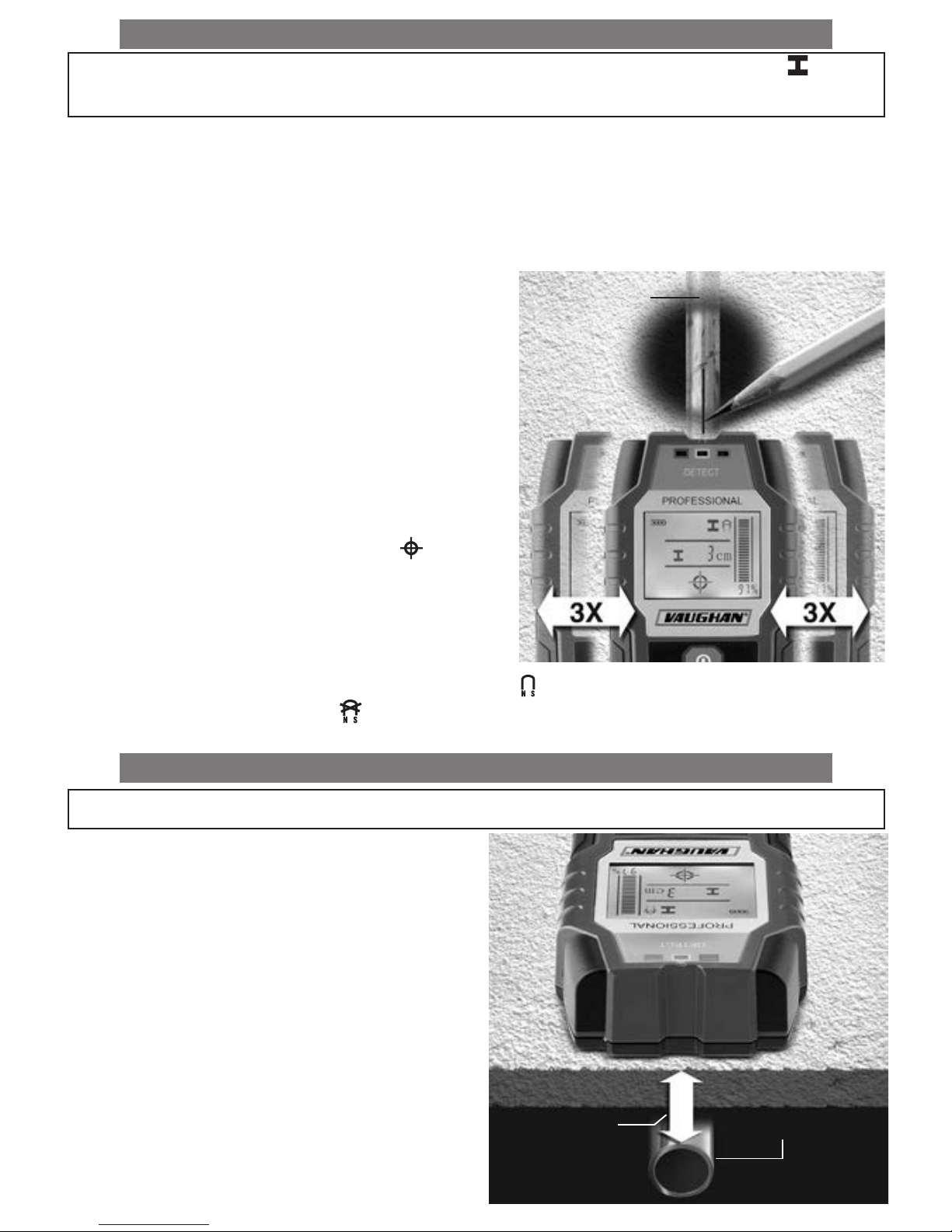
2. To calibrate, hold the bottom of the sensor close to the
surface to be scanned. DO NOT touch the bottom of
the sensor during calibration.
3. Press and hold the Wood (left black) button for a second
until the green LED turns off and then turns back on and
followed by a beeping sound. Wood icon ( ) will
appear in LCD display.
4. Calibration has been completed. Release the button.
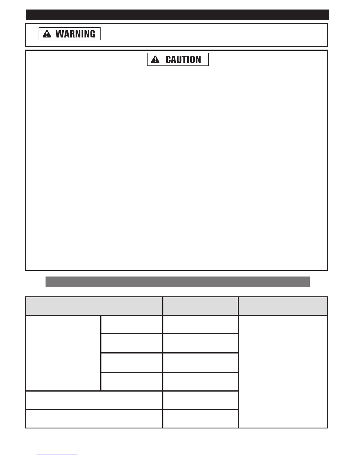
5. Place the sensor onto the surface to be scanned and
move the sensor side to side. As the sensor approaches/
moves away from the wooden object under the surface, the
signal detection strength bar and % value indicators on
LCD display increase/decrease. To locate the object more
precisely, slowly move the sensor three times (3x) side to
side over the object. When object is located directly below
the center of the sensor, indications will be at their max readings accompanied by cross-hair icon ( ), constant
beeping sound of the internal buzzer and illumination of red LED indicator. Mark the location with a pencil.
NOTE: When sensor detects an imperfection or defect in the wood such as burl, cracks, voids and inclusions, buzzer
beeps repeatedly including blinking red or yellow LED indicator. If such condition occurs, relocate the sensor to other
areas of the surface and resume scanning.
DETECTING LIVE WIRES & CALIBRATION
NOTE: The default detection mode of the sensor at the startup is “Metal” indicated by I beam icon ( ) on
LCD display. Calibrate the sensor before use.
1. Press the On/Off (red) button to turn on the sensor. The green LED indicator turns on and followed by a short
beeping sound from the internal buzzer.
2. To calibrate, hold the sensor in the air and away from metal objects (including personal jewelry such as wrist
watches or rings) or strong electric or magnetic field. DO NOT touch the bottom of the sensor during
calibration.
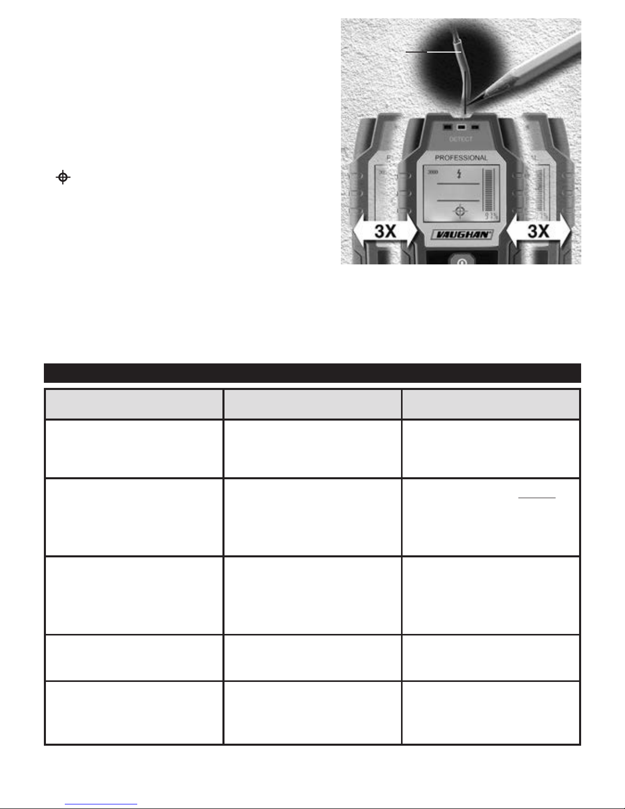
3. Press the metal/live wire (right black) button to select live wire detection. High Voltage icon ( ) will appear in
LCD display.
4. Press and hold the metal/live wire (right black) button for a few seconds until a beeping sound is heard. Green
LED remains turned on during the calibration.
5. Calibration has been completed. Release the button.
Wooden
Object
Surface