Sevcon Gen4 User manual

Gen4
Applications
Reference
Manual
Document no:
177/52701
Rev. 3.3

Sevcon Ltd
Kingsway South
Gateshead. NE11 0QA
England
Tel +44 (0)191 497 9000
Fax +44 (0)191 482 4223
Sevcon, Inc.
155 Northboro Road
Southborough, MA 01772
USA
Tel +1 (508) 281 5500
Fax +1 (508) 281 5341
Sevcon SAS
Parc d’Activité du Vert Galant
Rue Saint Simon
St Ouen l’Aumône
95041 Cergy Pontoise Cedex
France
Tel +33 (0)1 34 30 35 00
Fax +33 (0)1 34 21 77 02
Sevcon Japan K.K.
Kansai Office 51-26 Ohyabu
Hikone
Shiga Japan 522-0053
Tel +81 (0) 7 49465766
Sevcon Asia Ltd
Room No.202
Dong-Ah Heights Bldg
449-1 Sang-Dong Wonmi-Gu
Bucheon City Gyeounggi-Do
420-816 Korea
Tel +82 32 215 5070
Sevcon Germany
Hintere Str.32
73266 Bissingen an der Teck
Germany
Tel: +49 (0)170 9980294
www.sevcon.com

Table of Contents
Chapter 1: Introduction 1-1
About Gen4 documentation.......................................................1-2
This version of the manual.................................................................................................1-2
Copyright............................................................................................................................1-2
Scope of this manual.........................................................................................................1-2
Related documents............................................................................................................1-2
Drawings and units ............................................................................................................1-2
Dangers, Warnings, Cautions and Notes ..........................................................................1-3
Product identification label.........................................................1-4
Technical support......................................................................1-4
Product warranty .......................................................................1-4
Chapter 2: About the Gen4 2-1
Introduction................................................................................2-2
Standard features and capabilities.............................................2-2
Available options................................................................................................................2-2
Intended use of the Gen4..................................................................................................2-3
Available accessories ........................................................................................................2-3
Overview of a truck drive system...............................................2-4
Principles of operation...............................................................2-5
Functional description........................................................................................................2-5
Interfaces...........................................................................................................................2-6
Master-slave operation ......................................................................................................2-6
Torque mode .....................................................................................................................2-7
Speed mode ......................................................................................................................2-7
Safety and protective functions..................................................2-8
General..............................................................................................................................2-8
On-Highway Vehicles ......................................................................................................2-10
Fault detection and handling............................................................................................2-12

Doc. # 177/52701
Rev3
ii
Chapter 3: Installation 3-1
Mounting Gen4..........................................................................3-2
Location .............................................................................................................................3-2
Protection from chemical contamination............................................................................3-2
Orientation .........................................................................................................................3-2
Clearance for LED access.................................................................................................3-2
Mounting hole pattern........................................................................................................3-3
Equipment required: ..........................................................................................................3-3
Thermal grease application ...............................................................................................3-3
Cooling requirements ................................................................3-5
EMC guidelines .........................................................................3-6
General measures .............................................................................................................3-6
Measures required for specific signals ..............................................................................3-7
Additional measures ..........................................................................................................3-7
Problems to avoid..............................................................................................................3-8
Connecting power cables ..........................................................3-9
Battery and motor connections..........................................................................................3-9
Cable sizes ......................................................................................................................3-10
On-board fuse mounting..........................................................3-11
Fuse rating and selection.................................................................................................3-12
Signal wiring............................................................................3-13
Signal wire sizes..............................................................................................................3-13
CANbus termination.........................................................................................................3-13
Signal connections ..................................................................3-14
Chapter 4: Specification 4-1
Electrical....................................................................................4-2
Input voltage ......................................................................................................................4-2
Output protection ...............................................................................................................4-2
Output ratings ....................................................................................................................4-4
CAN interface ....................................................................................................................4-5
Control inputs and outputs.................................................................................................4-5

Doc. # 177/52701
Rev. 3.3
iii
Isolation..............................................................................................................................4-6
EMC...................................................................................................................................4-7
Regulatory compliance ......................................................................................................4-7
Mechanical................................................................................4-8
Operating environment......................................................................................................4-8
Shock and vibration ...........................................................................................................4-8
Controller weight................................................................................................................4-8
Dimensions........................................................................................................................4-9
Size 2 models ....................................................................................................................4-9
Size 4 models ....................................................................................................................4-9
Size 6 models ..................................................................................................................4-10
Chapter 5: System design 5-1
Sizing a motor ...........................................................................5-2
Information required about the application ........................................................................5-2
Motor maximum speed......................................................................................................5-2
Torque required between zero and base speed................................................................5-2
Torque required at maximum speed..................................................................................5-3
Continuous power rating....................................................................................................5-3
Peak power rating..............................................................................................................5-4
Selecting the correct Gen4 model.............................................5-4
Current and power ratings considerations.........................................................................5-4
Power output restrictions at motor and drive operating temperature limits.......................5-4
Circuit configuration...........................................................................................................5-5
Single traction wiring diagram............................................................................................5-6
Single pump wiring diagram ..............................................................................................5-7
Twin motor systems...................................................................5-8
Auxiliary components ................................................................5-8
Main contactor ...................................................................................................................5-8
35 Way AMPSeal Connector Kit........................................................................................5-8
Emergency stop switch......................................................................................................5-8
On-board fuse....................................................................................................................5-9
Key switch fuse F2...........................................................................................................5-11
Motor speed sensor (encoder) ........................................................................................5-11

Doc. # 177/52701
Rev3
iv
Motor commutation sensor..............................................................................................5-12
Initial power up sequence........................................................5-15
Checks prior to power up.................................................................................................5-15
Checks after power is applied .........................................................................................5-15
Chapter 6: Configuration 6-1
Introduction................................................................................6-2
DVT configuration tool...............................................................6-2
DVT functionality................................................................................................................6-2
Saving, duplicating and restoring a node’s configuration .....................................................6-2
Data Logging. .....................................................................................................................6-3
CANopen...................................................................................6-3
CANopen protocol .............................................................................................................6-3
Object Dictionary ...............................................................................................................6-4
Communication objects .....................................................................................................6-4
Network Configuration.......................................................................................................6-5
Configuration process overview.................................................6-7
Access authorization..........................................................................................................6-7
How NMT state affects access to parameters...................................................................6-7
Motor characterization...............................................................6-8
Determining motor parameters..........................................................................................6-8
Self characterization ..........................................................................................................6-9
Additional Motor Configuration ........................................................................................6-10
I/O configuration......................................................................6-11
Object mapping................................................................................................................6-11
Encoder............................................................................................................................6-14
Digital inputs ....................................................................................................................6-14
Analogue inputs...............................................................................................................6-14
Analogue (contactor) outputs...........................................................................................6-16
Vehicle performance configuration ..........................................6-18
Safety Interlocks ..............................................................................................................6-18
Torque mode/speed mode...............................................................................................6-19
Throttle.............................................................................................................................6-20

Doc. # 177/52701
Rev. 3.3
v
Driveability Features........................................................................................................6-22
Acceleration and braking.................................................................................................6-23
Footbrake.........................................................................................................................6-24
Steering inputs –twin driving motor systems..................................................................6-24
Driveability profiles...........................................................................................................6-26
Smoothing Output Torque ...............................................................................................6-28
Preventing Wheel Lock Scenarios...................................................................................6-29
Controlled roll-off .............................................................................................................6-30
Hill hold............................................................................................................................6-30
Inching .............................................................................................................................6-30
Belly Switch......................................................................................................................6-31
Drivability select switches................................................................................................6-31
Economy..........................................................................................................................6-31
Pump configuration..........................................................................................................6-31
Power steer configuration................................................................................................6-33
Vehicle features and functions.................................................6-34
Contactors........................................................................................................................6-34
Line contactor ..................................................................................................................6-34
Electro-mechanical brake................................................................................................6-34
External LED....................................................................................................................6-35
Alarm buzzer....................................................................................................................6-35
Brake Lights.....................................................................................................................6-35
Horn.................................................................................................................................6-35
Vehicle Speed Calculation...............................................................................................6-35
Distance Calculation........................................................................................................6-36
Service Indication ............................................................................................................6-36
Traction motor cooling fan...............................................................................................6-36
Controller heatsink / motor cooling fan............................................................................6-37
Motor over-temperature protection..................................................................................6-37
Motor over-speed protection............................................................................................6-37
Battery protection.............................................................................................................6-37
Displays ...........................................................................................................................6-39

Doc. # 177/52701
Rev3
vi
Chapter 7: Monitoring Gen4 7-1
Reading status variables ...........................................................7-2
Motor measurements.........................................................................................................7-2
Heatsink temperature ........................................................................................................7-2
Identification and version...................................................................................................7-2
Battery monitoring..............................................................................................................7-2
Hours counters ..................................................................................................................7-3
Logging .....................................................................................7-3
FIFO event logs .................................................................................................................7-3
Event counters...................................................................................................................7-4
Operational monitoring ......................................................................................................7-4
CANopen abort code.................................................................7-4
Faults and warnings ..................................................................7-6
Introduction........................................................................................................................7-6
Fault identification..............................................................................................................7-6
Fault list............................................................................................................................7-10
Upgrading the controller software............................................7-10

Chapter 1:
Introduction

Doc. # 177/52701
Rev3
1-2
About Gen4 documentation
This version of the manual
This version of the Gen4 manual replaces all previous versions. Sevcon has made every effort to
ensure this document is complete and accurate at the time of printing. In accordance with our
policy of continuing product improvement, all data in this document is subject to change or
correction without prior notice.
Copyright
This manual is copyrighted 2013 by Sevcon. All rights are reserved. This manual may not be
copied in whole or in part, nor transferred to any other media or language, without the express
written permission of Sevcon.
Scope of this manual
The Application Reference Manual provides important information on configuring lift and traction
drive systems using Gen4 controllers as well as details on sizing and selecting system
components, options and accessories.
The manual also presents important information about the Gen4 product range.
Related documents
The following documents are available from Sevcon:
The Object Dictionary providing important information about CANopen communication with
Gen4.
Device Configuration Files (DCF) and Electronic Data Sheets (EDS) for each Gen4 model
and revision.
Drawings and units
Orthographic illustrations in this manual are drawn in Third Angle Projection. SI units are used
throughout this manual.

Introduction
Doc. # 177/52701
Rev. 3.3
1-3
Dangers, Warnings, Cautions and Notes
Special attention must be paid to the information presented in Dangers, Warnings, Cautions and
Notes when they appear in this manual. Examples of the style and purpose of each are shown
below:
A DANGER indicates a hazard with a high level of risk, which if not avoided, will result in
death or serious injury.
A WARNING indicates a hazard with a medium level of risk, which if not avoided, could
result in death or serious injury.
A CAUTION indicates a hazard with a low level of risk, which if not avoided, could result in a
minor or moderate injury.
A NOTE indicates a risk of damage to the process, product or surroundings or other important
information that helps you make better use of your Sevcon product.

Doc. # 177/52701
Rev3
1-4
Product identification label
If you have a customized product your unique identifier will appear at the end of the Type
number. When discussing technical issues with Sevcon always have your product’s Type
number, Part number and Serial number available. Figure 1 shows a typical product identification
label.
Figure 1 Product identification label
Technical support
For technical queries and application engineering support on this or any other Sevcon product
please contact your nearest Sevcon sales office listed on the inside front cover of this manual.
Alternatively you can submit enquiries and find the details of the nearest support centre through
the Sevcon website, www.sevcon.com.
Product warranty
Please refer to the terms and conditions of sale or contract under which the Gen4 was
purchased for full details of the applicable warranty.

Chapter 2:
About the Gen4

Doc. # 177/52701
Rev3
2-2
Introduction
Sevcon Gen4 controllers are designed to control 3-phase AC induction motors and Permanent
Magnet AC (PMAC) motors in battery powered traction and pump applications. A range of
models is available to suit a wide number of applications and cooling regimes.
The controller adapts its output current to suit the loading conditions and the ambient in which it
is operating (temporarily shutting down if necessary). It will also protect itself if incorrectly wired.
Signal wiring and power connections have been designed to be as simple and straight forward
as possible. Analogue and digital signal inputs and outputs are provided for switches, sensors,
contactors, hydraulic valves and CAN communications. These electrical signals can be mapped
to Gen4’s software functions to suit a wide range of traction and pump applications.
NOTE: Given Gen4’s mapping versatility it is important to ensure you map your application
signals to the correct software functions (see ‘Object mapping’ on page 6-11). A common
configuration is supplied by default which may suit your needs or act as a starting point for
further configuration.
Configuration and control of Gen4 is fully customizable using Sevcon’s Calibrator handset or
DVT, an intuitive Windows based configuration software tool.
A single green LED is provided to give a visual indication of the state of the controller. This signal
can be replicated on a dashboard mounted light for example.
Standard features and capabilities
Available options
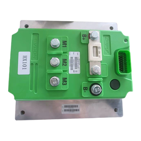
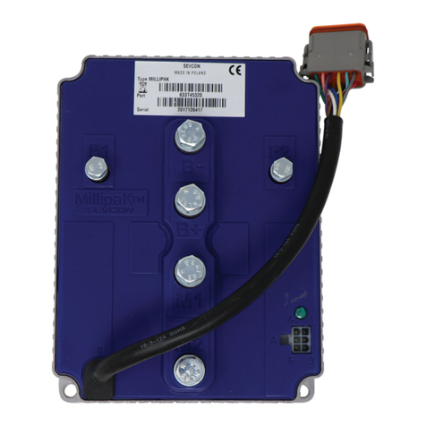
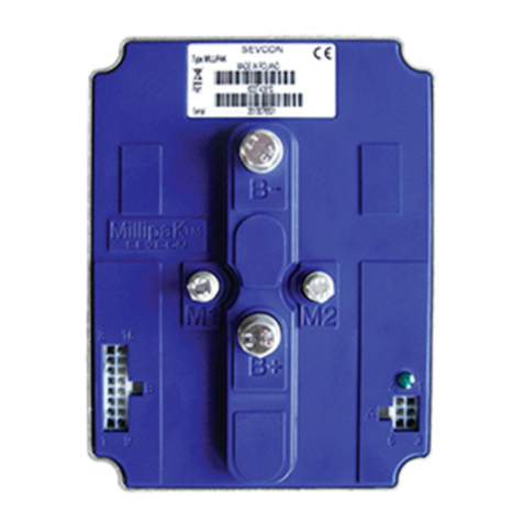
There are three mechanical package options (Figure 2) for the Gen4 controller at various voltage
and current ratings.
Size 2 models
Size 4 models
Size 6 models
Figure 2 Mechanical package options

About the Gen4
Doc. # 177/52701
Rev. 3.3
2-3
Intended use of the Gen4
The Gen4 motor controller can be used in any of these main applications for both pump and
traction control:
Counterbalanced, warehouse and pedestrian fork lift trucks
(Classes 1 to 3, FLT1, 2 & 3)
Airport ground support (AGS), including tow tractors
Utility vehicles
Burden carriers
Sweepers and scrubbers
Golf buggies/carts
Neighbourhood electric vehicles (NEV)
Scooters
Marine
Available accessories
The following accessories are available from Sevcon
Loose equipment kit (connectors and pins) for Gen4
CANopen Calibrator Handset
SmartView™ display
ClearView™ display
Hourmeters
Contactors
Fuses
Drive Wizard - PC based configuration tool
SCWiz –PC based motor characterisation tool

Doc. # 177/52701
Rev3
2-4
Overview of a truck drive system
Each traction or pump application requires a number of system components. The main
components (excluding control inputs such as throttle and seat switch) are shown in Figure 3. In
this example there are two controllers, a traction motor and a hydraulic pump, however all the
main components would be the same if controller 2 was also powering a traction motor.
Communication between the controllers is achieved using the CANopen protocol. This protocol
also allows Gen4 to communicate with other non-Sevcon, CANopen compliant devices.
Figure 3 Truck system components
Signal power for the internal control circuits and software is derived from the battery via the
control fuse and key switch as shown. No external in-rush current limiting is needed as long as
Gen4 is used to control the line contactor and hence the timing of its closure. The software
controls the start up sequence in this order:
1. Charge the input capacitors to within a user definable percentage (using 5820h) of battery
voltage (via the key switch signal line).
2. Close line contactor.
3. Generate output to the motor as demanded.
A line input fuse can be mounted on the body of the controller. The ‘B+’ terminal is a dummy
terminal. If the fuse is mounted elsewhere, connections from the battery positive are made to the
controller ‘+’ terminal see “On-board fuse mounting” section.
battery
Gen4 controller 1
Gen4 controller 2
motor
pump
B
-
CAN bus
3
ø
3
ø
key switch
-
+
isolator
control fuse
line contactor
M1 M2 M3
M1 M2 M3
B+
+
signals
B
-
B+
+
signals

About the Gen4
Doc. # 177/52701
Rev. 3.3
2-5
Principles of operation
Functional description
The main function of Gen4 is to control the power to 3-phase squirrel-cage AC induction or
PMAC motors in electric vehicles. Four-quadrant control of motor torque and speed (driving and
braking torque in the forward and reverse directions) is allowed without the need for directional
contactors. Regenerative braking is used to recover kinetic energy which is converted into
electrical energy for storage in the battery.
In a traction application control commands are made by the driver using a combination of digital
controls (direction, foot switch, seat switch, etc.) and analogue controls (throttle and foot brake).
The controller provides all the functions necessary to validate the driver’s commands and to
profile the demand for speed and torque according to stored parameters.
Throttle inputs can be configured as speed or torque demands with throttle-dependent speed
limits: in either case, a torque demand is continually calculated to take account of pre-set limits
on the level and rate-of-change of torque. The torque demand is used to calculate current
demands; that is, the controller calculates what currents will be required within the motor to
generate the required torque.
There are two distinct components of the current, known as the d-q axis currents, which control
current flow in the motor. The d-axis current is responsible for producing magnetic flux, but does
not by itself produce torque. The q-axis current represents the torque-producing current.
NOTE: When a vehicle is ready to drive, but no torque is being demanded by the driver, the
d-axis or magnetizing current will be present in the motor so that the vehicle will respond
immediately to a torque demand. To save energy the magnetizing current is removed if the
vehicle is stationary and no torque has been demanded after a set period.
Measured phase currents and current demands idand iq, the d-q axis currents, are used as part
of a closed-loop control system to calculate the necessary voltage demands for each phase of
the motor. Voltage demands are then turned into PWM demands for each phase using the
Space Vector Modulation (SVM) technique. SVM ensures optimum use of the power
semiconductors.
Power conversion section
The power conversion section of Gen4 employs a 6-switch MOSFET bridge operating at an
effective frequency of either 16 kHz or 24kHz ( equates to a PWM switching frequency of 8kHz
or 12kHz and is set via object 5830h). Excellent electrical and thermal efficiency is achieved by:
Minimization of thermal resistances.
Use of the latest MOSFET technology
Internal thermal protection (if temperatures are excessive, output torque is reduced).
Overcurrent protection using device characteristics.
Internal measurement of output current.
Overvoltage trip in the event of regenerative braking raising battery voltage to unsafe levels.

Doc. # 177/52701
Rev3
2-6
Dual traction motor
In the case of dual traction motors, there is additional processing of the associated steering
signal (from a potentiometer or switches) in order to generate separate torque demands for the
left and right motors of the vehicle. This allows the two motors to be operated at different speeds,
which greatly assists in turning the vehicle and prevents wheel scrub. After the torque demands
have been generated, the operation of each motor control system is as described in the case of
a single traction motor.
Pump motors
Pump motor control is similar to traction motor control, although motion is requested using a
different combination of switches.
Interfaces
In addition to its motor control functions, Gen4 offers many other functions designed to interface
with electric vehicles. A variety of digital and analogue input sources are supported, as listed in
‘Signal connections’ on page 3-14.
Voltage and current control of up to three contactors or proportional valves is provided by Gen4,
and includes built-in freewheeling diodes for spike suppression. All I/O on the Gen4 controller is
protected against short-circuit to the battery positive and negative terminals.
Connectivity and interoperability with other system devices (for example another Gen4 controller)
using a CANbus and the CANopen protocol is provided. In addition to in-service operation, the
CANopen protocol allows the controller to be commissioned using the Calibrator handset or
Sevcon’s DVT tool. In addition Sevcon’s SCWiz PC based tool provides the function to self-
characterize most induction motors and hence simplify the process of putting a new motor into
service.
For simple visual diagnosis of system faults and to monitor system status, a green LED is
provided on the body of the controller. It is continuously lit when there is no fault but flashes a
different number of times, in a repeated pattern, when there is a fault. The number of flashes
indicates the type of fault (see ‘’ on page 1).
Master-slave operation
The Gen4 controller contains both master and slave functions as shown in Figure 4. They
operate as follows:
Slave function: implements the CANopen Generic I/O Profile (DS401) and the Drives and
Motion Control Profile (DSP402).
Master function: implements vehicle functionality (traction and pump control) and CANopen
network management.

About the Gen4
Doc. # 177/52701
Rev. 3.3
2-7
Figure 4 Single controller
Torque mode
In this mode Gen4 maintains the motor torque output at a constant value for a given throttle
position. This is similar to DC motors (in particular, series wound DC motors) and provides a
driving experience like a car. To prevent excessive speed when the load torque is low, for
example when driving down hill, a maximum vehicle speed can be set.
Speed mode
WARNING: Speed mode (or speed control) is not recommended for on-highway vehicles
as it can cause the traction motor/wheel to remain locked or brake severely if the wheel is
momentarily locked due to loss of traction on a slippery surface and/or mechanical
braking.
In this mode Gen4 maintains the motor at a constant speed for a given throttle position as long
as sufficient torque is available. Speed mode differs from torque mode in that the torque value
applied to the motor is calculated by the controller based on the operator’s requested speed
(determined by throttle position) and the vehicle’s actual speed. This mode is useful where
accurate speed control is required irrespective of the motor torque.
Controller
tomotors, switches,
pedalsetc
CANopen
I/O
slave motor
slave
master
function

Doc. # 177/52701
Rev3
2-8
Safety and protective functions
General
WARNING: Electric vehicles can be dangerous. All testing, fault-finding and adjustment
should be done only by competent personnel. The drive wheels should always be off the
floor and free to rotate during the following procedures. The vehicle manufacturer's
manual should always be consulted before any operation is attempted.
WARNING: The battery must be disconnected before replacing the controller. After the
battery has been disconnected, wait 30 seconds for the internal capacitors to discharge
before handling the controller.
WARNING: Battery vent caps must be securely in place before connecting the controller
to a battery as an arc may occur due to the controller's internal capacitance when it is first
connected.
WARNING: If a PMAC motor is being used at the maximum motor speed the peak line to
line back emf must not exceed the non-operational voltage limit specified in (add ref to
section 4 input voltage table). The controller may be damaged if the back emf exceeds
this level.
WARNING: Do not tow vehicles that have PMAC motors, the motors act as generators and
may cause high currents to flow in the motor, controller or battery system. If towed at a
speed in excess of the vehicle rated speed the voltage generated by the motor may
damage the controller or battery.
WARNING: When a PMAC motor is acting as a generator, for example when braking or
driving down hill, the short circuit current must not exceed the controller current rating.
The short circuit current should be calculated for all vehicle speeds and must be less that
the controller current rating. If the current is greater than the controller current rating then
measures must be taken to protect the controller from the motor acting as a generator.
Possible measures include adding a disconnect switch between the motor and controller
on at least 2 out of the 3 phases, or adding fuses in each phase. Contact your local
Sevcon representative for further information and guidance.
CAUTION: Ensure that contactors with blow-out magnets are wired with the correct polarity to
their power terminals as indicated by the + sign on the top moulding.
Table of contents
Other Sevcon Controllers manuals

