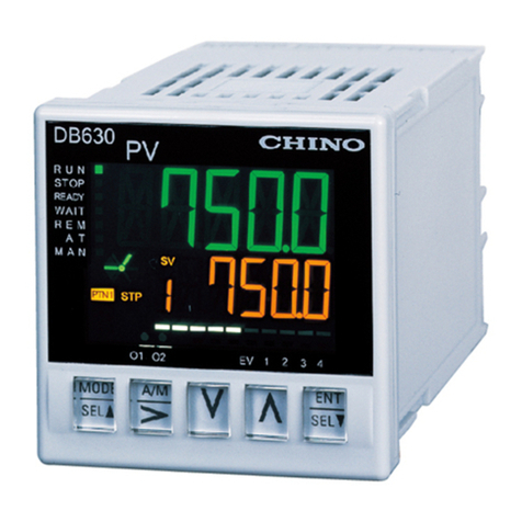
Chino CP350 Series User manual

INST.No. CP-GENERAL-EN-2
Digital Indicating Controller
CP350/CP370Series
[General ]

-1-
1. Introduction .............................................................................................................................................................2
2. For Safe Use of Product .........................................................................................................................................3
3. Installation and Mounting ........................................................................................................................................4
4. Wiring......................................................................................................................................................................6
5. Procedure of Initial Settings ....................................................................................................................................9
6. Front Panel............................................................................................................................................................10
7. Screen Configuration and Basics of Setting .........................................................................................................11
8. Operation Screen..................................................................................................................................................12
9. Setting Screen.......................................................................................................................................................14
10. Operation ..............................................................................................................................................................31
11. Detailed Functions Description .............................................................................................................................35
12. Model Code...........................................................................................................................................................44
13. Specifications........................................................................................................................................................45
14. Checking and Maintenance ..................................................................................................................................49
15. Troubleshooting ....................................................................................................................................................50
16. Parameter List ......................................................................................................................................................52
Table of Contents

-2-
Thank you for purchasing Digital Indicating Controller "CP series".
The generic name for a type with a front size of 48 x 96 is called "CP350" and that for a type with a front size of 96 x 96 is called
"CP370".
This manual is a "General" instruction manual. For specifications regarding communications, read "Communications"
instruction manual separately.
All information in this instruction manual is subject to change without prior notice.
1. Introduction
[For persons doing instrumentation, installation, and sales]
1. Before doing system design, read the instruction manual and have enough understanding of specifications and
handling of the product.
2. Be careful not to drop the product and break it.
3. Be sure to handover the instruction manual to the persons using the product.
4. When transporting the product, pack it in an exclusive packing box and then put it with cushions in another box.
[For users of the product]
1. Preserve the instruction manual until you scrap the product.
2. Write down the parameter contents set in the product and keep it for your record.
3. When not using the product for a long period, put it in an exclusive packing box and store at optimal temperature and in a
dust free good atmosphere.
Request
Confirm the following before using this product:
1. Confirm that the product specification (model code) is that of the model you purchase.
The model code is pasted on the side surface of the product and the packing box.
2. Two pieces of mounting brackets as standard accessories and an instruction manual are included in the package of the
product.
If you purchase additional accessories, confirm that they are included.
3. The protecting sheet is pasted on the front section of the product. When using the product, remove the sheet from it.
Before use
The following symbol marks are used for the product and in this instruction manual: Be sure to understand them
properly.
Used to draw the user's attention to the danger that can result in death or serious injury of the
involved person. It is also used for the precautions to avoid such an accident.
Used to draw the user's attention to the danger that can result in small injuries of the involved
person or damages of the peripheral instruments. It is also used for the precautions to avoid
such an accident.
Warning
Precautions
Symbol mark
This product is warranted for one year from the date of purchase.
However, the following cases are not included in the warranty even in the warranty period:
1. Mechanical failure caused by improper use or connection, or invalid repair or modification.
2. Mechanical failure caused by fire, earthquake, wind or flood, thunderbolt, or other extraordinary natural phenomena, or
pollution, salt water, harmful gas, abnormal voltage, or use of unspecified power.
3. Replacement of parts or accessories that have reached the end of their life.
Product warranty period

-3-
The product is a general product of system component type that is used by mounting it in a panel for instrumentation inside a
room. Do not use it in any other conditions. Due to the nature of the product, handling the product needs some expertise. For
the wiring and operation of the product, contact a professional having knowledge of instrumentation. It is also necessary for
users who actually use this product to read this instruction manual and have enough knowledge of various precautions and
basic operations.
2. For Safe Use of Product
1. Strictly observe the instruction manual
In order to use the product correctly and safely, make sure to follow this instruction manual.
The user is strongly recommended to read this manual carefully and gain comprehensive knowledge to avoid possible
problems before using the product.
2. Disclaimer of liability
Regardless of errors or shortage in writing in this instruction manual or the use conditions of this product, CHINO is not
responsible for any injuries, damages, or loss of profits resulted from improper use of this product.
3. Install safety instruments on the system side
When using this product for a final product system, and if a failure in the product or its peripheral devices may cause
serious damages to the final product, always install safety instruments and develop a fail-safe design for the final product
system to avoid such damages. Never use this product for critical facilities that are related to human life, atomic energy,
aviation, etc.
When power is supplied, sometimes the output related signal may be momentarily output until the product is starting
normally. Implement the countermeasures against erroneous output as per the requirement by using external circuit.
4. Need for basic knowledge on the controller
To handle the product, the basic knowledge related to the controller and the control equipment is needed. This
instruction manual is intended for a knowledgeable person with basic knowledge related to them. This product should be
used only by a person with the enough knowledge on the controller.
5. Confirm the power supply voltage and wiring
Before starting to supply power to the product, check to see that the wiring for the power supply voltage and
power-supply frequency and the product is correct and grounding is established. And also make sure that the grounding
is established on the system side.
6. Protection of terminal section
To avoid an electric shock, provide the terminal section of the product with a safety measure by the system side that
prevents the user from directly touching the terminal section. However, an exclusive terminal cover for the product is
available optionally.
7. Actions in the case of suspicion
If there is an offensive smell, strange noise or smoke or if the temperature increases abnormally, it is very dangerous,
hence immediately turn power off.
8. Prohibit repairing and modifying
When repair or modification is needed, contact the dealer or our sales office. Only our authorized engineers are allowed
to repair or modify the product. Never put your hands or tools inside the product or draw out the internal unit. If you do so,
you may get an injury or an electric shock.
Important
Warning

-4-
3 - 1. External Dimensions
[CP350] [CP370]
3 - 2. Panel Cutout Size
[CP350] [CP370]
3 - 3. Installation Conditions
2. For Safe Use of Product
3. Installation and Mounting
[Single unit mounting]
92 + 0.8
0
120
120
96×N-4
N: Number of
mounted units
+ 2
0
92
+ 0.8
0
92
+ 0.8
0
[Closed installation]
70
120
45 + 0.6
0
48×N-3
N: Number of
mounted units
+ 2
0
92
+ 0.8
0
92
+ 0.8
0
[Single unit mounting] [Closed installation]
Precautions
1. Environment
•In a room, away from direct sunlight, and less variation in temperature and wind. Away from heat remaining and
well-ventilated.
•No vibrations and shocks, away from water and oil, and away from condensation.
•Under "Excess voltage category II, Pollution level 2" based on EN standards.
2. Atmosphere
•Away from strong noise, static electricity, electric field, magnetic field, induction, steam, salt, oil, etc.
•Away from dust, conductive material (carbon, iron, etc.), corrosive gas, ignition gas, etc.
3. Installation and Mounting
•Installation height is at an altitude 2,000 m or less.
•Use a steel with the thickness of 1 to 5 mm for the mounting panel.
•Mounting position is approximately 1.5 m (eye level). Mounting orientation is ±10 ° or less in longitudinal tilting and
±10 ° or less in lateral tilting.
•Do not cover the vents on the top and bottom of the product.
•Install the product away from noise source and heat generating source.
Installation conditions
Precautions
48
Terminal cover
(optional item)
132
91×44
94
96
111
7
Mounting bracket
100
132
91×91
94
96
7100
Mounting
bracket
Terminal cover
(optional item)
111
96

-5-
3 - 4. Panel Mounting Method
(1) Insert the product into a rectangle hole of
the panel. In the case of water-proof
specifications, insert the product into the
rectangle hole after mounting the
provided water-proof packing to the case.
(2) Insert the mounting hooks of the provided
mounting bracket into the mounting holes
on the top and bottom of the product and
push the product into the panel.
(3) In the case of water-proof specifications, use the
provided screws to mount the mounting brackets.
The screwing torque is 0.5 to 0.7 N•m.
(4) In the case of water-proof specifications, confirm
that the water-proof packing is mounted properly
between the product and the panel. If there is a
shift or gap between them, the water-proof function
does not work properly.
(5) In the case of the closed installation, the water-proof function for the water-proof product does not work.
Make sure to use the water-proof product for the single unit mounting.
In the case of the closed installation, because the ambient temperature rises up to 40 °C, avoid rising to high
temperatures.
Panel
[Mounting bracket]
Mountin
g
hook
Water-proof screw
Mounting holes on the top
Mounting holes on the bottom
Water-proof packing

-6-
4 - 1. Terminal Board Diagram
[CP350] [CP370]
4 - 2. Basic Wiring
4. Wiring
A
BC
A
BC
1. Depending on the product specification (model
code), no terminal screw is provided for some
positions.
2. Because the function may vary depending on the
product specification even with the same terminal
number, confirm the model code of your product.
Additionally, confirm the terminal label pasted on the
side surface of the product.
Confirmations before wiring
For the relay contact protection, be sure to apply the load
on the output terminal of on-off pulse type and SSR drive
pulse type or the relay output terminal of event output via
the buffer relay as shown in the figure on the right.
In addition, be sure to connect a contact protection element
for relay contact protection and for noise reduction.
connect a contact protection element.
Similarly, when using an open collector output terminal to
connect a buffer relay, connect a contact protection
element.
Two types of contact protection elements are available
optionally.
Select one depending on your usage.
Name Model Specifications Open/
close current Leakage current
Contact protection
element for light load CX-CR1 0.01 µF+120 Ω0.2 A or less Approx. 2 mA
Contact protection
element for heavy load CX-CR2 0.5 µF+47 Ω0.2 A or more Approx. 55 mA
As leakage current flows when using AC power supply load to connect the contact protection element, select a contact
protection element depending on the open/close current for the load.
The external CT used for heater snapping wire alarm
is sold separately and thus purchase it separately.
"CTL-6-S-H" made by U-RD
*Japanese-made product
Precautions
Basic wiring
Buffer relay
Relay output Z
Power
supply
Load
CT input
terminal
Connected to
heater
External CT
Z: Contact protection
element

-7-
4 - 3. Terminal Function Diagram
Terminal
number A row (standard section) : Measurement input + event output + control output 1 + power supply
1Unconnected AUnconnected
2+B+
3
Measurement
input Thermocouple
-
Resistance
thermometer B
Voltage/Current
-
4EV1 (Relay output: N.O.)
5EV2 (Relay output: N.O.)
6
Event output
EV1/EV2 COM (Relay output: COM)
7N.O. +
8
Output 1
(Control output 1)
ON-OFF pulse type
(Relay output) COM
Current output type
SSR drive pulse type
Voltage output type -
9L
10 Power supply
N
(1) When input type is DC current (4 to 20 mA), connect a shunt resistor (250 Ω) between the terminal number 2 and 3, and
perform the measurement at the conversion equivalent value of DC current voltage 1 to 5 V. An exclusive shunt resistor
for the product is available optionally. (model: EZ-RX250)
Terminal
number
B row (option section) : Additional event open collector output 3 points
+ additional external input 5 points
11 EV5 (Open collector output)
12 EV6 (Open collector output)
13 EV7 (Open collector output)
14
Event output
COM (Open collector output: COM) for EV5/EV6/EV7
15 DI2
16 DI3
17 DI4
18 DI5
19 DI6
20
External input
COM for DI2/DI3/DI4/DI5/DI6
(2) Note: The additional event output for B row is an open collector output.
Terminal
number
C row (option section) : Communications RS-485 + external input 1 point + heater snapping wire alarm
+ transmission signal output + control output 2
21 RS-485 SA
22 RS-485 SB
23
Communications
RS-485 SG/ COM for DI1
24 External input DI1
25 CT input
26
Heater snapping
wire alarm (CT) CT input
27 Transmission signal output +/EV4 (Relay output: N.O.)
28
Transmission signal
output
Event output Transmission signal output -/EV4 COM (Relay output: COM)
29 N.O. +
30
Output 2
(Control output 2)
Event output
ON-OFF pulse type
EV3
(Relay output) COM
Current output type
SSR drive pulse type
Voltage output type -

-8-
4 - 4. Precautions for Wiring
1. Turn off power
Make sure to turn off the power supply before doing the wiring.
2. Strictly observe rating range
Strictly observe the rating range of the power supply terminal and input/output terminal. If an excessive voltage or
current is applied to the input/output terminal of the product, the product may be damaged, deteriorated, or
malfunction. Before starting to supply power to the product, check if all the wiring for the product are correct and
isolated.
3. Supply high quality power
To prevent failure or malfunction of the product, connect a high quality single phase power supply with little noise
and distortion. If the noise is loud, insert the noise filter, insulation transformer etc.
4. Specified wires, crimp style terminals, and tightening torque
Use the following wires and crimp style terminals with insulating sleeve for connection to the main terminal:
Wire Crimp style terminal with insulating sleeve Tightening
torque
600 V vinyl insulation
electric line
• IEC227-3
• ANSI/UL817
• CSA C22.2 No.49
• AWG16-22
In order to ensure safety, make sure to use O-chip terminal for
the power supply terminals and relay output terminals.
0.6 to 0.8 N•m
5. Connection for measurement input terminals
For a thermocouple, use directly a thermocouple cable or a compensation lead wire. For a resistance thermometer,
use 3-core cable with the same resistance value for each cable.
Parallel connection of the measurement input terminal is not allowed. Parallel connection may generate
measurement errors, inhibits stable control of the system, and result in an entire system failure.
6. Connect over current protection device
The product does not have a power switch.
For connection to the power supply terminal of the
product, make sure to connect the over current
protection device and switch that conforms to the
rating as shown in the figure on the right.
7. Take actions for unused terminal
Do not connect anything to the unused terminal. Never use it for a relaying terminal.
8. Protection of terminal section
To avoid an electric shock, provide the terminal section of the product with a safety measure by the system side
that prevents the user from directly touching the terminals. The exclusive terminal cover for the product is available
optionally.
Within 3 m
Product
Over circuit protection device Switch
Power
supply
A
B
A
B
[Y-chip]
[O-chip]
A: 3.7 mm or
more
B: 7.0 mm or
less
Precautions for wiring
Precautions

-9-
This section describes the procedure of minimum required initial settings. Refer to section "6." to "9." and then set the required
parameters depending on the specifications and control conditions for the product.
: Always set : Set as required
5 - 1. For Constant-value Control
(1) Set the input type according to the sensor.
↓
(2) Set measurement range that is to be actually used.
↓For linear, set standard range-equivalent.
(3) For linear, set a scale.
↓
(4) Select the control operation.
↓
(5) Set SV.
↓
(6) Set PID.
If PID constant does not know in advance,
↓retrieve the optimum PID constant from the trial
operation.
(7) Select the parameter group No. for which the SV and
PID was set.
↓
(8) Confirm RUN status.
5 - 2. For Program Control
(1) Refer to section "5 - 1.".
↓
(2) Refer to section "5 - 1.".
↓
(3) Refer to section "5 - 1.".
↓
(4) Refer to section "5 - 1.".
↓
(5) Set a program pattern.
↓
(6) Refer to section "5 - 1.".
↓
(7) Select the pattern No. for which the program pattern was set.
↓
(8) Perform RUN operation.
5. Procedure of Initial Settings
(1) Set "INPUT TYPE" : mode 5
(2) Set "MEASUREMENT RANGE" : mode 5
(3) Set "LINEAR SCALE" : mode 5
(4) Select "CONTROL OPERATION" : mode 6
(5) Set "SV" : mode 3
(6) Set "PID" : mode 5
(7) Select "PARAMETER GROUP No."
: Operation screen
(8) Switch to "RUN" : Operation screen
(1) Set "INPUT TYPE" : mode 5
(2) Set "MEASUREMENT RANGE" : mode 5
(3) Set "LINEAR SCALE" : mode 5
(4) Select "CONTROL OPERATION" : mode 6
(5) Set "PROGRAM PATTERN" : mode 2
(6) Set "PID" : mode 5
(7) Select "PATTERN No." : Operation screen
(8) Operate "PROGRAM DRIVE"
: Operation screen

-10-
6 - 1. Display
[CP350] [CP370]
Name Description of function
Upper 4-digit
(7seg.LED)
• At the operation screen, usually displays PV.
• At the setting screen, usually displays setting parameter name.
Lower 4-digit
(7seg.LED)
• At the operation screen, usually displays SV and OUT (MV).
• At the setting screen, usually displays set value and setting item.
S V
(Status LED)
• At the operation screen, lights when SV is displayed in the lower 4-digit.
• Blinks during the SV ramp operation of constant-value control.
OUT
(Status LED)
• At the operation screen, lights when OUT (MV) is displayed in the lower 4-digit.
EV1
(Status LED)
• At initial status, lights when event output "EV1" is ON.
• Any status can also be assigned as "Status 1".
EV2
(Status LED)
• At initial status, lights when event output "EV2" is ON.
• Any status can also be assigned as "Status 2".
A T
(Status LED)
• At initial status, lights during auto tuning.
• Any status can also be assigned as "Status 3".
RUN
(Status LED)
• At initial status, lights in the case of RUN of constant-value control or program control.
• Any status can also be assigned as "Status 4".
OUT
(Status LED)
• At initial status, lights according to output status (0 %: off, 100 %: on).
• Any status can also be assigned as "Status 5".
MAN
(Status LED)
• At initial status, lights in the case of manual operation (manual output).
• Any status can also be assigned as "Status 6".
6 - 2. Key Operation Section
key Name Description of function
mode-key • Uses when switching screen between the operation screen and setting screen or switching
a screen between setting screens within the mode screen.
down-key • Uses when switching mode screen and changing setting in the setting screen.
up-key • Uses when switching mode screen and changing setting in the setting screen.
enter-key • Uses when switching a screen between setting screens within the mode screen.
• Uses when registering the setting change in the setting screen.
5. Procedure of Initial Settings
6. Front Panel

-11-
7 - 1. Display Configuration
When turning on the power supply, the operation screen is displayed after initial display is completed. The setting screen for
parameters is separated into more than one screen from mode 0 to mode T and thus they result in an easy-to-understand matrix.
The figures below shows the transitions of the screen configuration for the operation screen and setting screen and the display of
LED 4-digit on the upper and lower rows.
In the setting screen if no key operation is done for more than 3 minutes, it automatically returns to the operation screen except
for special screens. Note that the displayed setting screen varies depending on the specifications (model code) for the product.
7 - 2. Basics of Setting
(1) The setting screen is separated into more than one screen according to mode. Confirm that the setting screen you want to
invoke is included in what number of which mode.
(2) Select the ' ' key to switch between the operation screen and mode screen, the ' • ' key to select a mode
No., and the ' • ' key to select the setting screen, respectively.
(3) In the setting screen, numeric value is changed and field is selected by using the ' • ' key and settings are
registered by pressing the ' ' key being changed. However, for the setting change, dots are blinking when a change is
performed, dots light out when the ' ' key is pressed to complete the setting change.
7 - 3. Screen Character Font
ABCDEFGHIJKLMN
OPQRSTUVW X YZ
7. Screen Configuration and Basics of Setting
[ Operation screen ] [ Setting screen ]
PV+SV
mode 0
mode 1
mode T

-12-
[PV/SV]
Displays the current PV on the upper and the current SV on the lower.
When "Multiple display" is selected for "Operation screen SV display", specific
operation screen is displayed at regular intervals.
Executing SV can be changed during operation.
When SV is changed during ramp operation, numeric value is changed after current
SV setting value is displayed by using key operation.
The setting range falls within the SV limiter range.
The change of setting in this screen is reflected in the original setting value.
[PV/PATTERN STEP]
Displays the current PV on the upper and the current pattern No. (left side) and step
No. (right side) on the lower.
This screen is displayed only at the program control.
[PV/STEP TIME]
Displays the current PV on the upper and the current step time on the lower.
This screen is displayed only at the program control.
[PV/OUT1]
Displays the current PV on the upper and the output value at the current output 1
(control output 1) on the lower.
[PV/OUT2]
Displays the current PV on the upper and the output value at the current output 2
(control output 2) on the lower.
For distinguishing from operation screen "PV/OUT1", "OUT2" is displayed at regular
intervals.
This screen is displayed only when the control output 2 is added.
[AUTO/MAN OUTPUT
SWITCHING]
Used for switching between automatic output operation (AUTO) and manual output
operation (MAN).
• '': Automatic output operation (AUTO)
• ' ': Manual output operation (MAN)
Automatic output operation (AUTO) includes preset output, PV abnormal output, and
output of RESET program control (0%).
The front status "MAN" lights at manual output operation.
The output value of the manual output operation (MAN) is set in the operation screen
for the control output.
Switching is simultaneously performed both at the output 1 (control output 1) and at
the output 2 (control output 2).
[EVENT STATUS]
Displays the current event status on the lower with 7-segment 4-digit.
• '' (upper of 1,000-digit) : EV1 is ON
• ' ' (upper of 100-digit) : EV2 is ON
• ' ' (upper of 10-digit) : EV3 is ON
• ' ' (upper of 1-digit) : EV4 is ON
• '' (lower of 1,000-digit) : EV5 is ON
• ' ' (lower of 100-digit) : EV6 is ON
• ' ' (lower of 10-digit) : EV7 is ON
Only for the set alarm events (except for timer 1, timer 2, and FAIL signal) from EV1 to
EV4 in this screen, forcibly change the event status to OFF(RESET) by using key
operation.
• '': Alarm event RESET
When the event output is added depending on the specifications (model code), actual
output is turned ON/OFF from the terminals according to the event status in this
screen.
8. Operation Screen

-13-
[TIMER 1 TIME]
Displays the timer 1 elapsed time on the lower.
This screen is displayed only when the timer 1 function is selected.
[TIMER 2 TIME]
Displays the timer 2 elapsed time on the lower.
This screen is displayed only when the timer 2 function is selected.
[CT MEASUREMENT VALUE]
Displays the current CT measurement value required for heater snapping wire alarm
and heater over current alarm on the lower.
This screen is displayed only when heater snapping wire alarm is added.
[AUTO TUNING]
Screen for executing PID auto tuning.
• ' ': End of auto tuning
• '': Auto tuning for output 1 (control output 1)
• '': Auto tuning for output 2 (control output 2)
Some items may not be displayed depending on the specifications (model code).
During run, a screen is displayed from '' to '' according to progress.
If aborting the auto tuning during run, change to ' '.
[PATTERN REPEAT]
Displays the number of runs of the current pattern repeat on the lower.
This screen is displayed only at the program control.
[PATTERN No. SELECT]
Screen for executing the program pattern select.
Displays the currently selected pattern No.
During RESET, select a pattern No. to run the set pattern No. '' to ''.
[PROGRAM DRIVE]
Screen for executing the program control.
Displays the currently running program control status.
The program control status can be changed by using key operations.
• '': Reset program (RESET)
• ' ': Run program (RUN)
• '': Stop program (STOP)
• ' ': Advance program (ADVANCE); Advance one step for each key operation
[RUN/READY SWITCHING]
Screen for executing constant-value control.
Displays the currently running constant-value control status.
The constant-value control status can be changed by using key operations.
• ' ': Run operation
• '': Stop operation
[PARAMETER GROUP No.
SELECT]
Screen for executing parameter group selection.
Select a group No. to run between the set group No.'' and ''.

-14-
9 - 1. mode 0
[mode0]
The start screen of mode 0.
Mode 0 is used for setting the main parameters during execution.
For displaying the executing parameter group No., the executing parameter group No.
is displayed at regular intervals on the lower.
[Executing SV]
SV can be changed during execution.
The setting range falls within the SV limiter range.
The change of setting in this screen is reflected in the original setting value.
[Executing step time]
For program control (RUN/STOP), the step time can be changed during execution.
The setting range is 00:00 to 99:59.
The change of setting in this screen is reflected in the original setting value.
This screen is displayed only at the program control.
[Executing event: EV1]
The event "EV1" can be changed during execution.
The change of setting in this screen is reflected in the original setting value.
[Executing event: EV2]
The event "EV2" can be changed during execution.
The change of setting in this screen is reflected in the original setting value.
[Executing event: EV3]
The event "EV3" can be changed during execution.
The change of setting in this screen is reflected in the original setting value.
[Executing event: EV4]
The event "EV4" can be changed during execution.
The change of setting in this screen is reflected in the original setting value.
[Executing PID: P]
"P" of PID can be changed during execution.
The setting range is 0.0 to 999.9 %. When P is set to 0.0 %, two-position control is
performed.
The change of setting in this screen is reflected in the original setting value.
[Executing PID: I]
"I" of PID can be changed during execution.
The setting range is 0 (∞) to 9999 seconds.
The change of setting in this screen is reflected in the original setting value.
[Executing PID: D]
"D" of PID can be changed during execution.
The setting range is 0 (OFF) to 9999 seconds.
The change of setting in this screen is reflected in the original setting value.
9. Setting Screen

-15-
[Executing output limiter:
Lower limit]
The lower limit of the output limiter can be changed during execution.
The setting range is -5.0 to 100.0 %.
The change of setting in this screen is reflected in the original setting value.
[Executing output limiter:
Upper limit]
The upper limit of the output limiter can be changed during execution.
The setting range is 0.0 to 105.0 %.
The change of setting in this screen is reflected in the original setting value.
[Executing output preset]
The output preset can be changed during execution.
The setting range is -5.0 to 105.0 %.
The change of setting in this screen is reflected in the original setting value.
9 - 2. mode 1
[mode1]
The start screen of mode 1.
Mode 1 is used for setting the parameters dedicated for constant-value control.
[SV ramp: Up]
Set the up ramp of the SV ramp operation.
• ' ': Up ramp operation OFF.
• ' ': Up ramp operation ON.
- The setting range is 1 to 9999/minute.
''
[SV ramp: Down]
Set the down ramp of the SV ramp operation.
• ' ': Down ramp operation OFF.
• '': Down ramp operation ON.
- The setting range is -1 to -1999/minute.
''
[PV start for constant-value
control]
Turn ON/OFF the PV start for constant-value control.
• ' ': PV start operation OFF
• ' ': PV start operation ON
[Event operation at READY]
Turn ON/OFF the event operation when the constant-value control is in the READY
state.
• '': Event operation ON
• ' ': Event operation OFF
1. Program Function
If the tenth digit of model code of a product is "P", the product has program function. Only a product with this type of
model code allows you to switch between constant-value control and program control.
2. Limitation of Setting Range
For the parameters for numeric settings, there exists a limitation on the range of numeric that can be set.
For example, when setting SV, note that there is a mutual relationship such that the setting range of SV falls within the
SV limiter range, and the SV limiter range falls within the measurement range.
Precautions while setting I

-16-
9 - 3. mode 2
[mode2]
The start screen of mode 2.
Mode 2 is used for setting the parameters dedicated for program control.
This mode is displayed only when a function is added.
[Program pattern]
Set a program pattern.
This is the initial screen for setting a program pattern.
For details of settings, refer to "9-4. Program Pattern Setting".
[Program run]
Turn ON/OFF the program control.
• ' ': Program control is turned ON (constant-value control OFF)
• ' ': Program control is turned OFF (constant-value control ON)
Switch between program control and constant-value control.
[Program time unit]
Select a time unit for a specific program pattern.
• ' ': Hours-minutes
• ' ': Minutes-seconds
Setting change is valid during RESET at constant-value control or program control.
When the setting is changed during RUN or STOP, forcibly RESET the program
control.
[SV at RESET]
Set the SV of program control during reset.
SV during RESET has no relation with actual program control. When program control
is in RESET, sets the value that is output to SV transmission of transmission signal
output and communication digital transmission output.
[PATTERN REPEAT]
Set the number of times of repeating program control.
Set the overall number of times of repetition, including the cases when a program
pattern is connected (linked).
[Operation Screen Time
Display Type]
Select the type of displaying the step time on the operation screen "PV/Step time".
• '': Display the step remaining time
• '': Display the step elapsed time
[Pattern clear]
Clear the program pattern that is set.
• ' ': Not executed (exit)
• '' - '': The selected individual patterns are cleared
• ' ': All patterns are cleared at one time
1. Change in Key Parameters Settings
If the settings of key parameters such as input type or basic event functions are changed, the settings such as setting
values and decimal point position that are related to those key parameters are automatically changed or initialized on
other setting screens. If you changed the settings of key parameters, be sure to check the set contents of other setting
screens.
2. Precautions When Setting Step Time of Program Pattern to "00:00"
When setting a program pattern, you can set the step time to "00:00" in order to start the SV of the next step instantly.
For the step for which the step time is set to "00:00", the arithmetic processing (control, event) of each step are not
executed.
In addition, for a continuous step, it is prohibited to set the step time to "00:00", because it may cause an error.
Precautions while setting II

-17-
9 - 4. Program Pattern Setting
•From pattern No. 1 to
4, select the pattern
No. to be set
↑selectable
•For the selected
pattern No., select the
step No. to be set
↑selectable
•For the selected pattern
No., the parameter
mode related to exiting
the program.
Total number ↑
of ste
p
s + 1
• For the selected pattern
No., set the operation of
control output 1 when
exiting the program.
: control
continued
: output 0.0 %
•For the selected step
No., set the SV.
•For the selected pattern
No., set the total number
of steps.
•The setting range is 1 to
12.
• For the selected pattern
No., set the connection
destination.
: not connect
: set the
- patternNo.
to connect
• For the selected step No.,
set the parameter group
No.
• The setting range is 0 to
8. 0 means the group No.
of the previous step is
continued.
• For the selected
pattern No., set the
start SV.
• For the selected pattern
No., set the operation of
control output 2 when
exiting the program.
: control
continued
: output 0.0 %
• This screen is displayed
only when the control
output 2 is added.
• For the selected step
No., set the time.
• The setting range is
00:00 to 99:99.
Setting 00:00 is not
allowed for
continuous step.
• For the selected
pattern No., turn
ON/OFF the PV start
operation.
: PV start OFF
: PV start ON
[ Program pattern ]
Initial screen
[ PTN1/STEP00 ]
Initial screen
[ PTN1/STEP01 ]
Initial screen
[ PTN1/End setting ]
Initial screen
[ PTN1/STEP00 ]
Setting screen of number of steps
[ PTN1/STEP01 ]
Setting screen of SV
[ PTN1/End Step ]
Setting screen of control output 1
[ PTN1/STEP00 ]
Setting screen of PV start
[ PTN1/STEP01 ]
Setting screen of time
[ PTN1/End Step ]
Setting screen of control output 2
[ PTN1/STEP00 ]
Setting screen of start SV
[ PTN1/STEP01 ]
Setting screen of parameter group No.
[ PTN1/End Step ]
Setting screen of destination pattern
• For each step from step No. 01 to final step No. of the selected pattern
No., repeat the process of setting SV, time, and parameter group No.
Program pattern setting is complete

-18-
9 - 5. mode 3
[mode3]
The start screen of mode 3.
Mode 3 is used for setting the eight types of parameter groups.
[Parameter group No.]
Select the parameter group No. to set from No. 1 to 8.
The No. selected here becomes the No. of all subsequent setting screens.
[SV for constant-value control]
Set the SV for constant-value control of the selected parameter group No.
The setting range falls within the SV limiter range.
[Event : EV1]
Set the value of the event "EV1" of the selected parameter group No.
[Event : EV2]
Set the value of the event "EV2" of the selected parameter group No.
[Event : EV3]
Set the value of the event "EV3" of the selected parameter group No.
[Event : EV4]
Set the value of the event "EV4" of the selected parameter group No.
[PID: P]
Set "P" of PID of the selected parameter group No.
The setting range is 0.0 to 999.9 %. When P is set to 0.0 %, two-position control is
performed.
[PID: I]
Set "I" of PID of the selected parameter group No.
The setting range is 0 (∞) to 9999 seconds.
[PID: D]
Set "D" of PID of the selected parameter group No.
The setting range is 0 (OFF) to 9999 seconds.
[Output limiter: Lower limit]
Set the lower limit of the output limiter of the selected parameter group No.
The setting range is -5.0 to 100.0 %.

-19-
[Output limiter: Upper limit]
Set the upper limit of the output limiter of the selected parameter group No.
The setting range is 0.0 to 105.0 %.
[Output preset]
Set the output preset of the selected parameter group No.
The setting range is -5.0 to 105.0 %.
The output preset is the output value without deviation during P control or the initial
output value of I calculation after turning the power on during PID control or after
switching to RUN in RESET of program control.
9 - 6. mode 4
[mode4]
The start screen of mode 4.
Mode 4 is used for setting the parameters of event.
[Event No.]
Select the event (EV) No. to set from EV1 to EV7.
The EV No. selected here becomes the EV No. of all subsequent setting screens.
[Basic event functions]
Set the basic event functions of the selected event No.
Functions settable only for EV1 to EV4 (Alarm event)
• ' ': Absolute value alarm high limit
• ' ': Absolute value alarm low limit
• ' ': Deviation alarm high limit
• ' ': Deviation alarm low limit
• '': Absolute value deviation alarm high limit
• '': Absolute value deviation alarm low limit
• '': Output value alarm high limit
• '': Output value alarm low limit
•' ': Heater over current alarm
•' ': Heater snapping wire alarm
• '': Timer 1
• '': Timer 2
• '': FAIL signal
Functions settable for all event EV1 to EV7 (Status event)
• ' ': Event operation OFF
• '': RUN status of constant-value control
• '': Preset output
• ' ': Remote SV operation of constant-value control
• '': SV moving up
• '': SV moving down
• '': Step switch signal of program control
• ' ': Step 1 signal of program control
• ' ': Step 2 signal of program control
• ' ': Step 3 signal of program control
• ' ': Step 4 signal of program control
This manual suits for next models
1
Table of contents
Other Chino Controllers manuals

Chino
Chino JU Series User manual

Chino
Chino DB600 Series User manual

Chino
Chino KP3000 User manual

Chino
Chino LT300 Series User manual

Chino
Chino LT830 Series User manual

Chino
Chino GT120 Series User manual

Chino
Chino KP1000 User manual

Chino
Chino DB600 Series User manual

Chino
Chino DB630E User manual

Chino
Chino JW Series User manual
Popular Controllers manuals by other brands

Hayes
Hayes 81725 Operation manual

Phoenix Mecano
Phoenix Mecano Elodrive ANT-04C1E quick start guide

Leightronix
Leightronix MINI-T-NET Installation quick guide

Woodward
Woodward TecJet 52 Installation and operation manual

PARCOL
PARCOL 1-X-290 Series instruction manual

Epson
Epson S1D16000 Series Technical manual