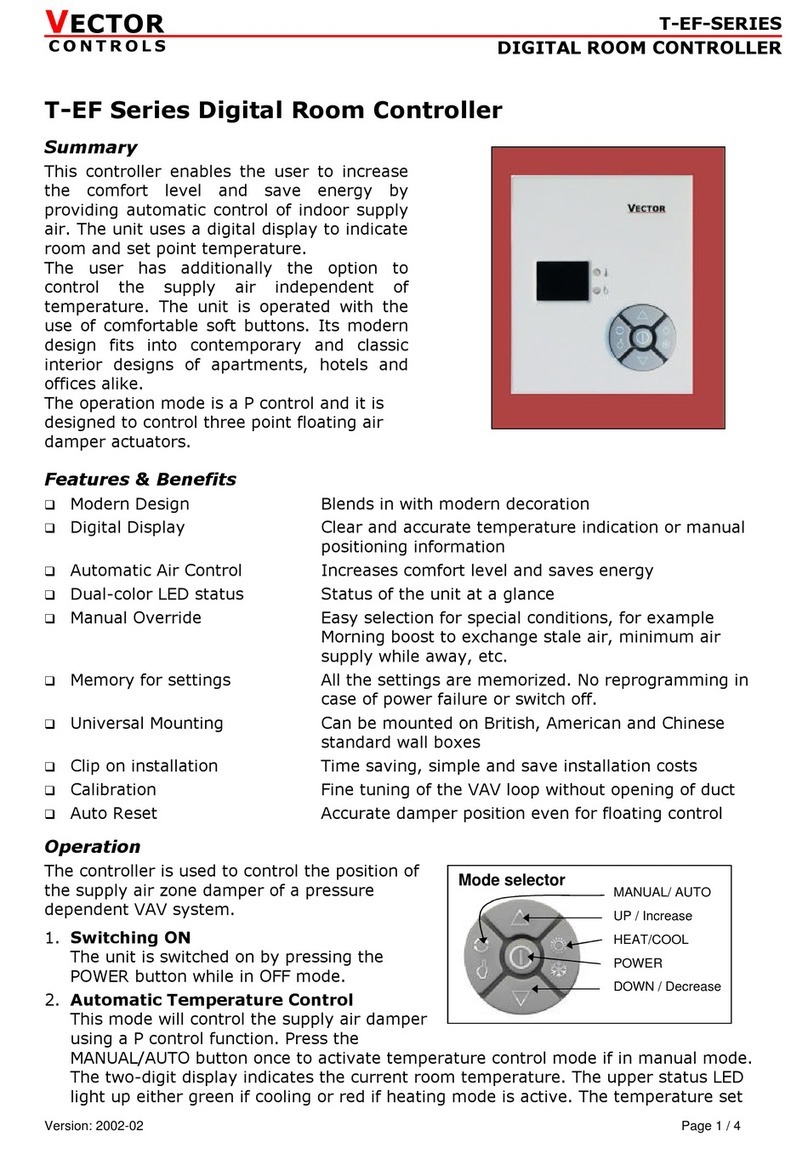
VECTOR CONTROLS TCX2 Operational manual

TCX2-40863
PRODUCT DATA SHEET
Doc: 70-00-0174C, 20221118 © Vector Controls GmbH, Switzerland Page 1-10
Subjects to alteration www.vectorcontrols.com
VECTOR
Universal Programmable Controller TCX2
The TCX2 is a programmable universal controller with communication capabilities. Each control loop may use 2 PI
sequences and 6 binary stages. The TCX2 uses the universal X2 operating system. Serial communication options are
realized with Modbus RTU/ASCII and BACnet MS/TP. There is also a Wi-Fi and an Ethernet communication option available
which supports Modbus TCP and BACnet IP. An embedded webserver provides a web interface to operate the controller or
change the connection settings. Complete parameter sets may be copied by use of an accessory called AEC-PM1 or
exchanged with a PC using an RS485-USB converter, Wi-Fi or Ethernet communication and the EasySet program.
Functions
•4 universally configurable control loops:
oFunctions for dehumidifying, set point shift and cascade control
oMultiple auxiliary functions: heat-cool auto changeover, automatic enable, set point compensation
oFree heating and cooling with economizer function based on enthalpy or temperature
oDifferential, averaging, min and max functions, enthalpy and dew point calculations
oTransmitter function for inputs and set points
•8 selectable universal inputs (VDC, mA, NTC)
•3 universal analog outputs (VDC, mA) and 6 relays with each a normally open contact (SPST)
•8 freely assigned alarm conditions, selectable state of outputs on alarm condition
•Power cap protected real-time clock with 48hr power backup
•7-day programmable schedules, with options including change of set points and direct position of manual outputs
•Password protected programmable user and control parameters
•Peer to peer communication to optional X2 operation terminal OPxx-VC
•Communication over Modbus, BACnet, Ethernet or Wi-Fi (optional interface required)
•Webserver that supports TCX2 operation trough mobile devices or EasySet IP access (Ethernet or Wi-Fi interface
required)
Wi Fi

TCX2-40863
PRODUCT DATA SHEET
Doc: 70-00-0174C, 20221118 © Vector Controls GmbH, Switzerland Page 2-10
Subjects to alteration www.vectorcontrols.com
VECTOR
Types and Ordering
Product Name
Product No.
Loop
UI
DO
AO
Functions
TCX2-40863
40-110032
4
8
6 Relays
3
OP
=
With display
MOD
=
Communication with Modbus RTU or ASCII
BAC
=
Communication with BACnet MS/TP
WEM
=
Com. with Modbus TCP over Wi-Fi with ext. antenna
WEB
=
Com. with BACnet IP over Wi-Fi with ext. antenna
ETM
=
Communication with Modbus TCP over Ethernet plug
ETB
=
Communication with BACnet IP over Ethernet plug
TCX2-40863-OP
40-110036
TCX2-40863-MOD
40-110077
TCX2-40863-OP-MOD
40-110078
TCX2-40863-BAC
40-110079
TCX2-40863-OP-BAC
40-110080
TCX2-40863-WEM
40-110117
TCX2-40863-OP-WEM
40-110133
TCX2-40863-ETM
40-110118
TCX2-40863-OP-ETM
40-110134
TCX2-40863-WEB
40-110126
TCX2-40863-OP-WEB
40-110135
TCX2-40863-ETB
40-110127
TCX2-40863-OP-ETB
40-110136
UI = Universal inputs, DO = Digital outputs, AO = Analog outputs
Accessories
Product Name
Product No.
Description
Communication
AEX-MOD
40-500013
Modbus RTU or ASCII communication
AEX-BAC
40-500044
BACnet MS/TP communication
AEC-SMA-01
40-500146
Antenna cable kit for external mounting of the Wi-Fi antenna (cable length 1 m)
AEC-USB-01
40-500046
USB to RS-485 converter cable kit used for EasySet tool. Not needed for -WIM or -WIB type
Input Extension
AEI-4UI
40-500138
Accessory for additional 4 universal inputs on a X2 device
Mounting
AMM-1
40-510022
Mounting kit for panel mounting of the TCX2
Memory
AEC-PM1
40-500016
Plug-In memory module for saving and fast copying of parameter sets
External Operation Terminal
OPT1-xx
40-50xxxx
A large range of external operation terminals may be found on our website
www.vectorcontrols.com. All -VC type operation terminals work with this controller.
OPA2-xx
40-50xxxx
Safety
DANGER! Safety advice
This device is for use as an operating controller. It is not a safety device. Where a device failure could endanger
human life and property, it is the responsibility of the client, installer and system designer to add additional
safety devices to prevent such a device failure. Ignoring specifications and local regulations may cause equipment
damage and endangers life and property. Tampering with the device and misapplication will void warranty.

TCX2-40863
PRODUCT DATA SHEET
Doc: 70-00-0174C, 20221118 © Vector Controls GmbH, Switzerland Page 3-10
Subjects to alteration www.vectorcontrols.com
VECTOR
Technical specifications
Power supply
Operating voltage
24 VAC ±10%, 50/60 Hz, 15…34 VDC
Power consumption
Max. 10 VA
Safety extra-low voltage (SELV)
HD 384, class II
Clock backup
Min. 48 hours
Signal inputs
Universal input
Input signal
Resolution
Impedance
Input jumper set for voltage or current
0…10 VDC or 0…20 mA
9.76 mV or 0.019 mA (10 bit)
Voltage: 98kΩ Current: 250Ω
Passive input
Type:
Range
Input jumper set to temperature (RT) or digital input (DI)
NTC (Sxx-Tn10) 10kΩ@25°C
-40…100 °C (-40…212 °F)
Signal outputs
Analog outputs: Output signal
Resolution
Maximum load
0…10 VDC or 0…20 mA
9.76 mV or 0.019 mA (10 bit)
Voltage: ≥1kΩ, Current: ≤250Ω
Relay outputs: AC Voltage
(SPST NO) DC Voltage
0…250 VAC, full-load current 3A, locked-rotor 18A
0…30 VDC, full-load current 3A, locked-rotor 18A
Insulation strength between relays
contacts and system electronics:
between neighboring contacts:
4000 VAC to EN 60 730-1
1250 VAC to EN 60 730-1
Electrical
connections
Connector type
Removable connectors, wire 0.34…2.5 mm2(AWG 24…12)
Remote terminal
RS485 in accordance with EIA/TIA 485, Shielded twisted pair cable
Environment
Operation
Climatic conditions
Temperature
Humidity
To IEC 721-3-3
class 3K5
0…50 °C (32…122 °F)
<85 % RH non-condensing
Transport & storage
Climatic conditions
Temperature
Humidity
Mechanical conditions
To IEC 721-3-2 and IEC 721-3-1
class 3K3 and class 1K3
-25…70 °C (-13…158 °F)
<95 % RH non-condensing
class 2M2
Standards
Electromagnetic compatibility for
industrial and domestic sector
Emissions: EN 60 730-1
Immunity: EN 60 730-1
Degree of protection
IP30 to EN 60 529
Pollution class
II (EN 60 730-1)
Safety class: Local regulations must
be observed!
III (IEC 60536) if SELV is connected to DO
II (IEC 60536) if line voltage is connected to DO.
Overvoltage category
III (EN 60 730-1)
Product standards:
Temperature- indicating
and -regulating equipment
Mark: c(ETL)us
UL 873
CSA C22.2 No. 24
Certified by Intertek: 4005917
General
Material
Fire proof ABS plastic (UL94 class V-0)
Dimensions (H x W x D)
56 x 147 x 115 mm (2.3 x 5.8 x 4.5 in)
Weight (including package)
TCX2-40863: 430g (15.2 oz)
TCX2-40863-OP: 490g (17.3 oz)

TCX2-40863
PRODUCT DATA SHEET
Doc: 70-00-0174C, 20221118 © Vector Controls GmbH, Switzerland Page 4-10
Subjects to alteration www.vectorcontrols.com
VECTOR
Technical specification for serial communication -MOD and -BAC types
Network
Hardware interface
Max nodes per network
Max nodes per segment
RS485 in accordance with EIA/TIA 485
128
64 (Vector devices only)
Conductors
Impedance
Nominal capacitance
Shielded Twisted Pair (STP) cable
100 - 130 ohm
100 pF/m 16 pF/ft. or lower
Galvanic isolation
The communication circuitry is isolated
Line termination
Network topology
A line termination resistance (120 ohm) shall be
connected between the terminals (+) and (-) of the
furthermost node of the network
Daisy chain according EIA/TIA 485 specifications
Recommended maximum length per chain
1200 m (4000 ft.)
Modbus
(-MOD)
Communication standard
Modbus (www.modbus.org)
Default setting
19200 baud rate, RTU 8 data bits,
1 even parity bit, 1 stop bit
Communication speed
4800, 9600, 19200, 38400
Protocol: Data bits
Parity –stop bit
RTU - 8 data bits, ASCII –7 data bits,
no parity –2 stops, even or odd parity –1 stop
BACnet
(-BAC)
Communication standard
BACnet MS/TP over RS485
BTL tested and listed B-ASC
Communication speed
9600, 19200, 38400, 57600, 76800, 115200
Technical specification for TCP/IP communication -WEM, -WEP, -ETM and -ETB types
Wi-Fi
Standards
Wi-Fi Alliance
FCC/CE-RED/IC/TELEC/KCC/SRRC/NCC
802.11 b/g/n (802.11n up to 150 Mbps)
A-MPDU and A-MSDU aggregation and 0.4 µs guard
interval support
Frequency range
2.4 GHz ~ 2.5 GHz
Antenna
External
Ethernet
Compliant with
IEEE802.3/802.3u (Fast Ethernet)
ISO 802-3/IEEE 802.3 (10BASE-T)
Speed
10/100 BASE-T (10Mbit/s, 100Mbit/s)
Modbus TCP
(-WEM)
(-ETM)
Standard
IEC 61158
Communication protocol
Modbus TCP (www.modbus.org)
Transport Layer
TCP/IP
TCP/IP Port
502
BACnet/IP
(-WEB)
(-ETB)
Communication standard
BACnet/IP
BTL tested and listed B-ASC
Transport Layer
UDP
UDP Port
47808
Product testing and certification
Declaration of
conformity
Information on the conformity of our products can be found on our website
www.vectorcontrols.com on the corresponding product page under "Downloads".

TCX2-40863
PRODUCT DATA SHEET
Doc: 70-00-0174C, 20221118 © Vector Controls GmbH, Switzerland Page 5-10
Subjects to alteration www.vectorcontrols.com
VECTOR
Dimensions, mm (inch)
Mounting and Installation
Mounting location
•In a cabinet on a flat surface
•In a cabinet on a top-hat rail
•In a panel (cabinet door) with the optional panel mounting kit
•The following mounting locations should be avoided:
oFor the types with wireless transmission (-WEM or -WEB), avoid locations that interfere with the radio
signals, e.g. metal boxes or devices that generate electrical interferences.
Mounting instructions
See the TXC2-40863 installation sheet, document no. 70-00-0599 or 70-00-0884 (www.vectorcontrols.com).
Selection of sensors and actuators
Temperature sensors
Use Vector Controls NTC sensors to achieve maximum accuracy: SDB-Tn10-20 (duct), SRA-Tn10 (room), SDB-Tn10-20 +
AMI-S10 as immersion sensor.
Actuators
Choose modulating actuators with an input signal type of 0/2-10 VDC or 4-20 mA (min. and max. signal limitations may
be set with parameters).
3-point actuators with constant running time are recommended.
Binary auxiliary devices (e.g. pumps, fans, on/off valves, humidifiers, etc.)
Do not directly connect devices that exceed specified limits in technical specifications –observe start up current on
inductive loads.
115 (4.5)
147 (5.8)
46 (1.8)
Status-LED
56 (2.1)
45 (1.8)
WiFi-Antenna only on -WEM, -WEB
Ethernet plug only on
-ETM , -ETB
Reset button TCP/IP only on
–WEM, -WEB, -ETM, -ETB

TCX2-40863
PRODUCT DATA SHEET
Doc: 70-00-0174C, 20221118 © Vector Controls GmbH, Switzerland Page 6-10
Subjects to alteration www.vectorcontrols.com
VECTOR
Connection diagram
Configuration of in- and outputs
The inputs and outputs are configured with jumpers. Jumpers are located underneath the controller.
AO: Selection of analog output type
Left position:
voltage output (0... 10 V)
factory default
Right position:
current output (0... 20 mA)
AO1
UI: Selection of universal input type
Left position:
voltage output (0... 10 V)
factory default
Middle position: current input (0... 20 mA)
Right position: RT or dry contact
UI1
0…10V
0…20mA
0…10V
0…20mA
RT / DI
█
█
See the TXC2-40863 installation sheet, document no. 70-00-0599 or 70-00-0884 (www.vectorcontrols.com).
Status-LED
The TCX2 has a status-LED which is located on the upper left side of the controller housing.
The location of the LED is described in the installation sheet. The function of the LED is explained in the X2 Operations
Manual.
Reset button TCP/IP (-WEM, -WEB, -ETM, -ETB only)
The TCP/IP configuration setting of the TCX2 can be reset by pressing the reset button with a 1 mm pin through the small
hole located next to the Status-LED. The function of the TCP/IP reset is explained in the X2 Wi-Fi / Ethernet Configuration
Manual.
Relays 3A
N
L
A
c
t
u
-
a
t
o
r
Status LED
1
2
3
4
RS-485
Room Operating Unit
24V AC/DC
10 VA
AO 0...10 VDC
0...20 mA
OPX-(2HT)-VC
Digital Output (6x)
Universal Input (8x)
L
N
N
Q53
Q54
Q63
Q64
AO
GND
RT,
DI
(
)
,
0...10 VDC, 0...20 mA
TX1
TX2
TX3
TX4
N
UI
UI
UI
UI
GND
GND
GND
GND
0...10 VDC
0...20 mA
NTC
10 k
Pot.
Vop
+
_
STP
120
(LT)
Line Termination (LT)
Shielded Twisted Pair (STP)
G0
G
GND
V+
Power
Analog Output
M
Y1
GND
AO1
Y2
Y3
AO2
AO3
OP1
OP2
OP3
OP4
Q13
Q14
Q23
Q24
Q33
Q34
Q43
Q44
DO1
DO1
DO2
DO2
DO3
DO3
DO4
DO4
DO5
DO5
DO6
DO6
M
X8
X7
GND
X3
M
X4
X5
X6
UI2
X2
GND
GND
UI1
M
X1
UI3
UI4
UI5
UI6
UI7
UI8
M
GND
N
Note: Power GND ≠ TX REF
TX3
-MOD
REF
BACnet MS/TP
TX1
TX2
-BAC
_
+
RS-485
_
REF
(D0)
(D1)
MODBUS
+
Do not use shield as REF
-ETM, -ETB
Ethernet Connection
TCP/IP
-WEM, -WEB
WIFI Connection
OPT1-xx
OPA2-xx
(-MOD), (-BAC)
G0 = M = GND

TCX2-40863
PRODUCT DATA SHEET
Doc: 70-00-0174C, 20221118 © Vector Controls GmbH, Switzerland Page 7-10
Subjects to alteration www.vectorcontrols.com
VECTOR
Operation and Configuration
Documentation
This controller uses the latest generation X2 operating system. Detailed operation instructions for all devices equipped
with this operating system can be found on our website.
Also available are programming instructions for technicians and an application database.
Configuration
The device can be fully configured and commissioned using the EasySet program.
EasySet may be downloaded free of charge from our website www.vectorcontrols.com.
Documentation overview
Document Type
Document No.
Description
TCX2-40863 Data Sheet
70-00-0174
Product data sheet (this document)
TCX2-40863 Install Sheet
70-00-0599
Mounting and installation manual -OP, -MOD, -BAC
TCX2-40863 Install Sheet TCP/IP
70-00-0884
Mounting and installation manual -WEM, -WEB, -ETM, -ETB
X2 Operations Manual button display
70-00-0950
Operations instructions of X2 system with button display
X2 Web Interface operation manual
70-00-0952
Operations instructions of X2 Web interface
X2 Engineering Manual
70-00-0737
Guidelines for configuring the X2 system
X2 Modbus Communication Module
(-MOD type)
70-00-0290
Setup and configuration manual Modbus (no Modbus TCP)
X2 Modbus Communication Module
(-WEM, -ETM type)
70-00-0925
Setup and configuration manual Modbus TCP
X2 BACnet Communication Module
(-BAC type)
70-00-0218
Setup and configuration manual BACnet (no BACnet/IP)
X2 BACnet/IP Communication Module
(-WEB, -ETB type)
70-00-0899
Setup and configuration manual BACnet/IP
X2 Wi-Fi / Ethernet Communication
Manual
(-WEM, -WEB, -ETM, -ETB type)
70-00-0900
Setup and configuration manual TCP/IP
Note: The above list is not complete. The documents on the website are relevant.

TCX2-40863
PRODUCT DATA SHEET
Doc: 70-00-0174C, 20221118 © Vector Controls GmbH, Switzerland Page 8-10
Subjects to alteration www.vectorcontrols.com
VECTOR
BACnet Protocol Implementation Conformance Statement (PICS)
BACnet MS/TP network
The following is only valid for products with the -BAC type option.
Vendor Name:
Vector Controls
Product Name:
TCX2 Controls series
TCX2 product description:
The TCX2 communicating BACnet controllers are designed as universal controls equipment
suitable for a large number of applications. They may be used in zoning and other applications
which are monitored by a BACnet MS/TP network.
Supported BACnet Interoperability Blocks (BIBB)
The BACnet interface conforms to the B-ASC device profile (BACnet Application Specific Controller).
The following BACnet Interoperability Building Blocks (BIBB) is supported.
BIBB
Type
Name
DS-RP-B
Data sharing
Read property - B
DS-RPM-B
Data sharing
Read property multiple - B
DS-WP-B
Data sharing
Write property - B
DM-DCC-B
Device management
Device communication Control - B
DM-DDB-B
Device management
Dynamic device binding - B
DM-DOB-B
Device management
Dynamic object binding - B
DM-TS-B
Device management
Time synchronisation - B
DM-UTC-B
Device management
UTC Time synchronisation - B
DM-RD-B
Device management
Reinitialize device - B
Supported standard BACnet application services
- ReadProperty
- ReadPropertyMultiple
- WriteProperty
- DeviceCommunication (password protected)
- I-Am
- I-Have
- TimeSynchronisation
- UTCTimeSynchronisation
- ReinitializeDevice (“cold” or “warm”) (password protected)
Supported standard Object types
- Device
- Analog input
- Analog value
- Binary value
- Multi-state Value
BACnet/IP communication
The following is only valid for products with the -WEB, -ETB type option.
Vendor Name:
Vector Controls
Product Name:
TCX2 Controls series
TCX2 product description:
The X2 communicating BACnet/IP controllers are designed as universal controls equipment
suitable for a large number of applications. They may be used in zoning and other applications
which are monitored by a BACnet/IP network.
Supported BACnet Interoperability Blocks (BIBB)
The BACnet interface conforms to the B-ASC device profile (BACnet Application Specific Controller).
The following BACnet Interoperability Building Blocks (BIBB) is supported.
BIBB
Type
Name
DS-RP-B
Data sharing
Read property - B
DS-RPM-B
Data sharing
Read property multiple - B
DS-WP-B
Data sharing
Write property - B
DS-COV-B
Data sharing
Change of value - B
DM-DCC-B
Device management
Device communication Control - B
DM-DDB-B
Device management
Dynamic device binding - B
DM-DOB-B
Device management
Dynamic object binding - B

TCX2-40863
PRODUCT DATA SHEET
Doc: 70-00-0174C, 20221118 © Vector Controls GmbH, Switzerland Page 9-10
Subjects to alteration www.vectorcontrols.com
VECTOR
BIBB
Type
Name
DM-TS-B
Device management
Time synchronisation - B
DM-UTC-B
Device management
UTC Time synchronisation - B
DM-RD-B
Device management
Reinitialize device - B
Supported standard BACnet application services
- ReadProperty
- ReadPropertyMultiple
- WriteProperty
- ChangeOfValue
- DeviceCommunication (password protected)
- I-Am
- I-Have
- TimeSynchronisation
- UTCTimeSynchronisation
- ReinitializeDevice (“cold” or “warm”) (password protected)
Supported standard Object types
- Device
- Analog input
- Analog value
- Binary value
- Multi-state Value
- Network Port
X2 Functional Scope
The controller has the following X2 functions and elements:
Group
Modules
QTY
Description
UP
-
-
User and display parameters
UI
01U to 08U
8
Universal inputs, selectable with jumper: RT/DI, mA, VDC
09U to 12U
4
Virtual inputs for operation terminals, bus modules or special functions
AL
1AL to 8AL
8
Alarm conditions
LP
1L to 4L
4
Control loops
AO
1A to 3A
3
Analog outputs, selectable with jumper: mA, VDC
FAN
1F to 2F
2
Fan or lead lag modules, 1 to 3 fan speeds, up to 3 switching lead-lag stages each
DO
1d to 6d
6
Binary outputs with a normally open (NO) relays contact
FU
1FU
1
Remote Enable: Activation of the controller based on signal and alarm conditions
2FU
1
Change Operation Mode: Switching occupied and unoccupied with control signals
3FU
1
Heat/Cool Change: Switching heating and cooling based on a control signal
4FU
1
Setpoint Compensation: Summer/winter compensation of setpoint
5FU
1
Economizer (free heating or cooling due to the condition of outside and room air)
CO
-
-
Communication (if a communication module is available)
COPY
-
-
Copying complete parameter sets between run, default and external memory with
up to 4 memory locations (AEC-PM1)
RTC
-
1
Real time clock module with 48-hour power back up (keeps clock running during
power failure)
PRO
Pr01 to Pr12
12
Time schedule programs for 7 days or annual switching events
More detailed information on the X2 functions can be found in the "X2 Engineering Manual" on our website
www.vectorcontrols.com.
This manual suits for next models
28
Table of contents
Other VECTOR CONTROLS Controllers manuals
Popular Controllers manuals by other brands

OPTO 22
OPTO 22 SNAP-PAC-R1 user guide

Loctite
Loctite 1461974 Important Instructions and Specifications

EIM
EIM HQ Series Installation & maintenance manual

Sven
Sven VR-R600 Operation manual

Duff-Norton
Duff-Norton SK-2389 Installation, operation & maintenance instructions

Parker
Parker A4W Series Installation and Service Information

Resol
Resol DeltaSol AX HE manual

HIFEI Technology
HIFEI Technology SwordfishX 200A-8S instructions

Emerson
Emerson Dixell XM660K Installing and operating instructions

ComAp
ComAp InteliNano NT MRS reference guide

Franklin
Franklin BAS-1P Installation & operation guide

Mitsubishi Electric
Mitsubishi Electric TC-24A Setting manual