Vectornav VN-100 User manual

UM001 1
Firmware v2.1.0.0
Document Revision 2.22
VN-100 User Manual
Embedded Navigation Solutions

2 UM001
Document Information
Title
VN-100 User Manual
Subtitle
Inertial Navigation Modules
Document Type
User Manual
Document Number
UM001 v2.22
Document Status
Released
VectorNav Technical Documentation
In addition to our product-specific technical data sheets, the following manuals are available to assist
VectorNav customers in product design and development.
VN-100 User Manual: The user manual provides a high-level overview of product specific
information for each of our inertial sensors. Further detailed information regarding hardware
integration and application specific use can be found in the separate documentation listed
below.
Hardware Integration Manual: This manual provides hardware design instructions and
recommendations on how to integrate our inertial sensors into your product.
Application Notes: This set of documents provides a more detailed overview of how to utilize
many different features and capabilities offered by our products, designed to enhance
performance and usability in a wide range of application-specific scenarios.
Document Symbols
The following symbols are used to highlight important information within the manual:
The information symbol points to important information within the manual.
The warning symbol points to crucial information or actions that should be followed to avoid
reduced performance or damage to the navigation module.
Technical Support
Our website provides a large repository of technical information regarding our navigation sensors. A list
of the available documents can be found at the following address:
http://www.vectornav.com/support
If you have technical problems or cannot find the information that you need in the provided documents,
please contact our support team by email or phone. Our engineering team is committed to providing the
required support necessary to ensure that you are successful with the design, integration, and operation
of our embedded navigation sensors.
Technical Support Contact Info
Email: [email protected]
Phone: +1.512.772.3615

UM001 3
Table of Contents
1Introduction 5
1.1 PRODUCT DESCRIPTION 5
1.2 FACTORY CALIBRATION 5
1.3 OPERATION OVERVIEW 5
1.4 PACKAGING OPTIONS 6
1.5 VN-100 PRODUCT CODES 8
2Specifications 9
2.1 VN-100 SURFACE-MOUNT SENSOR (SMD) ELECTRICAL 9
2.2 VN-100 RUGGED ELECTRICAL 12
2.3 VN-100 SURFACE-MOUNT SENSOR (SMD) DIMENSIONS 14
2.4 VN-100 RUGGED DIMENSIONS 14
2.5 ABSOLUTE MAXIMUM RATINGS 15
2.6 SENSOR COORDINATE SYSTEM 15
3VN-100 Software Architecture 17
3.1 IMU SUBSYSTEM 17
3.2 NAVSTATE SUBSYSTEM 20
3.3 NAVFILTER SUBSYSTEM 20
3.4 VECTOR PROCESSING ENGINE 22
3.5 COMMUNICATION INTERFACE 26
3.6 COMMUNICATION PROTOCOL 27
3.7 SYSTEM ERROR CODES 27
3.8 CHECKSUM / CRC 29
4User Configurable Binary Output Messages 31
4.1 AVAILABLE OUTPUT TYPES 31
4.2 CONFIGURING THE OUTPUT TYPES 31
4.3 SERIAL OUTPUT MESSAGE FORMAT 36
4.4 BINARY GROUP 1 –COMMON OUTPUTS 41
4.5 BINARY GROUP 2 –TIME OUTPUTS 45
4.6 BINARY GROUP 3 –IMU OUTPUTS 46
4.7 BINARY GROUP 5 –ATTITUDE OUTPUTS 49
5System Module 53
5.1 COMMANDS 53

4 UM001
5.2 CONFIGURATION REGISTERS 57
5.3 STATUS REGISTERS 75
5.4 FACTORY DEFAULTS 76
5.5 COMMAND PROMPT 77
6IMU Subsystem 79
6.1 IMU MEASUREMENT REGISTERS 79
6.2 IMU CONFIGURATION REGISTERS 81
6.3 FACTORY DEFAULTS 88
6.4 COMMAND PROMPT 89
7Attitude Subsystem 91
7.1 COMMANDS 91
7.2 MEASUREMENT REGISTERS 92
8Hard/Soft Iron Estimator Subsystem 100
8.1 CONFIGURATION REGISTERS 100
8.2 STATUS REGISTERS 101
8.3 FACTORY DEFAULTS 102
8.4 COMMAND PROMPT 103
9Velocity Aiding 106
9.1 OVERVIEW 106
9.2 CONFIGURATION REGISTERS 110
9.3 STATUS REGISTERS 111
9.4 INPUT MEASUREMENTS 112
9.5 FACTORY DEFAULTS 113
Index Error! Bookmark not defined.

UM001 5
1Introduction
1.1 Product Description
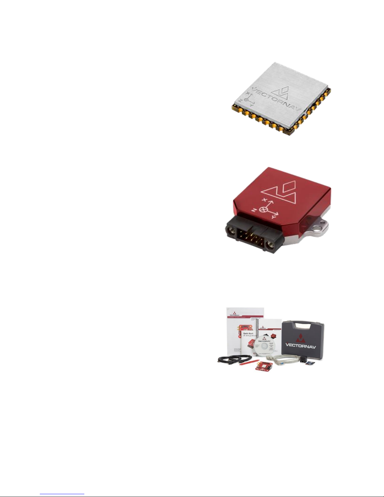
The VN-100 is a miniature surface mount high-performance Inertial Measurement Unit (IMU) and Attitude
Heading Reference System (AHRS). Incorporating the latest solid-state MEMS sensor technology, the VN-
100 combines a set of 3-axis accelerometers, 3-axis gyroscopes, 3-axis magnetometers, a barometric
pressure sensor and a 32-bit processor. The VN-100 is considered both an IMU in that it can output
acceleration, angular rate, and magnetic measurements along the X, Y, & Z axes of the sensor as well as
an AHRS in that it can output filtered attitude estimates of the sensor with respect to a local coordinate
frame.
1.2 Factory Calibration
MEMS inertial sensors are subject to several common sources of error: bias, scale factor, misalignments,
temperature dependencies, and gyro g-sensitivity. All VN-100 sensors undergo a rigorous calibration
process at the VectorNav factory to minimize these error sources. Compensation parameters calculated
during these calibrations are stored on each individual sensor and digitally applied to the real-time
measurements.
Thermal Calibration –this option extends the calibration process over multiple temperatures to
ensure performance specifications are met over the full operating temperature range of -40 C to
+85 C.
1.3 Operation Overview
The VN-100 has a built-in microcontroller that runs a quaternion based Extended Kalman Filter (EKF),
which provides estimates of both the attitude of the sensor as well as the real-time gyro biases. VectorNav
uses a quaternion based attitude filter because it is continuous over a full 360 degree range of motion
such that there are no limitations on the angles it can compute. However, the VN-100 also has a built-in
capability to output yaw, pitch, and roll angles from the VN-100, in which the sensor automatically
converts from quaternions to the desired attitude parameter. Outputs from the VN-100 include:
Attitude:
oYaw, Pitch, & Roll
oQuaternions
oDirection Cosine Matrix
Angular Rates:
oBias-Compensated
oCalibrated X, Y, & Z Gyro Measurements
Acceleration:
oCalibrated X, Y, & Z Measurements
Magnetic:
oCalibrated X, Y, & Z Measurements
Barometric Pressure
The VN-100 EKF relies on comparing measurements from the onboard inertial sensors to two reference
vectors in calculating the attitude estimates: gravity down and magnetic North. Measurements from the

6 UM001
three-axis accelerometer are compared to the expected magnitude and direction of gravity in determining
the pitch and roll angles while measurements from the three-axis magnetometer are compared to the
expected magnitude and direction of Earth’s background magnetic field in determining the heading angle
(i.e. yaw angle with respect to Magnetic North).
The VN-100 Kalman Filter is based on the assumption that the accelerometer measurements should only
be measuring gravity down. If the sensor is subject to dynamic motion that induces accelerations, the
pitch and roll estimates will be subject to increased errors. These measurements can be accounted and
compensated for by using the VN-100 Velocity Aiding Feature (See Section 10 for more information).
The VN-100 filter relies on comparing the onboard magnetic measurements to Earth’s background
magnetic field in determining its heading angle. Common objects such as batteries, electronics, cars,
rebar in concrete, and other ferrous materials can bias and distort the background magnetic field leading
to increased errors. These measurements can be accounted and compensated for by using the VN-100
Hard/Soft Iron Algorithms (See Section 9 for more information).
VectorNav has developed a suite of tools called the Vector Processing Engine (VPE™), which are built-
into the VN-100 and minimize the effects of these disturbances; however, it is not possible to obtain
absolute heading accuracies better than 2 degrees over any extended period of time when relying on
magnetometer measurements.
The VN-100 EKF also integrates measurements from the three-axis gyroscopes to provide faster and
smoother attitude estimates as well as angular rate measurements. Gyroscopes of all kinds are subject
to bias instabilities, in which the zero readings of the gyro will drift over time to due to inherent noise
properties of the gyro itself. The VN-100 EKF uses the accelerometer and magnetometer measurements
to continuously estimate the gyro bias, such that the report angular rates are compensated for this drift.
1.4 Packaging Options
The VN-100 is available in two different configurations; a 30-pin surface mount package (VN-100 SMD)
and an aluminum encased module (VN-100 Rugged). The VN-100 surface mount package is well suited
for customers looking to integrate the VN-100 sensor at the electronics level while the VN-100 Rugged
provides a precision enclosure with mounting tabs and alignment holes for a more off-the-shelf solution.

UM001 7
1.4.1 Surface-Mount Package
For embedded applications, the VN-100 is available in a
miniature surface-mount package.
Features
Small Size: 22 x 24 x 3 mm
Single Power Supply: 3.2 to 5.5 V
Communication Interface: Serial TTL & SPI
Low Power Requirement: < 105 mW @ 3.3V
1.4.2 Rugged Package
The VN-100 Rugged consists of the VN-100 sensor installed
and calibrated in a robust precision aluminum enclosure.
Features
Precision aluminum enclosure
Locking 10-pin connector
Mounting tabs with alignment holes
Compact Size: 36 x 33 x 9 mm
Single Power Supply: 4.5 to 5.5 V
Communication Interface: Serial RS-232 & TTL
1.4.3 Surface Mount Development Kit
The VN-100 Development Kit provides the VN-100
surface-mount sensor installed onto a small PCB,
providing easy access to all of the features and pins on
the VN-100. Communication with the VN-100 is
provided by USB and RS-232 serial communication
ports. A 30-pin header provides easy access to each of
the critical pins. The VN-100 Development Kit also
includes all of the necessary cabling, documentation,
and support software.
Features
Pre-installed VN-100 Sensor
Onboard USB->Serial converter
Onboard TTL->RS-232 converter
30-pin 0.1” header for access to VN-100 pins
Power supply jack –5V (Can be powered from
USB)

8 UM001
Board Size: 76 x 76 x 14 mm
1.4.4 VN-100 Rugged Development Kit
The VN-100 Rugged Development Kit includes the
VN-100 Rugged sensor along with all of the
necessary cabling required for operation. Two
cables are provided in each Development Kit: one
custom cable for RS-232 communication and a
second custom cable with a built in USB converter.
The Development Kit also includes all of the relevant
documentation and support software.
Features
VN-100 Rugged Sensor
10 ft RS-232 cable
10 ft USB connector cable
Cable Connection Tool
CD w/Software Development Kit
User Manual, Quick Start Guide &
Documentation
Carrying Case
1.5 VN-100 Product Codes
VN-100 Options
Item Code
Sensor Packaging
Calibration Option
Product Type
VN-100S
Surface Mount Device
Standard at 25C
IMU/AHRS
VN-100T
Surface Mount Device
Thermal -40C to +85C
IMU/AHRS
VN-100S-DEV
Surface Mount Development Kit
Standard at 25C
IMU/AHRS
VN-100T-DEV
Surface Mount Development Kit
Thermal -40C to +85C
IMU/AHRS
VN-100S-CR
Rugged Module
Standard at 25C
IMU/AHRS
VN-100T-CR
Rugged Module
Thermal -40C to +85C
IMU/AHRS
VN-100S-CR-DEV
Rugged Development Kit
Standard at 25C
IMU/AHRS
VN-100T-CR-DEV
Rugged Development Kit
Thermal -40C to +85C
IMU/AHRS
VN-C100-0310
VN-100 Rugged USB Adapter Cable
N/A
Cable
VN-C100-0410
VN-100 Rugged Serial Adapter Cable
N/A
Cable

UM001 9
2Specifications
2.1 VN-100 Surface-Mount Sensor (SMD) Electrical
Pin assignments (top down view)

10 UM001
VN-100 SMD Pin Assignments
Pin
Pin Name
Type
Description
1
GND
Supply
Ground.
2
GND
Supply
Ground.
3
GND
Supply
Ground.
4
GND
Supply
Ground.
5
TX2
Output
Serial UART #2 data output. (sensor)
6
RX2
Input
Serial UART #2 data input. (sensor)
7
RESTORE
Input
Normally used to zero (tare) the attitude. To tare, pulse high for at least 1 μs.
During power on or device reset, holding this pin high will cause the module to
restore the default factory settings.
As a result, the pin cannot be used for tare until at least 5 ms after a
power on or reset.
Internally held low with 10k resistor.
8
RESV
N/A
Reserved for internal use. Do not connect.
9
SYNC_OUT
Output
Time synchronization output signal.
10
VIN
Supply
3.2 - 5.5 V input.
11
ENABLE
Input
Leave high for normal operation. Pull low to enter sleep mode. Internally pulled
high with pull-up resistor.
12
TX1
Output
Serial UART #1 data output. (sensor)
13
RX1
Input
Serial UART #1 data input. (sensor)
14
RESV
N/A
Reserved for internal use. Do not connect.
15
RESV
N/A
Reserved for internal use. Do not connect.
16
SPI_SCK
Input
SPI clock.
17
SPI_MOSI
Input
SPI input.
18
GND
Supply
Ground.
19
SPI_MISO
Output
SPI output.
20
RESV
N/A
Reserved for internal use. Do not connect.
21
NRST
Input
Microcontroller reset line. Pull low for > 20 μs to reset MCU. Internally pulled
high with 10k.
22
SYNC_IN
Input
Time synchronization input signal.
23
SPI_CS
Input
SPI slave select.
24
RESV
N/A
Reserved for internal use. Do not connect.
25
RESV
N/A
Reserved for internal use. Do not connect.
26
RESV
N/A
Reserved for internal use. Do not connect.
26
RESV
N/A
Reserved for internal use. Do not connect.
28
GND
Supply
Ground.
29
RESV
N/A
Reserved for internal use. Do not connect.
30
GND
Supply
Ground.

UM001 11
2.1.1 VN-100 SMD Power Supply
The minimum operating supply voltage is 3.2V and the absolute maximum is 5.5V.
2.1.2 VN-100 SMD Serial (UART) Interface
The serial interface on the VN-100 operates with 3V TTL logic.
Serial I/O Specifications
Specification
Min
Typical
Max
Input low level voltage
-0.5 V
0.8 V
Input high level voltage
2 V
5.5 V
Output low voltage
0 V
0.4 V
Output high voltage
2.4 V
3.0 V
2.1.3 VN-100 SMD Serial Peripheral Interface (SPI)
Serial I/O Specifications
Specification
Min
Typical
Max
Input low level voltage
-0.5 V
0.8 V
Input high level voltage
2 V
5.5 V
Output low voltage
0 V
0.4 V
Output high voltage
2.4 V
3.0 V
Clock Frequency
8 MHz
16 MHz
Close Rise/Fall Time
8 ns
2.1.4 VN-100 SMD Reset, SyncIn/Out, and Other General I/O Pins
NRST Specifications
Specification
Min
Typical
Max
Input low level voltage
-0.5 V
0.8 V
Input high level voltage
2 V
5.5 V
Weak pull-up equivalent resistor
30 kΩ
40 kΩ
50 kΩ
NRST pulse width
20 μs
SyncIn Specifications
Specification
Min
Typical
Max
Input low level voltage
-0.5 V
0.8 V
Input high level voltage
2 V
5.5 V
Pulse Width
100 ns
SyncOut Specifications
Specification
Min
Typical
Max
Output low voltage
0 V
0.4 V
Output high voltage
2.4 V
3.0 V
Output high to low fall time
125 ns
Output low to high rise time
125 ns
Output Frequency
1 Hz
1 kHz

12 UM001
2.2 VN-100 Rugged Electrical
VN-100 Rugged Pin Assignments
Pin
Pin Name
Description
1
VCC
+4.5V to +5.5V
2
TX1
RS-232 voltage levels data output from the sensor. (Serial UART #1)
3
RX1
RS-232 voltage levels data input to the sensor. (Serial UART #1)
4
SYNC_OUT
Output signal used for synchronization purposes. Software configurable
to pulse when ADC, IMU, or attitude measurements are available.
5
GND
Ground
6
TARE/RESTORE
Input signal used to zero the attitude of the sensor. If high at reset, the
device will restore to factory default state. Internally held low with 10k
resistor.
7
SYNC_IN
Input signal for synchronization purposes. Software configurable to
either synchronize the measurements or the output with an external
device.
8
TX2_TTL
Serial UART #2 data output from the device at TTL voltage level (3V).
9
RX2_TTL
Serial UART #2 data into the device at TTL voltage level (3V).
10
RESV
This pin should be left unconnected.
VN-100 Rugged External Connector

UM001 13
2.2.1 VN-100 Rugged Power Supply
The power supply input for the VN-100 Rugged is 4.5 to 5.5 V DC.
2.2.2 VN-100 Rugged Serial UART Interface
Serial I/O Specifications
Specification
Min
Typical
Max
Input low level voltage
-25 V
Input high level voltage
25 V
Output low voltage
-5.0 V
-5.4 V
Output high voltage
5.0 V
5.5 V
Output resistance
300 Ω
10 MΩ
Data rate
1 Mbps
Pulse slew
300 ns
2.2.3 VN-100 Rugged Reset, SyncIn/Out, and Other General I/O Pins
NRST Specifications
Specification
Min
Typical
Max
Input low level voltage
-0.5 V
0.8 V
Input high level voltage
2 V
5.5 V
Weak pull-up equivalent resistor
30 kΩ
40 kΩ
50 kΩ
NRST pulse width
20 μs
SyncIn Specifications
Specification
Min
Typical
Max
Input low level voltage
-0.5V
0.8V
Input high level voltage
2V
5.5V
Pulse Width
100 ns
SyncOut Specifications
Specification
Min
Typical
Max
Output low voltage
0 V
0.4 V
Output high voltage
2.4 V
3.0 V
Output high to low fall time
125 ns
Output low to high rise time
125 ns
Output Frequency
1 Hz
1 kHz

14 UM001
2.3 VN-100 Surface-Mount Sensor (SMD) Dimensions
* Measurements are in inches
2.4 VN-100 Rugged Dimensions

UM001 15
2.4.1 Rugged Connector Type
The main connector used on the VN-100 Rugged is a 10-pin Harwin M80-5001042. The mating connector
used on the cable assemblies provided by VectorNav for use with the VN-100 Rugged is a Harwin M80-
4861005.
2.5 Absolute Maximum Ratings
SMD Absolute Maximum Ratings
Specification
Min
Max
Input Voltage
-0.3 V
5.5 V
Operating Temperature
-40 C
85 C
Storage Temperature
-40 C
85 C
Rugged Absolute Maximum Ratings
Specification
Min
Max
Input Voltage
-0.3 V
5.5 V
Operating Temperature
-40 C
85 C
Storage Temperature
-40 C
85 C
2.6 Sensor Coordinate System
2.6.1 Sensor Coordinate Frame
The VN-100 uses a right-handed coordinate system. A positive yaw angle is defined as a positive right-
handed rotation around the Z-axis. A positive pitch angle is defined as a positive right-handed rotation
around the Y-axis. A positive roll angle is defined as a positive right-handed rotation around the X-axis.
The axes direction with respect to the VN-100 module is shown in the figure below.
VN-100 Coordinate System

16 UM001
2.6.2 North-East-Down Frame
The VN-100 velocity estimates can be output in the North-East-Down (NED) coordinate frame defined as
follows (NX, NY, NZ):
Right-handed, Cartesian, non-inertial, geodetic frame with origin located at the surface of Earth
(WGS84 ellipsoid);
Positive X-axis points towards North, tangent to WGS84 ellipsoid;
Positive Y-axis points towards East, tangent to WGS84 ellipsoid;
Positive Z-axis points down into the ground completing the right-handed system.

UM001 17
3VN-100 Software Architecture
The software architecture internal to the VN-100 includes four separate subsystems. These subsystems
are the IMU, the NavState, the NavFilter, and the Communication Interface. The high-level functions
performed by these subsystems are outlined below. This chapter describes these functions performed by
these subsystems in more detail and describes which of the various measurement outputs originate from
each of these corresponding subsystems.
VN-100 Software Architecture
3.1 IMU Subsystem
The IMU subsystem runs at the highest system rate, described from this point forward as the IMU Rate
(defaults to 800 Hz). It is responsible for collecting the raw IMU measurements, applying a factory, user,
and dynamic calibration to these measurements, and optionally filtering the individual sensor
measurements for output. The coning and sculling integrals also are calculated by the IMU subsystem at
the full IMU Rate. The IMU subsystem is also responsible for time stamping the IMU measurements to
internal system time, and relative to the SyncIn signal.
IMU
Downsamples
IMU sensors to
800 Hz
Applies Factory
Calibration
Applies User
Calibration
Applies User
Reference
Frame Rotation
Applies User
Low-Pass
Filtering
Applies Onboard
Calibration
Timestamps
Measurements
NavState
Calculates
orientation at
400Hz
Computes delta
angles
Computes delta
velocity
NavFilter
Vector
Processing
Engine
AHRS Kalman
Filter
Hard/Soft Iron
Estimator
World Magnetic
Model
World Gravity
Model
Comm
Interface
Serial ASCII
Serial Binary
SPI
Serial Command
Prompt

18 UM001
3.1.1 Magnetometer
Magnetometer IMU Measurements
3.1.2 Accelerometer
Accelerometer IMU Measurements
3.1.3 Gyro
Gyro IMU Measurements
3.1.4 Raw IMU Measurements
The raw IMU measurements are collected from the internal MEMS at the highest rate available for each
individual sensor. For the gyro and accelerometer, the measurements are down-sampled to the IMU Rate.
3.1.5 Factory Calibration
Each VN-100 sensor is tested at the factory at multiple known angular rates, accelerations, and magnetic
field strengths to determine each sensor’s unique bias, scale factor, axis alignment, and temperature
dependence. The calibration coefficients required to remove these unwanted errors are permanently
stored in flash memory on each sensor. At the IMU Rate, these calibration coefficients are applied to the
raw IMU measurements, to correct for and remove these known measurement errors. For thermally
calibrated units the onboard temperature sensor is used to remove the measurement temperature
dependence. The output of the factory calibration stage is referred to as the calibrated (but un-
compensated) IMU measurements.
Raw
Magnetometer
Data
Factory
Calibration
External
Magnetometer
Data
User
Magnetometer
Compensation
(Register 23)
User Reference
Frame Rotation
(Register 26)
User Low-Pass
Filtering
(Uncompensated)
(Register 85)
Onboard Hard/
Soft Iron
Compensation
(Register 44+47)
Uncompensated
Magnetometer
(uncompMag)
Compensated
Magnetometer
(magBody)
User Low-Pass
Filtering
(Compensated)
(Register 85)
Raw
Accelerometer
Data
Factory
Calibration
User
Accelerometer
Compensation
(Register 25)
User Reference
Frame Rotation
(Register 26)
User Low-Pass
Filtering
(Uncompensated)
(Register 85)
Uncompensated
Accelerometer
(uncompAccel)
Compensated
Accelerometer
(accelBody)
User Low-Pass
Filtering
(Compensated)
(Register 85)
Accelerometer
Filter Bias
Compensation
Raw Gyro Data Factory
Calibration
User Gyro
Compensation
(Register 84)
User Reference
Frame Rotation
(Register 26)
User Low-Pass
Filtering
(Uncompensated)
(Register 85)
Gyro Filter Bias
Compensation
Uncompensated
Angular Rate
(uncompGyro)
Compensated
Angular Rate
(angularRate)
User Low-Pass
Filtering
(Compensated)
(Register 85)

UM001 19
3.1.6 User Calibration
The VN-100 provides the user with the ability to apply a separate user calibration to remove additional
bias, scale factor, and axis misalignments. The user calibration is applied after the factory calibration, and
can be used to optionally fine tune the calibration for each of the individual sensors. The user calibration
is optional and in most cases not required for normal operation.
3.1.7 User Reference Frame Rotation
The user reference frame rotation provides the user with the ability to apply a rigid body rotation to each
of the sensor outputs. This can be used to transform the coordinate system of the onboard sensors into
any other coordinate frame of the user’s choice. Since this transformation is applied to the IMU
measurements prior to their use in the onboard attitude estimation algorithms, applying a user reference
frame rotation will not only change the output coordinates for the IMU measurements, it will also change
the IMU body frame for all subsequent attitude estimation calculations.
A write settings and reset command must be issued after setting the Reference Frame Rotation Register
before coordinate transformation will be applied.
3.1.8 User Low-Pass Filtering
The VN-100 also provides a means (see Register 85) to apply low-pass filtering to the output compensated
IMU measurements. It is important to note that the user low-pass filtering only applies to the output
compensated IMU measurements. All onboard Kalman filters in the NavFilter subsystem always use the
unfiltered IMU measurements after the User Reference Frame Rotation (Register 26) has been applied.
As such the onboard Kalman filtering will not be affected by the user low-pass filter settings. The user
low-pass filtering can be used to down-sample the output IMU measurements to ensure that information
is not lost when the IMU measurements are sampled by the user at a lower rate than the internal IMU
Rate.
3.1.9 Timestamp Measurements
All onboard measurements captured by the IMU subsystem are time stamped relative to several internal
timing events. These events include the monotonically increasing system time (time since startup), the
time since the last SyncIn event, and the time since the last GPS PPS pulse. These timestamps are recorded
with microsecond resolution and ~10 microsecond accuracy relative to the onboard temperature
compensated crystal oscillator. The onboard oscillator has a timing accuracy of ~20ppm over the
temperature range of -40C to 80C.
3.1.10 Coning & Sculling
The IMU subsystem is also responsible for computing and accumulating the coning and sculling integrals.
These integrals track the delta angle and delta velocity accumulated from one time step to another. The
coning and sculling integrals are reset each time the delta angle and/or delta velocity are outputted
(asynchronously) or polled from the delta theta and velocity register (Register 80). Between output and
polling events, the coning and sculling integration are performed by the IMU subsystem at the IMU Rate.

20 UM001
3.2 NavState Subsystem
The NavState subsystem generates a continuous reliable stream of low-latency, low-jitter state outputs
at a rate fixed to the IMU sample rate. The state outputs include any output such as attitude, position,
and velocity, which are not directly measureable by the IMU and hence must be estimated by the onboard
Kalman filters. The NavState runs immediately after, and in sync with the IMU subsystem, at a rate
divisible into the IMU Rate. This rate is referred to as the NavState Rate (default 800 Hz). The NavState
decouples the rate at which the state outputs are made available to the user from the rate at which they
are being estimated by the onboard Kalman filters. This is very important for many applications which
depend on low-latency, low-jitter attitude, position, and velocity measurements as inputs to their control
loops. The NavState guarantees the output of new updated state information at a rate fixed to the IMU
Rate with very low latency and output jitter. The NavState also provides the ability for the VN-100 to
output estimated states at rates faster than the rate of the onboard Kalman filters, which may be affected
by system load and input measurements availability.
3.2.1 NavState Measurements
The measurements shown below are calculated by the NavState subsystem and are made available at the
NavState Rate (default 800 Hz).
NavState Outputs
Attitude
(Yaw, Pitch, Roll, Quaternion, DCM)
Position
(LLA, ECEF)
Velocity
(NED, ECEF, Body)
Delta Angle (Available at full IMU rate)
Delta Velocity (Available at full IMU rate)
3.3 NavFilter Subsystem
The NavFilter subsystem consists of the INS Kalman filter, the Vector Processing Engine (VPE), and its
collection of other Kalman filters and calculations that run at a lower rate than the NavState. Most high
level states such as the estimated attitude, position, and velocity are passed from the NavFilter to the
NavState, and as such are made available to the user at the NavState rate. There are a handful of outputs
however that will only update at the rate of the NavFilter, some of which are listed below.
NavFilter Outputs
Attitude Uncertainty
Position & Velocity Uncertainty
Gyro & Accel Filter Biases
Mag & Accel Disturbance Estimation
Onboard Magnetic Hard & Soft Iron Estimation
World Magnetic & Gravity Model
3.3.1 INS Kalman Filter
The INS Kalman filter consists of an Extended Kalman filter which nominally runs at the NavFilter rate
(default 200 Hz). The INS Kalman filter uses the accelerometer, gyro, GPS, and (at startup) the
magnetometer to simultaneously estimate the full quaternion based attitude solution, the position and
Table of contents
Popular Measuring Instrument manuals by other brands

Triplett
Triplett UTG300 user manual

CENTURION SYSTEMS
CENTURION SYSTEMS G-ULTRA Technical manual

HT
HT VEGA78 user manual

Vaisala
Vaisala RT20A user guide

PCB Piezotronics
PCB Piezotronics IMI SENSORS 646B10 Installation and operating manual

PCB Piezotronics
PCB Piezotronics T356A35 Installation and operating manual

PCB Piezotronics
PCB Piezotronics ICP 356B11/000-06CA Installation and operating manual

Swagelok
Swagelok Fast Loop Module user manual

vinmetrica
vinmetrica SC-50 MLF user manual

PCE Health and Fitness
PCE Health and Fitness PCE-GPA 62 manual

Pentax
Pentax R-2500DN Series instruction manual

YOKOGAWA
YOKOGAWA YS1000 Series user manual