Veetsan VDH63 User manual

DOC. NO. 5956.6K1.00
EDITION: 1 02.2016
CONFORMS TO ANSI/UL Std. 921
CONFORMS TO ANSI/NSF 3
CERTIFIED TO CAN/CSA Std. C22.2 No. 168
VDH63
USA HOOD DISHWASHER
INSTRUCTION MANUAL
Page 3
ES LAVAVAJILLAS CON TAPA
MANUAL DE INSTRUCCIONES PARA EL USO
Pág. 29
FR LAVEUSE À CAPOT
MANUEL D'UTILISATION
Page 57
(*) Original Instructions / Instrucciones originales / Instructions d’origine


The Manufacturer reserves the right to modify the appliances presented in this publication without notice.
El Constructor se reserva el derecho de modificar sin previo aviso, las características de los aparatos presentados en esta publicación.
Le Fabricant se réserve le droit de modifier sans préavis les caractéristiques des appareils présentés dans cette publication.

3
ENGLISH
A GENERAL INFORMATION .............................................................................. Pag. 7
A1 Introduction...................................................................................................................... Pag. 7
A2 Definitions........................................................................................................................ Pag. 7
A3 Typographical conventions .............................................................................................. Pag. 7
A4 Machine and Manufacturer’s identification data............................................................... Pag. 8
A5 Equipment identification .................................................................................................. Pag.8
A5.1 How to identify the technical data........................................................................ Pag. 8
A5.2 How to interpret the factory description............................................................... Pag. 8
A6 Copyright ......................................................................................................................... Pag. 8
A7 Liability............................................................................................................................. Pag. 8
A8 Personal protection equipment ........................................................................................ Pag. 9
A9 Keeping the manual......................................................................................................... Pag. 9
A10 Users of the manual ........................................................................................................ Pag. 9
B GENERAL DESCRIPTION OF MACHINE ....................................................... Pag. 10
B1 General description ......................................................................................................... Pag. 10
C TECHNICAL DATA ........................................................................................... Pag. 10
C1 Main technical characteristics.......................................................................................... Pag. 10
C2 Characteristics of power supply....................................................................................... Pag. 11
D TRANSPORT, HANDLING AND STORAGE.................................................... Pag. 12
D1 Introduction...................................................................................................................... Pag. 12
D1.1 Transport: Instructions for the carrier................................................................... Pag. 12
D2 Handling .......................................................................................................................... Pag. 12
D2.1 Procedures for handling operations..................................................................... Pag. 12
D2.2 Translation ........................................................................................................... Pag. 12
D2.3 Placing the load................................................................................................... Pag. 12
D3 Storage ............................................................................................................................ Pag. 12
E INSTALLATION AND ASSEMBLY................................................................... Pag. 13
E1 Customer responsibilities ................................................................................................ Pag. 13
E2 Characteristics of the place of machine installation......................................................... Pag. 13
E3 Machine space limits ....................................................................................................... Pag. 13
E4 Positioning ....................................................................................................................... Pag. 13
E5 Disposal of packing ......................................................................................................... Pag. 14
E6 Plumbing connections ..................................................................................................... Pag. 14
E6.1 Plumbing circuits ................................................................................................. Pag. 14
E6.2 Installation diagram ............................................................................................. Pag. 15
E7 Electrical connections...................................................................................................... Pag. 16
E8 Energy control arrangement ............................................................................................ Pag. 16
E9 HACCP arrangement....................................................................................................... Pag. 16
EN INDEX

4
F DESCRIPTION OF CONTROL PANEL ............................................................Pag. 17
F1 Basic controls ..................................................................................................................Pag. 17
G STARTING.........................................................................................................Pag. 18
G1 Preliminary checks, adjustments and operational tests...................................................Pag. 18
G1.1 Electrical and plumbing checks ...........................................................................Pag. 18
G1.2 Check the positioning of tank components ..........................................................Pag. 18
G1.2.1 Check the fitting of filters and overflows............................................Pag. 18
G1.2.2 Arm fitting check................................................................................Pag. 18
G2 Starting ............................................................................................................................Pag. 18
G3 Detergent/rinse-aid dispensers and settings ...................................................................Pag. 18
G4 Setting the dispensers .....................................................................................................Pag. 19
H GENERAL SAFETY RULES.............................................................................Pag. 22
H1 Introduction ......................................................................................................................Pag. 22
H1.1 Protection devices installed on the machine........................................................Pag. 22
H1.1.1 Guards ..............................................................................................Pag. 22
H1.2 Safety signs to be displayed on the machine or near the work area ...................Pag. 22
H2 Decommissioning ............................................................................................................Pag. 22
H3 Instructions for use and maintenance..............................................................................Pag. 22
H4 Improper use....................................................................................................................Pag. 23
H5 Residual risks ..................................................................................................................Pag. 23
I NORMAL MACHINE USE.................................................................................Pag. 24
I1 Correct use ......................................................................................................................Pag. 24
I2 Characteristics of personnel enabled to operate on the machine....................................Pag. 24
I3 First use ...........................................................................................................................Pag. 24
I4 Daily activation of machine ..............................................................................................Pag. 24
I5 Wash cycles.....................................................................................................................Pag. 24
I6 Operation .........................................................................................................................Pag. 25
I7 Alarms .............................................................................................................................Pag. 26
I8 Machine cleaning.............................................................................................................Pag. 26
I8.1 End of service and daily internal cleaning ...........................................................Pag. 26
I8.2 Exterior cleaning..................................................................................................Pag. 27
I9 Long idle periods .............................................................................................................Pag. 27
I10 Maintenance ....................................................................................................................Pag. 27
I10.1 Preventive maintenance ......................................................................................Pag. 27
I11 Machine disposal.............................................................................................................Pag. 28
I12 Troubleshooting ...............................................................................................................Pag. 28

ENGLISH
5
INDEX OF FIGURES
Figure 1 Reproduction of the marking/dataplate on the machine .................................................... Pag. 8
Figure 2 Position of marking............................................................................................................. Pag. 8
Figure 3 Technical data identification ............................................................................................... Pag. 8
Figure 4 Example of document identification data. .......................................................................... Pag. 8
Figure 5 Unpacking .......................................................................................................................... Pag. 13
Figure 6 Machine positioning ........................................................................................................... Pag. 13
Figure 7 Removing the film ..............................................................................................................Pag. 13
Figure 8 Feet adjustment ................................................................................................................. Pag. 13
Figure 9 Machine fixing clamp.......................................................................................................... Pag. 14
Figure 10 Feed pipe connection......................................................................................................... Pag. 14
Figure 11 208V 3ph o 240V 3ph ........................................................................................................ Pag. 16
Figure 12 Energy control.................................................................................................................... Pag. 16
Figure 13 HACCP connection position............................................................................................... Pag. 16
Figure 14 Filters and overflow ............................................................................................................ Pag. 18
Figure 15 Wash and rinse arms ......................................................................................................... Pag. 18
Figure 16 Automatic dispenser arrangement ..................................................................................... Pag. 19
Figure 17 Detergent dispenser terminal block.................................................................................... Pag. 19
Figure 18 Rinse aid dispenser terminal block .................................................................................... Pag. 19
Figure 19 YELLOW rack..................................................................................................................... Pag. 25
Figure 20 GREEN rack....................................................................................................................... Pag. 25
Figure 21 BLUE rack for glasses........................................................................................................ Pag. 25
Figure 22 YELLOW container for cutlery............................................................................................ Pag. 25
Figure 23 Filters and overflow ............................................................................................................ Pag. 26
Figure 24 Wash and rinse arms ......................................................................................................... Pag. 27
INDEX OF TABLES
Table 1 Main technical characteristics, performance and consumption.......................................... Pag. 10
Table 2 Control panel...................................................................................................................... Pag. 17
Table 3 Residual risks..................................................................................................................... Pag. 23
EN INDEX OF FIGURES AND TABLES

6
Foreword
The instruction manual (hereinafter Manual) provides the operator with useful information for working correctly and
safely, facilitating him in using the machine (hereinafter “machine”, “dishwasher” or “equipment”).
The following must not be considered a long and exacting list of warnings, but rather a set of instructions suitable for
improving machine performance in every respect and, above all, preventing injury to persons and animals and damage
to property due to improper operating procedures.
All persons involved in machine transport, installation, starting, use and maintenance, repair and dismantling must con-
sult and carefully read this manual before performing the various operations, for the purpose of avoiding wrong and
improper actions that could negatively affect the machine’s integrity or endanger persons.
The manual must always be available to operators and carefully kept in the place where the machine is used so that it is
immediately at hand for consultation in case of doubts or whenever required.
If, after reading this manual, there are still doubts regarding machine use, do not hesitate to contact the Manufacturer, or
the authorized assistance centre, to receive prompt and precise assistance for better operation and maximum efficiency
of the machine.
During all phases of machine use, always respect the current regulations on safety, work hygiene and environmental
protection. It is the user’s responsibility to make sure the machine is started and operated only in optimal safety condi-
tions for persons, animals and property.
To reduce the risk of fire, electrical shock, or injury when using your dishwasher, please follow these basic pre-
cautions including the following:
• Read all instructions before using your dishwasher.
• This Manual does not cover every possible condition and situation that may occur. Use common sense and caution
when installing, operating and maintaining this appliance.
• Do not sit, stand or lean on the hood or racks of a dishwasher.
• Store dishwasher detergent and rinse agents in clearly marked packages with MSDS (Material Safety Data Sheets)
sheets in a safe place.
• FOR YOUR SAFETY DO NOT STORE OR USE GASOLINE OR OTHER FLAMMABLE VAPORS AND LIQUID IN
THE VICINITY OF THIS OR ANY OTHER APPLIANCE.
• Your dishwasher uses hot water to clean and sanitize a variety of wares. Machine surfaces and wares become hot
during and immediately following normal operations. Operators should use caution when loading and unloading
wares from the machine.
• Do not touch the heating element during or immediately after use.
• The installation of this unit must conform to local codes or, in the absence of local codes, to all National Codes gover-
ning plumbing, sanitation, safety and good trade practices.
• This appliance can be used by children aged from 8 years and above and persons with reduced physical, sensory or
mental capabilities or lack of experience and knowledge if they have been given supervision or instruction concerning
use of the appliance in a safe way and understand the hazards involved.
• Do not let children play with the appliance.
• Cleaning and user maintenance shall not be made by children without supervision.
•WARNING: Do not wash the appliance with direct or high pressure jets of water.
• BEFORE SERVICING, DISCONNECT THE ELECTRICAL SERVICE AND PLACE A RED TAG AT THE DISCON-
NECT SWITCH TO INDICATE WORK IS BEING DONE ON THAT CIRCUIT.
•NOTICE: CONTACT YOUR AUTHORIZED SERVICE COMPANY TO PERFORM MAINTENANCE AND REPAIRS.
•NOTICE: Using any parts other than genuine factory manufactured parts relieves the manufacturer of all warranty
and liability.
•NOTICE: Manufacturer reserves the right to change specifications at any time without notice.
•WARNING: The equipment warranty is not valid unless the appliance is installed, started and demonstrated under
the supervision of a factory trained installer.
•WARNING: The unit must be installed by Personnel who are qualified to work with electricity and plumbing. Improper
installation can cause injury to personnel and/or damage to the equipment. The unit must be installed in accordance
with applicable codes.
SAVE THESE INSTRUCTIONS
SAFETY INSTRUCTIONS

ENGLISH
7
AGENERAL INFORMATION
A1 Introduction
This chapter describes the symbols used (that mark and
identify the type of warning) and gives the definitions of
terms used in the manual, responsibilities and copyright.
A2 Definitions
Listed below are the definitions of the main terms used
in the Manual. Carefully read them before using the
Manual.
Operator
an operator who carries out machine installation, adjust-
ment, use, maintenance, cleaning, repair and transport.
Manufacturer
Electrolux Professional S.p.A. or any other assistance
centre authorized by Electrolux Professional S.p.A..
Operator qualified for normal machine use
an operator who has been informed, instructed and
trained regarding the tasks and hazards involved in nor-
mal machine use.
Specialized technician or Technical assistance
an operator instructed/trained by the Manufacturer and
who, based on his professional and specific training,
experience and knowledge of the accident-prevention
regulations, is able to appraise the operations to be car-
ried out on the machine and recognize and prevent pos-
sible risks. His professionalism covers the mechanical,
electrotechnical and electronics fields.
Danger
source of possible injury or harm to health.
Hazardous situation
any situation where an operator is exposed to one or
more hazards.
Risk
a combination of probabilities and risks of injury or harm
to health in a hazardous situation.
Guards
safety measures consisting of the use of specific techni-
cal means (guards and safety devices) for protecting
operators against dangers.
Guard
an element of a machine used specifically to provide
protection by means of a physical barrier.
Safety device
a device (other than a guard) that eliminates or reduces
the risk; it can be used alone or in combination with a
guard.
Customer
the person who purchased the machine and/or who
manages and uses it (e.g. company, entrepreneur, firm).
Emergency stop device
a group of components intended for the emergency stop
function; the device is activated with a single action and
prevents or reduces damage to persons/machines/prop-
erty/animals.
Electrocution
an accidental discharge of electric current on a human
body.
A3 Typographical conventions
For best use of the manual, and therefore the machine, it
is advisable to have good knowledge of the terms and
typographical conventions used in the documentation.
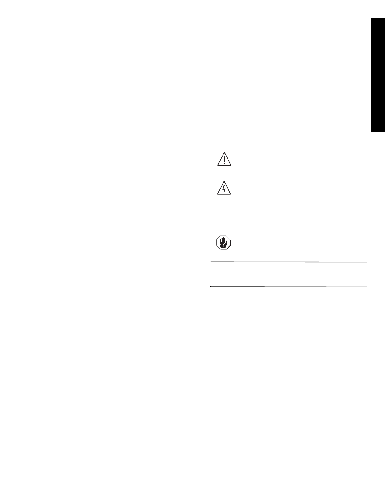
The following symbols are used in the manual to mark
and identify the various types of hazards:
Machine guards and protection devices marked with this
symbol must only be opened by qualified personnel,
after disconnecting the power to the machine.
IMPORTANT
Before servicing, disconnect the electrical main
switches and place a red tag at the disconnect
switch to indicate work is being done on that circuit.
Words and safety warnings further explaining the type of
hazard are placed next to the symbols in the text. The
warnings are intended to guarantee the safety of person-
nel and prevent damage to the machine or the product
being worked.
The drawings and diagrams given in the manual are not
in scale. They supplement the written information with an
outline, but are not intended to be a detailed representa-
tion of the machine supplied.
The numerical values given in the machine installation
diagrams refer to measurements expressed in mm (see
pargraph E6.2 “Installation diagram”).
WARNING!
DANGER FOR THE HEALTH AND SAFETY
OF OPERATORS.
WARNING!
DANGER OF ELECTROCUTION - DAN-
GEROUS VOLTAGE.
WARNING!
DANGER OF DAMAGE TO THE MACHINE.

8
A4
Machine and Manufacturer’s identification data
A reproduction of the marking or dataplate on the
machine is given below.
Figure 1 Reproduction of the marking/dataplate
on the machine
The dataplate gives the product identification and techni-
cal data; the meaning of the information given on it is
listed below.
The marking plate is located on the right side panel of
the equipment.
Figure 2 Position of marking
A5 Equipment identification
A5.1 How to identify the technical data
To identify the technical data (Figure 3) read the factory
description of the product (F.Mod.) on the dataplate,
identify the main machine data and consult the Table 1
“Main technical characteristics, performance and con-
sumption”.
.
Figure 3 Technical data identification
A5.2 How to interpret the factory description
The factory description on the dataplate has the follow-
ing meaning (some examples are given below):
A6 Copyright
This manual is intended for consultation only by the
operator and can be given to third parties only with the
written permission of Electrolux Professional S.p.A..
A7 Liability
The instructions are updated to the month and year
given in the box located at the bottom right of the cover.
The edition corresponds to the manual revision number.
Every new edition replaces and cancels the previous
ones.
Figure 4 Example of document identification data.
The Manufacturer declines any liability for damage and
malfunctioning caused by:
• non-compliance with the instructions contained in this
manual;
• repairs not carried out in a workmanlike fashion, and
replacements using spare parts different from those
F.Mod..................... factory description of the product
Comm. Model........ trade description
PNC....................... production code number
Ser. Nr. ................. serial number
AC 208V 3............. power supply voltage
60 Hz..................... power supply frequency
Max 12.9 kW ......... max. power absorbed
Default 9.9 kW.......
power absorbed as factory setting
2016 ...................... year of construction
IP25....................... protection rating
Electrolux Professional spa - Viale Treviso, 15 -33170
Pordenone (Italy)
..... Manufacturer
2016
F.Mod. VDH63Comm. Model VDH63
PNC 9CGX 504291 00 Ser.Nr. 60610001
EL AC 208V 360 Hz Max 12.9 kW
Default 9.9 kW
Electrolux Professional spa- Viale Treviso, 15 - 33170 Pordenone (Italy)
IP25
2016
F.Mod. VDH63 Comm. Model VDH63
PNC 9CGX 504291 00 Ser.Nr. 60610001
EL AC 208V 3 60 Hz Max 12.9 kW
Default 9.9 kW
Electrolux Professional spa - Viale Treviso, 15 - 33170 Pordenone (Italy)
IP25
Double-skin hood version
(1)(2)(3)(4)
VDH63
Variables description
(1) Mark V = Veetsan Star
(2)..(3) Machine type D = Dishwasher, H = Hood type
(4) Racks/h 63 = capacity 63 racks/h
F.Mod. VDH63
Electrolux Professional spa- Viale Treviso, 15
C1 Main technical characteristics
MODEL VDH63
Power supply Electric
Power supply voltage V 208 3
Frequency Hz 60
DOC. NO. 5956.6K1.00
EDITION: 1 01.2016
Month YearEdition
Number
Document

ENGLISH
9
specified in this manual (the fitting and use of non-
original spare parts and accessories can negatively
affect machine operation);
• operations by non-specialized technicians;
• unauthorized modifications or operations;
• inadequate maintenance;
• improper machine use;
• unexpected extraordinary events;
• use of the machine by uninformed and untrained per-
sonnel;
• non-application of the current provisions in the coun-
try of use, concerning safety, hygiene and health in
the workplace.
The Manufacturer declines any liability for damage
caused by arbitrary modifications and conversions car-
ried out by the user or the Customer.
The employer or workplace manager is responsible for
identifying and choosing adequate and suitable personal
protection equipment to be worn by operators, in compli-
ance with current regulations in the country of use.
Electrolux Professional S.p.A. declines any liability for
possible inaccuracies contained in the manual, if due to
printing or translation errors.
Any supplements to the instruction manual the Customer
receives from the Manufacturer must be kept together
with the manual, of which they will form an integral part.
A8 Personal protection equipment
Give below is a summary table of the Personal Protec-
tion Equipment (PPE) to be used during the various
stages of the machine’s service life.
(1)
Use heat resistant gloves suitable for contact with
water and the substances used (see the safety data
sheet of the substances used to check other possible
PPE).
Failure to use the personal protection equipment by oper-
ators, specialised technicians or users can involve expo-
sure to chemical risk and possible damage to health.
A9 Keeping the manual
The manual must be carefully kept for the entire life of
the machine until decommissioning.
The manual must stay with the machine in case of trans-
fer, sale, hire, granting of use or leasing.
A10 Users of the manual
This manual is intended for:
• the carrier and handling personnel;
• installation and start-up personnel;
• the employer of machine users and the workplace
manager;
• operators in charge of normal machine use;
• specialized technicians - technical assistance (see
wiring diagram and service manual).
Stage
Protective
garments
Safety foot-
wear
Gloves Glasses Safety
helmet
Transport
C
MF
C
F
Handling MMF
CC
Unpacking FMF
CC
Assembly FMF
CC
Normal use MMM(1) F
C
Adjustments FM
CCC
Routine
cleaning FMM(1) F
C
Extraordinary
cleaning
FMM(1) F
C
Maintenance FMF
CC
Dismantling FMF
CC
Scrapping FMF
CC
Key:
MPPE REQUIRED
FPPE AVAILABLE OR TO BE USED IF NECESSARY
C
PPE NOT REQUIRED

10
B GENERAL DESCRIPTION OF MACHINE
B1 General description
The dishwasher is suitable for washing dishes, glasses, cups, cutlery, trays, containers and receptacles in plastic and/or
steel used for preparing, cooking and serving; as well as various cooking utensils in ceramic and/or metal.
The machine is designed for the above-mentioned applications. Under no circumstances may the machine be used for
other applications or ways not provided for in this manual. This equipment has been produced to meet the needs for a
better work environment and economical efficiency. These dishwashers are used in restaurants, cafeterias, cooking cen-
tres and large institutions. The special dish racks, that can be equipped with various inserts, offer practical and easy use
for obtaining excellent washing results. The electronic system enables complete supervision of the washing process.
The control panel also has a display that shows the operating parameters and signals any anomalies.
Systems for scraping and wetting the dishes (e.g. manual prewash spray) and areas for sorting and arranging them in
the racks must be arranged ahead of the dishwasher.
C TECHNICAL DATA
C1 Main technical characteristics
Table 1 Main technical characteristics, performance and consumption
Standard cycle time may vary should the inlet water temperature be different from that indicated above.
MODEL VDH63
Supply voltage: V208 3ph
Frequency Hz 60
Max. power. absorbed kW 12.9 (*)
power absorbed as factory setting
kW 9.9
Boiler heating elements kW 9.0
Tank heating elements kW 3.0
Water supply pressure psi/ kPa 7.25-101/ 50-700
Water supply temperature: °F / °C 50-149 / 10-65
Water supply hardness ppm/ °f 140 / 14 max
Electric conductivity of water
μ
S/in /
μ
S/cm
< 1016 / < 400
Concentration of chlorides in water ppm < 20
Rinse cycle water consumption gal / l 0.53 / 2.0
Boiler capacity gal / l 3.17 / 12
Tank capacity gal / l 6.34 / 24
Cycle duration in ETL-Sanitization mode sec. 57(***)-84-150
Legal noise level Leq dB(A) <63
Minimum Supply - Circuit Ampacity amp 40
Protection rating IP25
Net weight lb [kg]
258 [117]
Shipping weight lb [kg]
284 [129]
Shipping width: inch [mm]
32 1/4” [819]
Shipping height: inch [mm]
68 1/8” [1730]
Shipping depth: inch [mm]
28 13/16” [732]
Power supply cable H07RN-F
Supply cord diameter (min. - max. value) inch [mm]
11/16” [18] - 1” [25]
Latent heat kWh 0.5
Sensible heat kWh 2
(*) = If activated by software, coincidence of tank and boiler heating elements.
(***) = With water supply temperature at 149°F / 65°C.

ENGLISH
11
C2 Characteristics of power supply
The AC power supply to the machine must meet the following conditions:
• max. voltage variation ± 10%
• max. frequency variation ± 1% continuous ± 2% for a short period.
Harmonic distorsion, unbalanced three-phase supply voltage, voltage pulses, interruption, dips and the other electric
characteristics must respect the provisions of point 4.3.2 of Standard EN 60204-1 (IEC 60204-1).
IMPORTANT!
The machine’s power supply must be protected against overcurrents (short circuits and overloads) by
fuses or suitable thermal magnetic circuit breakers. A suitable high-sensitivity manual-reset differen-
tial omnipolar thermal-magnetic switch with contact gap enabling complete disconnection in category
III overvoltage conditions and complying with the current regulations, must be installed between the
power cable and the electric line.
IMPORTANT!
For protection against indirect contacts (depending on the type of supply provided for and connection
of earths to the equipotential protection circuit) refer to point 6.3.3 of EN 60204-1 (IEC 60204-1) with
the use of protection devices that ensure automatic cut-off of the supply in case of isolation fault in
the TN or TT systems or, for IT systems, the use of isolation controllers or differential current protec-
tion devices to activate automatic power disconnection (an isolation controller must be provided for
indicating a possible first earth fault of a live part, unless a protection device is supplied for switching
off the power in case of a such a fault. This device must activate an acoustic and/or visual signal
which must continue for the entire duration of the fault).
For example: in a TT system, a differential switch with cut-in current (e.g. 30 mA) coordinated with the
earthing system of the building where the machine is located must be installed ahead of the supply.
IMPORTANT!
Customers are requested to follow these instructions, otherwise the Manufacturer does not guarantee
the machine for continuous operation and/or against faults.

12
D TRANSPORT, HANDLING AND STORAGE
D1 Introduction
Transport (i.e. transfer of the machine from one place to
another) and handling (i.e. transfer inside workplaces)
must occur with the use of special equipment of ade-
quate capacity.
The machine must only be transported, handled and
stored by qualified personnel, who must have:
- specific technical training and experience;
- knowledge of the safety regulations and applicable
laws in the relevant sectors;
- knowledge of the general safety provisions;
- the ability to recognize and avoid any possible haz-
ard.
D1.1 Transport: Instructions for the carrier
D2 Handling
Arrange a suitable area with flat floor for machine
unloading and storage operations.
D2.1 Procedures for handling operations
For correct and safe lifting operations:
• use the type of equipment most suitable for charac-
teristics and capacity (e.g. lift trucks or electric pallet
truck);
• cover sharp edges;
• check the forks and lifting procedures according to
the instructions given on the packing.
Before lifting:
• send all operators to a safe position and prevent per-
sons from accessing the handling zone;
• make sure the load is stable;
• make sure no material can fall during lifting, and
manoeuvre vertically in order to avoid impacts;
• handle the machine, keeping it at minimum height
from the ground.
D2.2 Translation
The operator must:
• have a general view of the path to be followed;
• stop the manoeuvre in case of hazardous situations.
D2.3 Placing the load
Before placing the load make sure the path is free and
that the floor is flat and can take the load.
D3 Storage
The machine and/or its parts must be stored and pro-
tected against damp, in a non-aggressive place free of
vibrations and with room temperature of between -
10°C / 14°F and 50°C / 122°F.
The place where the machine is stored must have a flat
support surface in order to avoid any twisting of the
machine or damage to the support feet.
WARNING!
Do not stand under suspended loads
during the loading/unloading phases.
Unauthorized personnel must not access
the work zone.
IMPORTANT!
The machine’s weight alone is not suffi-
cient to keep it steady.
The transported load can shift:
- when braking;
- when accelerating;
- in corners;
- on particularly rough roads.
CAUTION!
For machine lifting, do not use movable
or weak parts such as casings, electrical
raceways, pneumatic parts, etc., as
anchoring points.
IMPORTANT!
Machine positioning, installation and dis-
assembly must be carried out by a spe-
cialized technician.
IMPORTANT!
Do not make modifications to the parts
supplied with the machine. Any missing
or faulty parts must be replaced with
original parts.

ENGLISH
13
E INSTALLATION AND ASSEMBLY
IMPORTANT
Before servicing, disconnect the electrical main
switches and place a red tag at the disconnect
switch to indicate work is being done on that circuit.
E1 Customer responsibilities
The Customer must provide for the following:
- Install a disconnecting switch with a capacity at least
equal to that given in the technical data table, a 30mA
residual current circuit breaker and an overcurrent
device (magnetothermal cut-out with manual reset or
fuse) between the appliance and the mains power
outlet. The chosen device must be lockable in the
open position in case of maintenance.
- install an adequate electrical power supply ahead of
the machine, according to the equipment’s technical
specifications (Table 1 and C2 “Characteristics of
power supply”);
- the equipotential connection of the workplace electri-
cal system to the metal structure of the machine by
means of a copper cable of adequate section (see
position “EQ” in par. E6.2 “Installation diagram”);
- Adducting for the electrical connection between the
workplace electric panel and the equipment;
- the water supply and drain connections and other
connections as indicated in Table 1 and par. E6
“Plumbing connections”;
E2 Characteristics of the place of machine
installation
The machine is designed for installation in professional
and not domestic-type kitchens. Water collection traps/
metal grates must be arranged in the floor at the
machine discharges (see pargraph E6.2 “Installation dia-
gram”), possibly replaceable with a single water trap
sized for a flow rate of at least 0.79 gal/s (3 l/s).
E3 Machine space limits
A suitable space must be left around the machine (for
operations, maintenance, etc.). The passages enabling
personnel to operate on the machine must be at least 19
11/16” (50 cm) wide, except at the rear of the machine.
The size must be increased in case of use and/or trans-
fer of other equipment and/or means or if exit routes are
necessary inside the workplace.
E4 Positioning
The machine must be taken to the place of installation
and the packing base removed only when being
installed.
Arranging the machine:
•Wear protective gloves and unpack the machine
(Figure 5).
Figure 5 Unpacking
• Lift the appliance using a lift truck, remove the base
and position the appliance where it is to be installed
(Figure 6).
• Carefully remove the protective film from the outer
panels without tearing it, to avoid leaving traces of
glue (Figure 7).
• Adjust the equipment by turning the special adjusta-
ble feet and making sure it is perfectly level, both
lengthwise and crosswise (Figure 8).
Figure 8 Feet adjustment
IMPORTANT!
Machine installation operations must only
be carried out by specialized Technicians
provided with all the appropriate personal
protection equipment (safety shoes,
gloves, glasses, overalls, etc.), tools, uten-
sils and ancillary means.
Figure 6 Machine
positioning
Figure 7 Removing
the film

14
•The appliance must be fixed to the floor using the two
clamps supplied (Figure 9).
Figure 9 Machine fixing clamp
• Accessing the appliance bottom panel.
• Fit the clamps on feet as shown in supplied technical
sheet.
•
Screw the appliance steadily to the floor using hole
clamps
.
E5 Disposal of packing
All materials used for packing are environmentally com-
patible. They can be safely kept, and recycled or burnt in
a special waste incineration plant. Plastic parts subject
to possible recycling are marked as follows:
Parts in wood and cardboard can be disposed of
respecting the current regulations in the country of use.
E6 Plumbing connections
IMPORTANT
Watermark labelled machines must be installed in
accordance with AS/NZS 3500.1.
Install the machine water filling and drain pipes according to
the plumbing circuit and installation diagrams given below.
•Connect the appliance water supply pipe “WI” (see
paragraph E6.2 Installation diagram) to the mains, fit-
ting a cut-off valve, the filter provided and a pressure
gauge between the appliance and the mains
(Figure 10).
Figure 10 Feed pipe connection
•Check that the dynamic water supply pressure,
measured between the appliance and the main, is
between 7.25 and 101 psi (50 and 700 kPa) (test
while dishwasher tank or boiler is filling with water).
If the pressure is too high, fit a suitable pressure
reducer on the inlet pipe.
•Connect the waste outlet pipe “D” (see pargraph E6.2
Installation diagram) to the main drain pipe, fitting a trap,
or place the outlet pipe over an S trap set into the floor.
E6.1 Plumbing circuits
polyethylene: outer wrapping, instruc-
tion booklet bag.
polypropylene: roof packing panels,
straps.
polystyrene foam: corner protectors.
PE
PP
PS
!
IMPORTANT!
Always use a new set of joints if you
remove and reinstall the water inlet pipe
to the appliance.
Plumbing circuit diagram
LEGEND
WI = Water inlet
M1 = Wash pump
M3 = Rinse pump
AG = Air Gap
YV1 = Filling solenoid valve

ENGLISH
15
E6.2 Installation diagram
The following installation diagrams give the machine overall dimensions and position of water and electrical connections.
IMPORTANT!
Make sure to install an extractor hood to remove the steam produced by the machine.
The hood air flow must be calculated taking into account the type of installation and the work environ-
ment where it is installed. In any case, an air flow rate of between 590 cfm (1000 m3/h) and 885 cfm
(1500 m3/h) is recommended.
LEGEND
WI Water inlet
DDrain outlet
EI Power supply entry
EQ Equipotential screw
XD Pipe inlet for detergent
XR Pipe inlet for rinse aid
XI Pipe inlet for de-lime

16
E7 Electrical connections
Connection to the power supply must be carried out in
conformity with the current regulations and provisions in
the country of use.
• Make sure the machine power supply voltage speci-
fied on the rating plate (Table 1) matches the mains
voltage.
• Make sure the system power supply is arranged and
able to take the actual current load and that it is exe-
cuted in a workmanlike manner according to the reg-
ulations in force in the country of use.
• The earth wire at the terminal end must be longer
(max. 3/4” [20 mm]) than the phase wires.
• Connect the earth wire of the power supply cable to
an efficient earth clamp. The appliance must also be
included in a unipotential system, the connection
being made through the screw “EQ” (see pargraph
E6.2 Installation diagram) marked with the symbol
“”. The unipotential wire must have a cross section
of 10 mm2.
Power supply 208V 3ph or 240V 3ph
Figure 11 208V 3ph o 240V 3ph
Open the power supply terminal board and insert the jum-
pers provided as follows: one jumper between terminals 1
and 2, one between terminals 3 and 4 and another between
terminals 5 and 6. Using a suitable power supply cable (see
technical data table), connect the three phases to terminals
1, 3 and 5 and the earth wire to the terminal .
E8 Energy control arrangement
The machine is arranged for external control of energy
consumption.
Figure 12 Energy control
Connect the energy peak controller across terminals 11
and 12 (Figure 12).
Safety devices
• An automatic reset thermoamperometric protective
device incorporated in the windings of the electric
pump cuts off the electricity supply in the case of mal-
functioning.
• In the event of water mains failure, a device prevents
water in the boiler from returning into the mains.
• An overflow pipe, connected to the drainage outlet,
maintains the water in the tank at a constant level.
Failure to comply with safety rules and regulations
relieves the manufacturer of all liability.
E9 HACCP arrangement
The machine is arranged for the HACCP connection it is
still necessary to order the network connection cable.
Connect the HACCP network to terminals 2 and 3 of
connector X4.
Figure 13 HACCP connection position
IMPORTANT!
Work on the electrical systems must only
be carried out by a qualified electrician.
L1
L2
L3
11
12
CAUTION
A normally open (n.o.) contact of the con-
troller must be connected across termi-
nals 11 and 12. When this contact closes
the boiler heating elements are discon-
nected. Using the dishwasher in these
conditions may increase the cycle time.
IMPORTANT!
If the power cable is damaged it must be
replaced by the After-Sales Service or in
any case by qualified personnel, in order
prevent any risk.
!

ENGLISH
17
F DESCRIPTION OF CONTROL PANEL
Table 2 Control panel
Described below are all the single keys and functions present in the various control panel models listed above. Some
functions are shared by all models of the range, whereas others are available only on several versions.
F1 Basic controls
On/Off
This key indicates the status of the equipment: on or off.
When the appliance is on, the key is lit.
Wash cycle 1
This button starts wash cycle 1. This cycle is recommen-
ded for washing not very dirty dishes.
Wash cycle 2
This button starts wash cycle 2. This cycle is recommen-
ded for washing very dirty dishes.
Drain / self-cleaning cycle
This button starts a drain / self-cleaning cycle.
Delime cycle (only be activated by a specialised
technician)
This button is used to run a machine water circuit delime
cycle.
A
D
F
L
H
B
E
I
G
C
Legend
A= On / Off
B= “Tank temperature” indicator light
C= “Water tap” indicator light
D= “Boiler temperature” indicator light
E= Wash cycle 1
F= Wash cycle 2
G= Parameter button 1
H= Parameter button 2
I= Drain / self-cleaning cycle
L= Delime cycle (this function can only be activated by a specialised
technician)
The temperature shown on the display is that of the tank if the light “B” is
on, or of the boiler if the indicator light “D” is on. The tank temperature is
displayed during the wash cycle and the boiler temperature during the
rinse cycle.

18
GSTARTING
G1 Preliminary checks, adjustments and
operational tests
G1.1 Electrical and plumbing checks
Before starting the machine:
• check correct connection of the electrical wires that
feed the machine;
• make sure the power supply voltage and frequency
match the data given in Table 1;
• check correct connection of the water supply and
drain pipes (see par. E6 “Plumbing connections”);
• make sure all the guards and safety devices are in
place and efficient.
G1.2 Check the positioning of tank components
G1.2.1 Check the fitting of filters and overflows
Make sure the filter "1", the overflow "2" and the flat filter
"3" are correctly fitted (Figure 14).
.
G1.2.2 Arm fitting check
Make sure the upper and lower wash and rinse arms are
correctly fitted (Figure 15).
G2 Starting
• Open the water supply valves.
• Turn the main switch of the machine to “I”.
• Press the On/Off key Table 2 (“A” - “Control panel”).
G3 Detergent/rinse-aid dispensers and settings
If the appliance is connected to a water softener or
osmotic device, contact the detergent supplier for a spe-
cific product.
If the peristaltic dispensers are installed in the machine,
the detergent/ rinse aid dosage is made automatically
according to the desired concentration.
The detergent / rinse aid concentration depends on the
product type and the water supply hardness (check the
features on the product label).
IMPORTANT
The peristaltic dispensers (detergent and rinse aid)
and the tube inside the rinse aid dispenser require
periodical maintenance (at least once or twice a year)
or after prolonged periods of machine inactivity.
1. Dishwasher with incorporated detergent dis-
penser (Figure 16).
When the appliance is filled with water for the first time in
the day, pump “R” dispenses a detergent quantity in the
tank providing a concentration of 0.017 lb/gal (2 g/l). In
order to change this value, access the parameter
(see
G4 Setting the dispensers)
.
At each cycle, pump “R” dispenses a detergent quantity
in the tank providing a concentration of 0.017 lb/gal (2 g/
l). In order to change this value, access the parameter
(see
G4 Setting the dispensers)
.
Insert the supplied hose into the detergent container.
IMPORTANT!
These operations must only be carried
out by specialized technicians provided
with adequate personal protection equip-
ment (e.g. safety footwear, gloves,
glasses, etc.), tools and suitable ancillary
equipment.
IMPORTANT!
The following operations must be carried
out by operators provided with suitable
personal protection equipment (e.g. pro-
tective gloves, etc.) with the machine
switched off and cold.
Figure 14 Filters and overflow
3
2
1
Figure 15 Wash and rinse arms
Table of contents
Languages:
Other Veetsan Dishwasher manuals
Popular Dishwasher manuals by other brands

GE
GE GSC3500 owner's manual

Maytag
Maytag MDB6759AWW - 24 Inch Fully Integrated... installation instructions

Fisher & Paykel
Fisher & Paykel DishDrawer DD60SCHX9 operating instructions

Electrolux
Electrolux U26220 Installation and operating instructions

Amica
Amica GSP 530 910 SI operating instructions

Samsung
Samsung DMT800RHW user manual