8
A fused disconnect switch or a main circuit breaker
(customer furnished) MUST be installed in the
electric supply line for the appliance. It is recom-
mended that this switch/circuit breaker have
lockout/tagout capability. Before making any electri-
cal connections to this appliance, check that the
power supply is adequate for the voltage, amperage,
and phase requirements on the rating plate.
The chosen device must be lockable in the open
position in case of maintenance.
RATING PLATE
The rating plate contains identification and technical
data and is located on the right-hand side panel of the
appliance (Figure 5).
Figure 5
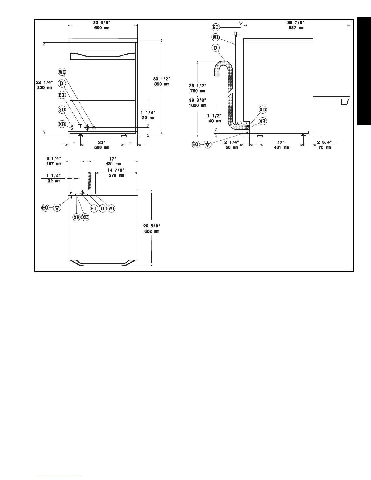
C1 WATER CONNECTION
• Position the dishwasher and level the appliance by
adjusting the appropriate bullet feet (Figure 5).
• Connect the appliance water supply pipe “A”
(Figure 4) (keeping with local plumbing codes) to the
incoming water supply. Install a shutoff valve, Y-
Strainer, and a pressure gauge between the appli-
ance and the incoming water supply of the unit
(Figure 6).
• In models with incorporated water softener, connect
the double non-return valve "B" (Figure 6) supplied
and the machine supply pipe.
Figure 6
•Check that the dynamic water supply pressure measures
between 7.25 - 101 psi/50 - 700kPa while dishwasher
tank or boiler is filling with water.
If the pressure is too high, install a suitable pressure
regulator on the incoming water supply to the unit.
Position the outlet pipe at a height anywhere between 29
1/2” to 39 3/8”/750 to 1000mm from the floor.
Check that about 0.8 gallon/3 litres of water flow out of
the outlet pipe during the rinse cycle.
Make sure drain hose does not kink, pinch or twist,
resulting in a water flow restriction.
C2 ELECTRICAL CONNECTION
Figure 7
The installation of this unit must conform to local
codes or, in the absence of local codes, to all Natio-
nal Codes governing plumbing, sanitation, safety
and good trade practices.
• Check the over rating plate before making any
electric supply connections. Electric supply con-
nections must agree with data on the unit rating plate.
• The earth wire at the terminal end must be
3/4”/20mm (max.) longer than the phase wires.
• The appliance requires a ground connection to the
unit ground screw located at the rear of the unit mar-
ked “Q” (Figure 4) in the manual and marked with the
symbol “ “ on the unit. The ground wire must have a
cross section of AWG 8/8.35 mm2. Do not use the
wiring conduit or other piping for ground connections.
If necessary, have the electrician supply the ground
wire.
C INSTALLATION AND START-UP INSTRUCTIONS
2016
F.Mod. VDU30 Comm. Model VDU30
PNC 9CGX 502350 00 Ser.Nr.60110001
EL AC 208V / 1 60 Hz Max 8.85 kW
(AC 208 V / 3)
Nominal 6.85 kW
Min
Electrolux Professional spa - Viale Treviso, 15 - 33170 Pordenone (Italy)
IPX4
CAUTION
THE ELECTRICAL CONNECTIONS MUST
MEET ALL NATIONAL AND ELECTRICAL
CODE REQUIREMENTS.
AC 400....
1
11
10
9
8
7
6
5
4
3
2
12