DOC. NO. 5956.6K6.00 P. 2 / 28
INDEX
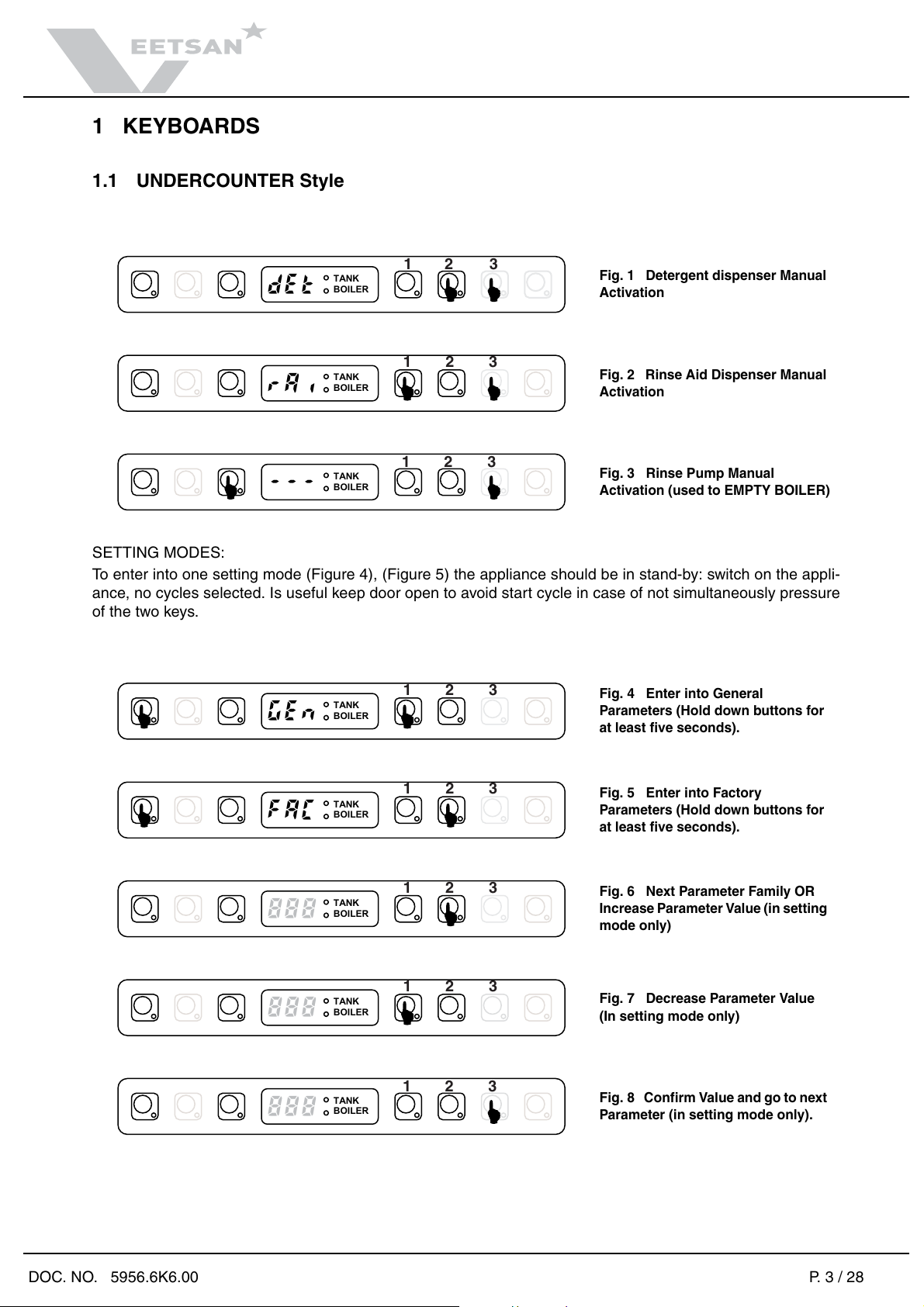
1 KEYBOARDS Pag. 3
1.1 UNDERCOUNTER Style Pag. 3
1.1 UNDERCOUNTER Style Pag. 3
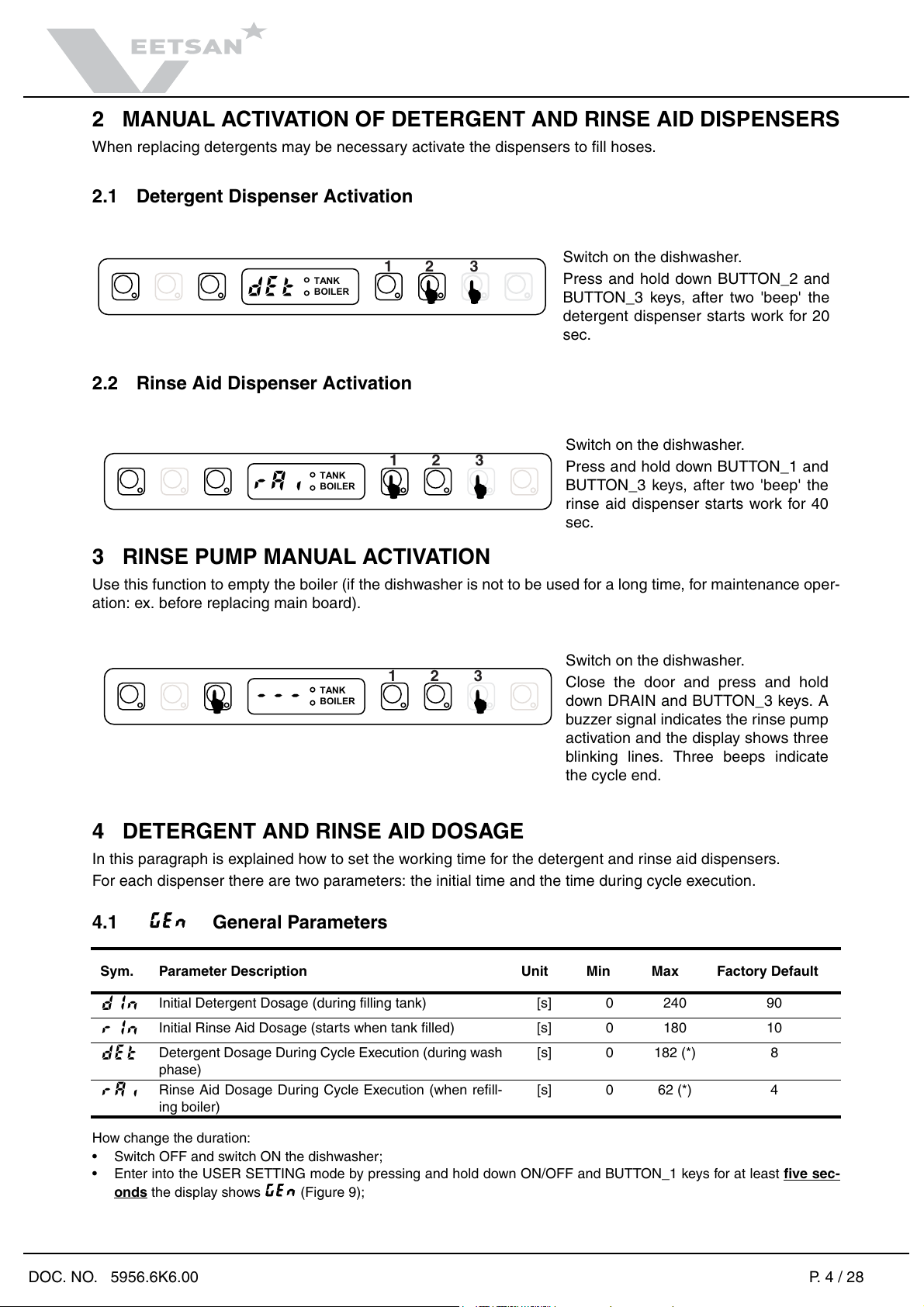
2 MANUAL ACTIVATION OF DETERGENT AND RINSE AID DISPENSERS Pag. 4
2.1 Detergent Dispenser Activation Pag. 4
2.2 Rinse Aid Dispenser Activation Pag. 4
3 RINSE PUMP MANUAL ACTIVATION Pag. 4
4 DETERGENT AND RINSE AID DOSAGE Pag. 4
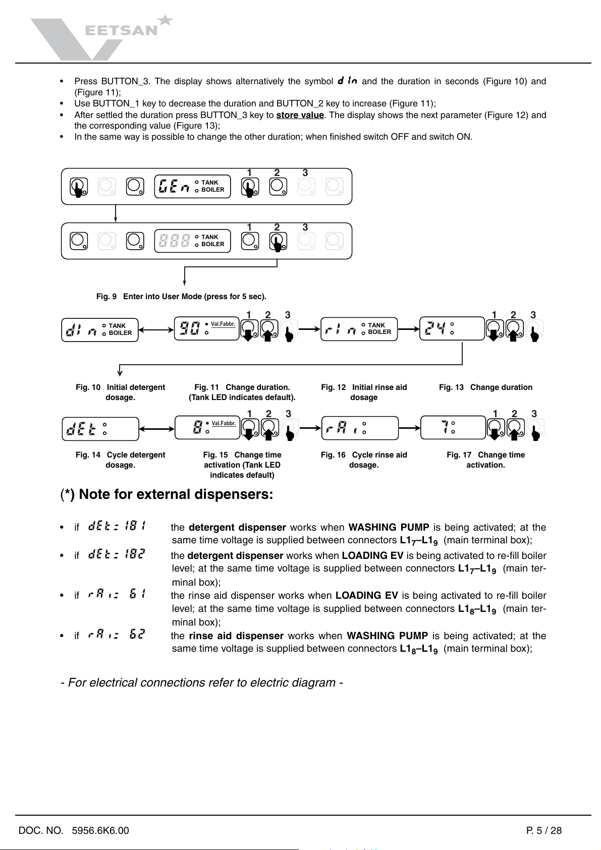
4.1 GEn General Parameters Pag. 4
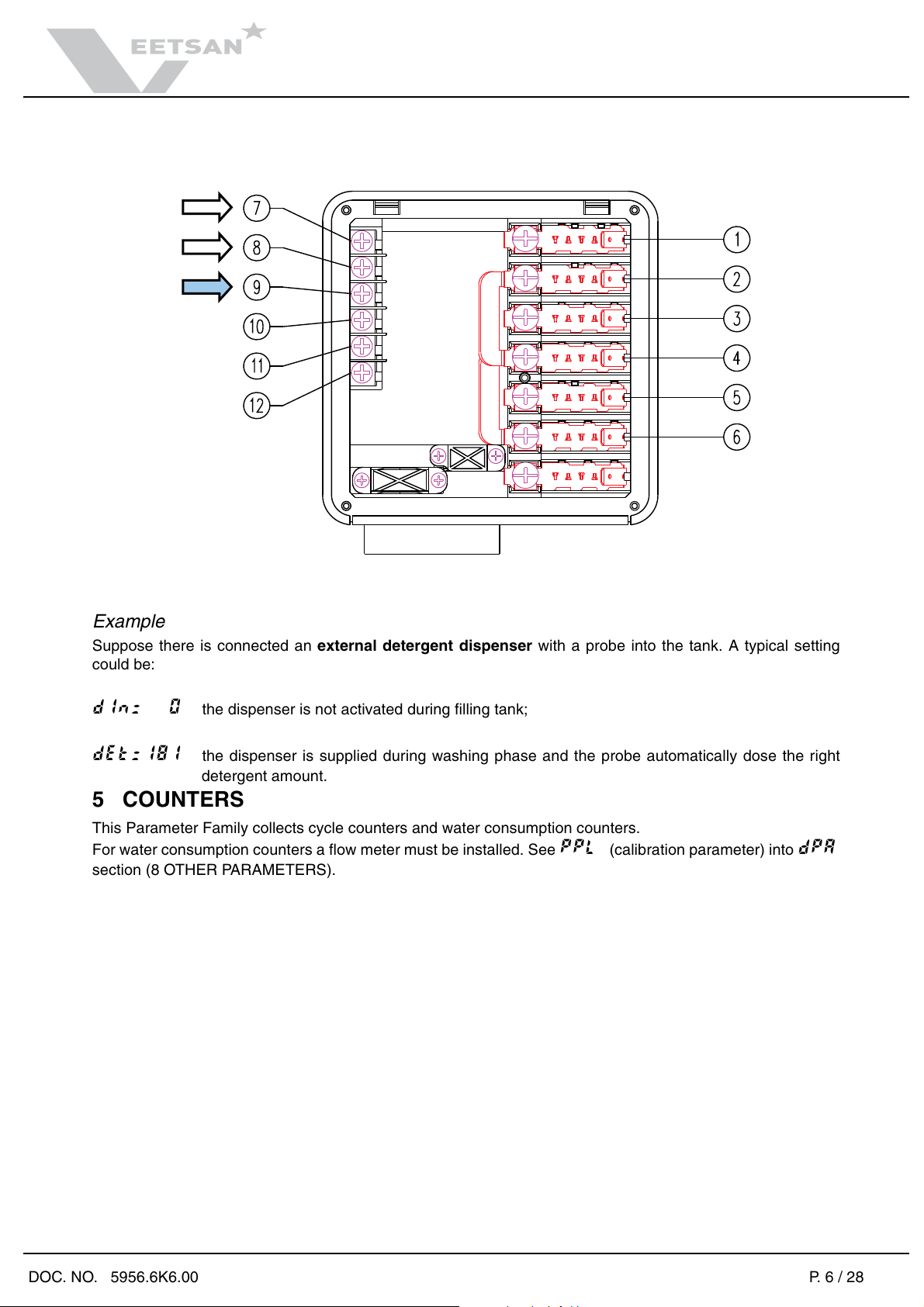
5COUNTERS Pag. 6
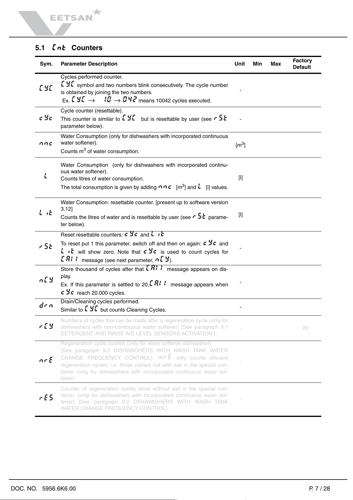
5.1 Cnt Counters Pag. 7
6 TEMPERATURE SETTING Pag. 8
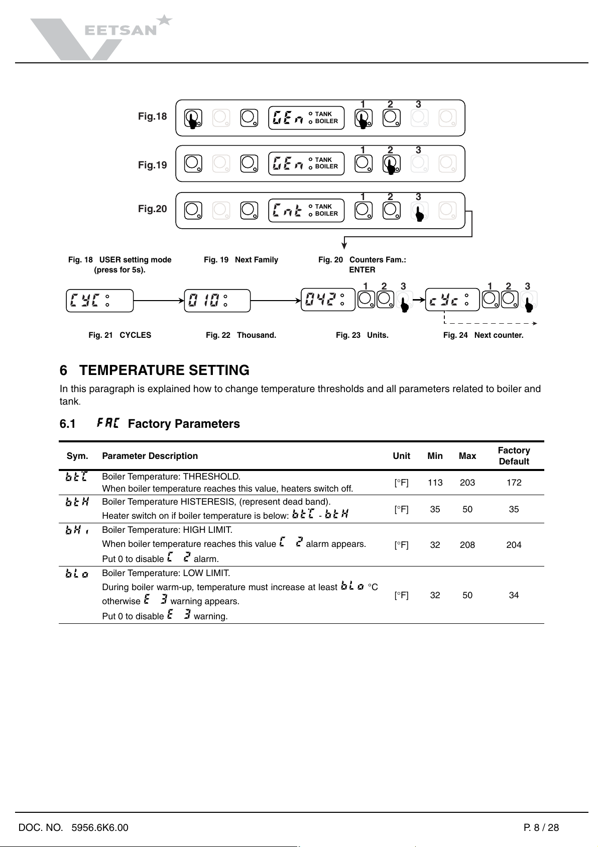
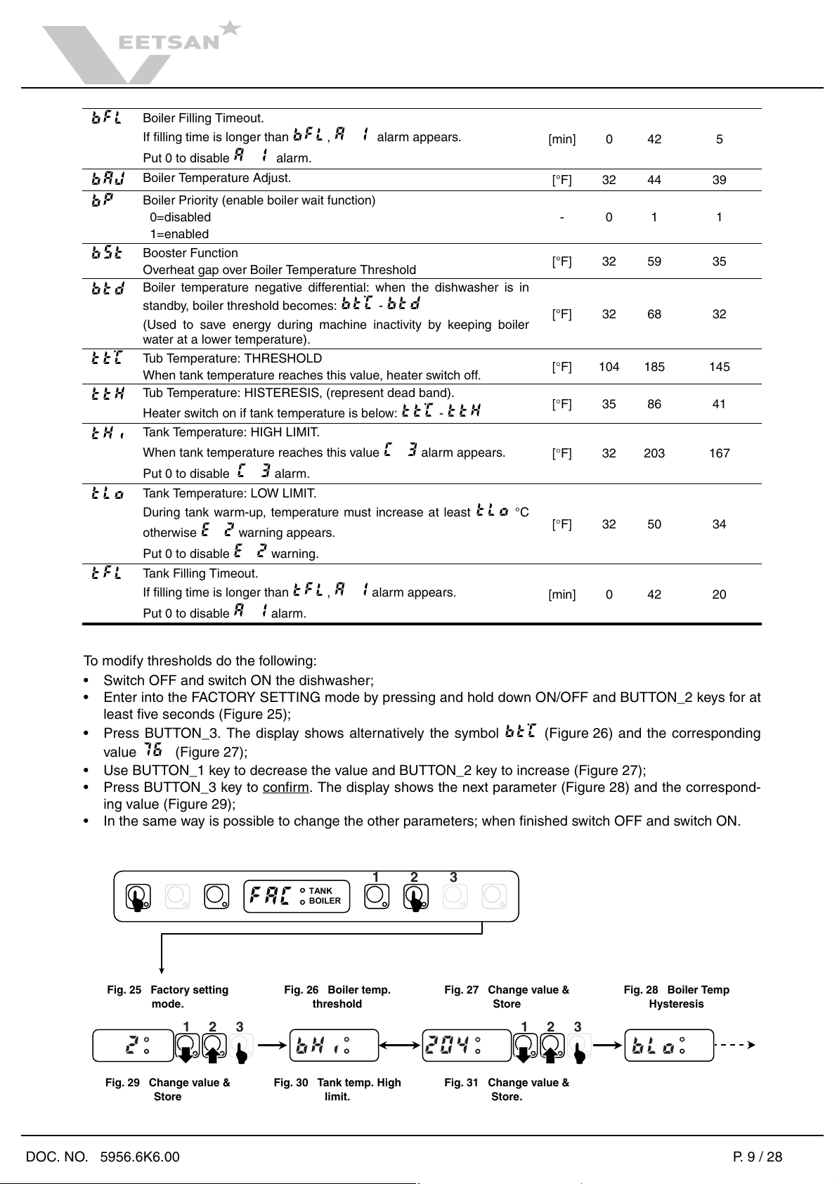
6.1 FAC Factory Parameters Pag. 8
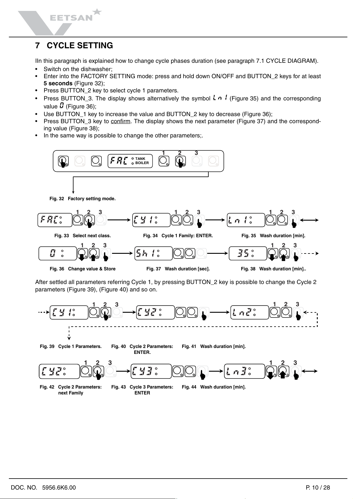
7 CYCLE SETTING Pag. 10
7.1 CYCLE DIAGRAM Pag. 11
7.2 CY1 Cycle 1 Parameters Pag. 12
7.3 CY2 Cycle 2 Parameters Pag. 12
7.4 drn Drain/Cleaning Cycle Parameters Pag. 12
7.4 drn Drain/Cleaning Cycle Parameters Pag. 12
8 OTHER PARAMETERS Pag. 13
8.1 dPA Dishwashing Parameters Pag. 13
8.2 ron Read Only Parameters Pag. 14
8.3 HCP Communication and HACCP Parameters Pag. 14
8.4 CFG Configuration Parameters Pag. 15
8.5 dbG Parameters for automatic hood type dishwashers Pag. 16
9 SPECIAL FEATURES Pag. 17
9.1 DETERGENT AND RINSE AID LEVEL SENSORS ACTIVATION Pag. 17
9.1 DETERGENT AND RINSE AID LEVEL SENSORS ACTIVATION Pag. 17
9.1 DETERGENT AND RINSE AID LEVEL SENSORS ACTIVATION Pag. 17
9.2 DISHWASHERS WITH WASH TANK WATER CHANGE FREQUENCY CONTROL Pag. 17
9.2 DISHWASHERS WITH WASH TANK WATER CHANGE FREQUENCY CONTROL Pag. 17
9.2 DISHWASHERS WITH WASH TANK WATER CHANGE FREQUENCY CONTROL Pag. 17
9.3 PERISTALTIC TUBE FITTING AND REPLACEMENT INSTRUCTIONS Pag. 17
10 MAIN BOARD CONFIGURATION Pag. 20
10.1 CODE -> Prog. TABLE Pag. 20
10.2 PROGRAMMING SHEETS Pag. 21
11 DEFAULT VALUES Pag. 22
12 USER INTERFACE AND MAIN BOARD CONNECTORS Pag. 23
12.1 Main malfunctions not due to the main board Pag. 23
12.2 CONNECTORS LAYOUT Pag. 23
14 ALARM MESSAGES AND TROUBLESHOOTING Pag. 24
14.1 ALARMS THAT STOP THE DISHWASHER Pag. 24
14.2 ALARMS THAT DON'T STOP THE DISHWASHER Pag. 25
In the case of a shorted probe error (C 5, C 7 e C11), the displayed temperature
is 210°F. Pag. 26
15 LIST OF PARAMETERS FOR SUBSEQUENT VERSIONS Pag. 27