Vega Industries VLB-5X User manual

VLB-5X LED Beacon
AIS-Compatible
Installation and Operation Manual
STAND ALONE & SELF CONTAINED
•Marine Beacon
•Bridge Light
•Aircraft Hazard Light
VLB-5X Product Manual
Available colour range Red, Green, White, Yellow or Blue
Available models
SA-Stand Alone (No Solar panels)
SS-Standard Solar 8W with 12Ah battery
LS1-Large Solar 16W with 12Ah Battery
LS2-Large Solar 16W with 24Ah Battery
Vertical divergence 7° Marine Beacon, Obstacle Light and
Wreck Light
Options
Internal GPS for synchronising
RS232 Data port (RS485 optional)
Sync and monitor wire
AIS-compatible
Product Version 1.00
Software version: 8.11
Manual version: 1.2
Date released: Aug 2017
V E G A I N D U S T R I E S L I M I T E D
VLB-5X-SA-Stand Alone VLB-5X-SS-Standard Solar VLB-5X-LS-Large Solar

Instruction Manual VLB-5X LED Beacon © Vega Industries Ltd, Aug 2017
VLB-5X LED Beacon Page 2 of 53 VLB-5X V1.2
Manual revision history
Serial Communications Protocol Compatibility
VLB5X beacons with software versions lower than 811 (or 722 for Lead-Acid Battery variants) may not communicate correctly over the
serial interface with a Vega AIS device. Please contact Vega Industries to arrange a software update.
Manual Version
Released Description of Change Software version
VLB-5X Serial number
1.0.0 Dec 2016 •First issue. 800 67-00050000
1.1 Jul 2017 •Added CSQ query command 810 67-00050000+
1.2 Aug 2017 •Add coms protocol compatibility section 811 67-00050964+

Instruction Manual VLB-5X LED Beacon © Vega Industries Ltd, Aug 2017
VLB-5X LED Beacon Page 3 of 53 VLB-5X V1.2
VLB-5X LED Versions by colour, release date and serial number
RED LED
GREEN LED
LED Version
Release Date
VLB
-
5X
Serial Number
LED Version
Release Date
VLB
-
5X
Serial Number
Vega 116 Dec 2009 Vega 223 Dec 2009
Vega 163 Aug 2011 67-50000 Vega 263 Aug 2011 67-50000
WHITE LED
YELLOW LED
LED Version
Release Date
VLB
-
5X
Serial Number
LED Version
Release Date
VLB
-
5
X
Serial Number
Vega 422 Dec 2009 Vega 320 Dec 2009 67-50000
Vega 423 May 2011
Vega 463 July 2013 67-50000
BLUE LED
LED Version
Release Date
VLB
-
5X
Serial Number
Vega 525 Dec 2009 67-50000
VEGA INDUSTRIES LIMITED
21 Heriot Drive, Porirua 5022, New Zealand
Tel: +64 4 238 0200; Fax: +64 4 237 4392
E-mail: sales@vega.co.nz Web: http://www.vega-navigation.com
Product Warranty
Vega warrants that all products supplied are free from labour and material defects, and will repair or replace (at its
option) the whole or any part of the products found to be faulty. Vega is not liable for any charge beyond the point of
delivery, including installation, alignment or testing. To claim under warranty the product must be returned to the
manufacturer.
To view Vega’s warranty terms and conditions please visit http://www.vega.co.nz/terms-and-conditions/.
Legal Notice
Information in this document is subject to change without notice. Vega Industries Ltd. makes no warranty of any kind with regards to
this material, including but not limited to, the implied warranties of merchantability and fitness for purpose. Vega Industries Ltd. shall not
be liable for errors contained herein or for incidental or consequential damages in connection with the use of this material. No part of
this document may be photocopied, reproduced, or translated to another language without prior written consent of Vega Industries Ltd.
The Vega logo is a registered trademark of Vega Industries Ltd. All other trademarks belong to their respective proprietors.

Instruction Manual VLB-5X LED Beacon © Vega Industries Ltd, Aug 2017
VLB-5X LED Beacon Page 4 of 53 VLB-5X V1.2
Table of Contents
SECTION 1
OVERVIEW OF THE VLB-5X LED BEACON ............................................6
1.0
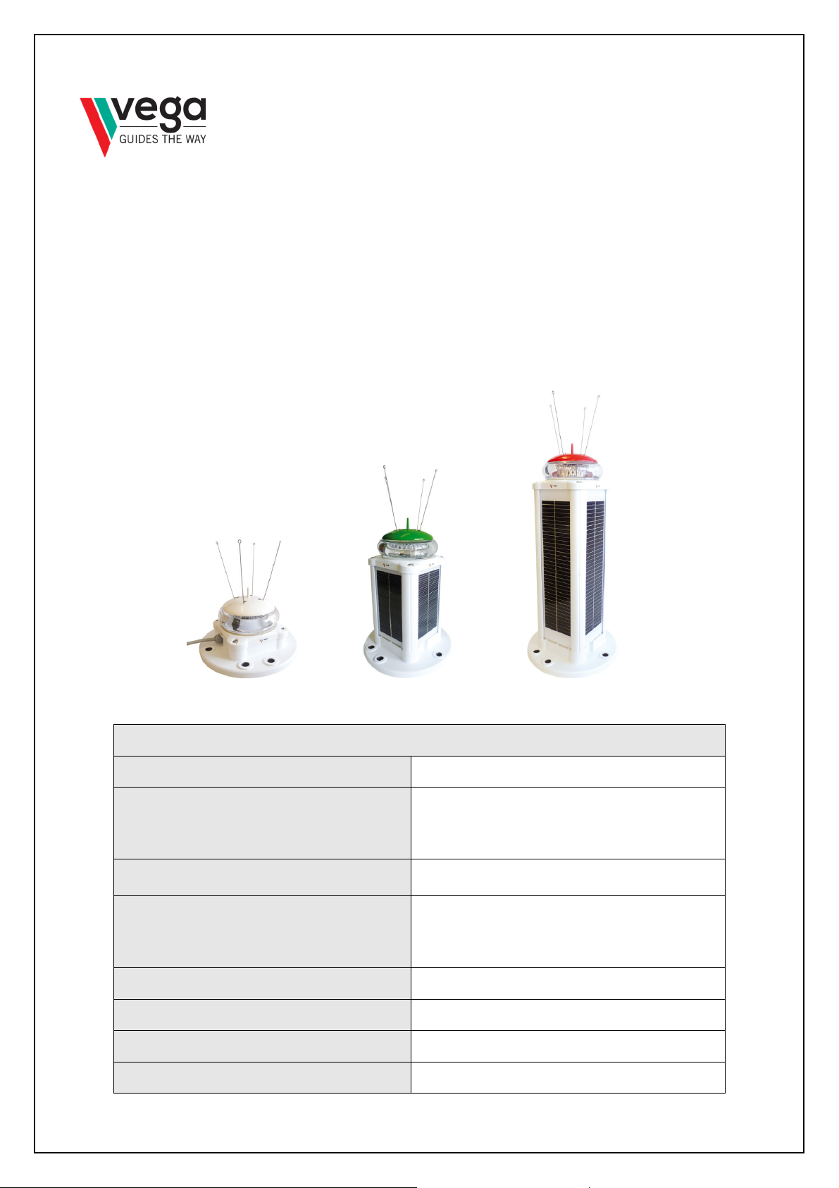
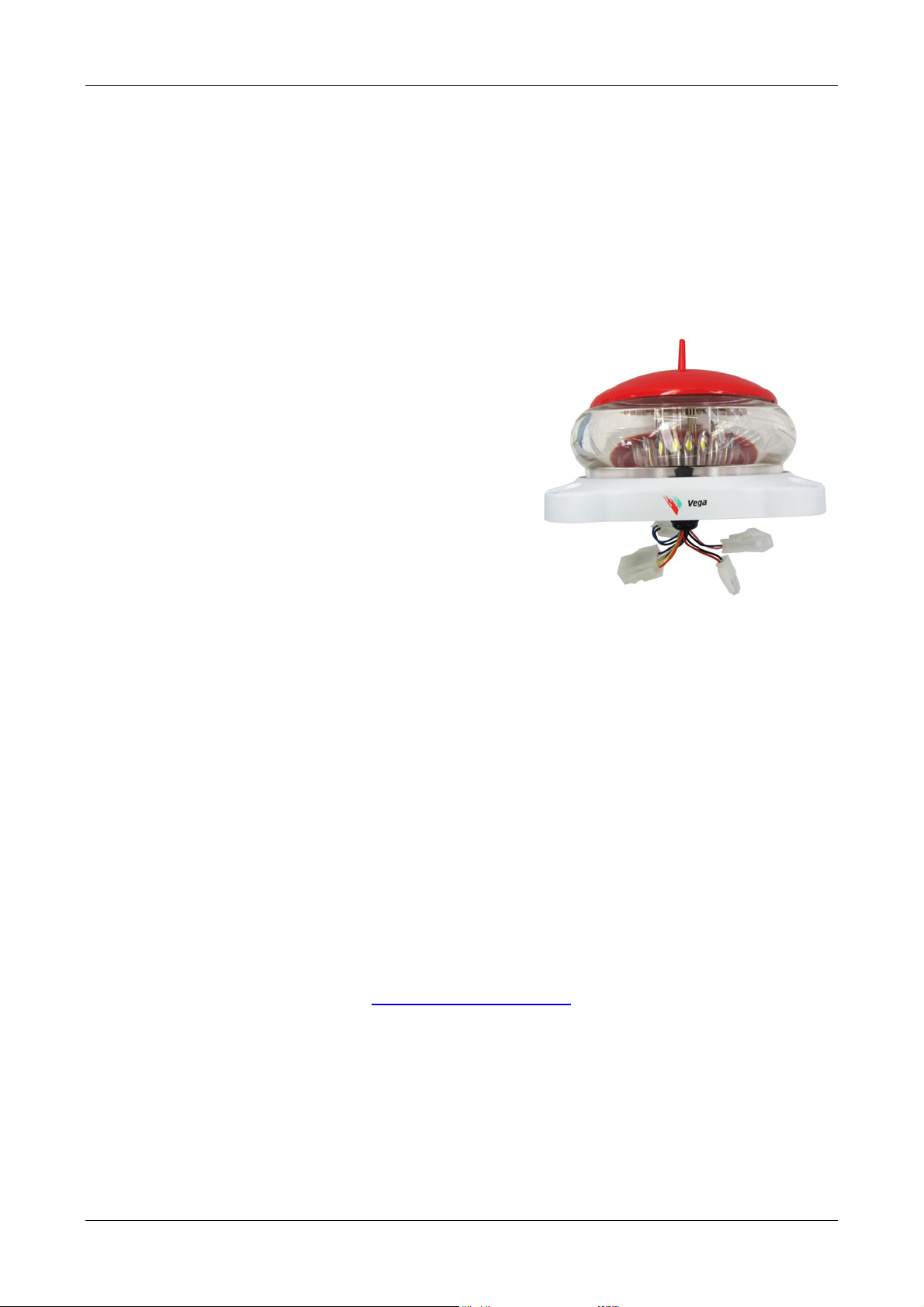
Introduction to the VLB-5X LED Beacon...................................................................6
1.1 Options Available ................................................................................................................6
1.2 Additional Factory Options ..................................................................................................7
1.3 Approvals ............................................................................................................................7
2.0
Range and Power .....................................................................................................7
2.1 Effective Intensity Settings ..................................................................................................7
2.2 Automatic Schmidt Clausen Correction ...............................................................................7
3.0
Mechanical Description .............................................................................................9
3.1 Construction ........................................................................................................................9
3.2 Solar Body Breather Vent.................................................................................................. 10
3.3 Sealing .............................................................................................................................. 10
4.0
Electrical .................................................................................................................10
4.1 Electrical Connections....................................................................................................... 10
5.0
Battery Charging on VLB-5X SS and LS Beacons..................................................10
SECTION 2
SETTING UP AND USING THE VLB-5X BEACON.................................10
1.0
Getting Started........................................................................................................10
2.0
Solar Calculations ...................................................................................................10
3.0
Shipping of the VLB-5X...........................................................................................11
3.1 From the Factory............................................................................................................... 11
4.0
Infra-red Programming ............................................................................................11
5.0
The Initial Power Up................................................................................................11
5.1 Stand Alone Model ............................................................................................................ 11
5.2 Self Contained Model ........................................................................................................ 11
6.0
Programming...........................................................................................................11
7.0
Installing the VLB-5X Beacon .................................................................................12
7.1 Bird Spikes........................................................................................................................ 12
7.2 Wiring from VLB-5X-SA & SAP Stand Alone Beacon ........................................................ 12
7.2.1 VLB-5X Base Compartment .............................................................................................. 12
7.3 Mounting the VLB-5X Beacon ........................................................................................... 12
7.3.1 Levelling the Beacon ......................................................................................................... 13
7.3.2 Mounting Structure............................................................................................................ 13
8.0
VLB-5X Factory Options .........................................................................................13
8.1 Hardwire Synchronization.................................................................................................. 13
8.2 Internal GPS Synchronization............................................................................................ 14
8.3 Alarm Monitor wire ............................................................................................................ 14
8.4 Data Port........................................................................................................................... 14
SECTION 3
MAINTENANCE .......................................................................................14
1.0
Maintenance Cleaning ............................................................................................14
2.0
Inspection Check.....................................................................................................14
3.0
Changing the Battery on Self Contained Models.....................................................15
SECTION 4
PROGRAMMING......................................................................................15

Instruction Manual VLB-5X LED Beacon © Vega Industries Ltd, Aug 2017
VLB-5X LED Beacon Page 5 of 53 VLB-5X V1.2
1.0
Programming Methods............................................................................................15
1.1 Using the Vega Remote TVIR Programmer....................................................................... 16
1.2 Using a Computer ............................................................................................................. 16
2.0
Default Settings.......................................................................................................16
3.0
Programming Syntax...............................................................................................16
4.0
Visual Feedback when using the TVIR Programmer...............................................17
4.1 The VLB-5X Will Not Enter Programming Mode ................................................................ 18
4.2 Becoming Familiar with the Syntax and Flash Feedback................................................... 18
4.3 Deciding what Settings are required .................................................................................. 20
4.3.1 Programming or Reading Multiple Settings........................................................................ 20
5.0
Programming Features ...........................................................................................20
5.1 Flash Character................................................................................................................. 20
5.2 Custom Flash Character.................................................................................................... 21
5.3 Day/Night Use of the Light................................................................................................. 21
5.4 Intensity Settings ............................................................................................................... 21
5.5 Synchronising Options....................................................................................................... 22
5.5.1 Additional Sync Options .................................................................................................... 22
5.6 Operation Mode................................................................................................................. 23
5.6.1 Auto Leave Storage........................................................................................................... 23
5.6.2 Auto Storage ..................................................................................................................... 23
5.7 Programming Mode........................................................................................................... 24
5.8 Battery Thresholds ............................................................................................................ 24
5.9 System Checks ................................................................................................................. 24
5.10 Security PIN Number......................................................................................................... 25
5.11 Calendar............................................................................................................................ 25
User Notes.........................................................................................................................28
Appendix A
Programming Table ................................................................................29
Appendix B
VLB-5X Intensity Settings And Currents ..............................................33
Appendix C
Worksheet for a Custom Character.......................................................37
Appendix D
VLB-5X Settings......................................................................................38
Appendix E
VLB-5X Solar Power Calculation example............................................39
Appendix F
Electrical Connections to VLB-5X Beacon ...........................................42
Appendix G
VLB-5X Beacon Dimensions..................................................................44
Appendix H
7° Marine light Vertical Divergence Profiles .........................................46
Appendix I
Specifications of VLB-5X Beacon .........................................................47
Appendix J
Flash Character Table with Programming Codes ................................50
Appendix K
VLB-5X Beacon Product Codes.............................................................53

Instruction Manual VLB-5X LED Beacon © Vega Industries Ltd, Aug 2017
VLB-5X LED Beacon Page 6 of 53 VLB-5X V1.2
SECTION 1 OVERVIEW OF THE VLB-5X LED BEACON
1.0 Introduction to the VLB-5X LED Beacon
The VLB-5X (next generationVLB-67/VLB-5) includes a new robust battery technology and an
increased optical range. The benefits of the new Lead Crystal® Battery (LCB) include improved
lifetime in hot climates, improved capacity in cold climates and better tolerance to running flat.
The user can also program many features using the TVIR remote programmer. If it is uncertain
how the beacon has been programmed, the VLB-5X can be reset to the factory default settings.
The procedure to do this is detailed in Section 4, Clause 5.6
For the self-contained solar powered models of the VLB-5X beacon it is critical that the solar
irradiation for the location where the beacon is to be used is checked to ensure that there is
enough energy available to support the intended range, and flash character. Vega provides an
online calculator for the VLB-5X on www.vega-navigation.com to assist in the correct usage of the
VLB-5X. Please note that reducing the range and the duty cycle of the beacon can lower the
power requirement.
1.1 Options Available
There are three lens options for the VLB-5X beacon.
•The 7° divergence (±3.5°) symmetrical lens provides a horizontal fan beam for marine
beacon applications.
•The obstacle lens is an asymmetrical lens with the peak intensity occurring at +8° above
the horizontal and is designed to provide the beacon profile required for aircraft hazard
lights for ICAO Type A and Type B and for use as bridge marking lights.
•The FAA lens is made to meet the FAA 810 optical requirements.
The VLB-5X 7° marine beacon can be programmed for an operating range at:
•2 to 5.5NM at 0.74T visibility and
•2.25 to 7NM at 0.85T visibility
The VLB-5X obstacle light can be programmed between 1 and 54 candela effective intensity,
measured at +6 and +10 degrees from the horizontal. ICAO Aircraft hazard light requires the
following intensity at these angles:
•Type A hazard light 10 candela
•Type B hazard light 32 candela
The VLB-5X wreck light is IALA-compliant and offers a yellow and blue alternating light.
•
Flash character: Blue 1.0s + 0.5s + Yellow 1.0s + 0.5s = 3.0s
•
Hard-wired and GPS sync options
For the VLB-5X, there are five LED colours available: red, green, white, yellow, and blue. Each
colour has a different power requirement to achieve any particular intensity. Detail on power
consumption is provided in appendix B.
The Vega VLB-5X beacon is available in four models.
Body size
Solar Panel Capacity
Battery Capacity
SA=Stand Alone Nil Nil
SS=Standard Solar 8Watt (4x 2W panels) 12Ah
LS1=Large Solar 16Watt (4x 4W panels) 12Ah
LS2=Large Solar` 16Watt (4x 4W panels) 2x12Ah

Instruction Manual VLB-5X LED Beacon © Vega Industries Ltd, Aug 2017
VLB-5X LED Beacon Page 7 of 53 VLB-5X V1.2
The self-contained solar power models use a 12VDC long life lead crystal battery that can operate
down to low temperatures. Only use a Vega VLB-5X replacement battery (EBAT-LCB-12V-12AH).
The Standard Solar (SS) unit will cover most self-contained applications. The large solar LS
models are available for use in higher latitude and/or high duty applications.
For bridge marking application (VLB-5X-SAP and VPP-5X), the VLB-5X obstacle lens is mounted
separately from the solar power pack. This allows the light head to be mounted under a bridge
while locating the power pack where it can receive solar energy. The separate components consist
of the stand-alone (SAP) light head and VPP-5X power pack. Note that the solar power regulator is
located in the lantern and not in the VPP-5X power pack. In applications requiring more solar
power, the solar power pack can be substituted with the larger capacity VPP-5X.
The VLB-5X is designed with many features to allow the user to customise the beacon for any
application. Programming is done using the Vega Remote-02 infrared programmer, which needs to
be ordered separately.
1.2 Additional Factory Options
Additional Factory options for the VLB-5X:
•GPS synchronising.
•Data Plug incorporating RS232 or RS422 data connection, alarm/monitor wire, and sync
wire
•External charging plug and sync wire for self-contained models SS and LS
•Alarm/Monitor output (beacon healthy)
Note: Hard wire synchronisation is provided as standard on the SA model
1.3 Approvals
The VLB-5X (approved under the former name of VLB-67) LED beacon has been approved under
US Coast Guard regulations CFR33 part 67 for use as a Class B or C light for artificial islands and
structures in the Gulf of Mexico (USCG District 8).
2.0 Range and Power
2.1 Effective Intensity Settings
Effective intensity is the intensity required to see a continuously “on” light (fixed character) at a
certain distance. For example 37 Candela is required to see a fixed “on” light at 4 NM when the
atmospheric visibility is 10 miles (0.74T).
The VLB-5X beacon supports a number of effective candela settings.
Appendix B of the manual provides the following information:
•The effective intensity settings available for each colour
•The current the beacon will use at each intensity
•The peak candela and peak current of each colour
While the VLB-5X is normally only used at night it is possible to operate the beacon during the day
using a different intensity setting than is used at night.
2.2 Automatic Schmidt Clausen Correction
When a light is flashed, the intensity must be increased to maintain the lights visibility at the
required distance. This increase of intensity is the “peak” intensity for the flash character. The
VLB-5X automatically handles this process according to the Schmidt Clausen multiplier for LED
lights: (Flash period in seconds+0.2)/Flash period in seconds

Instruction Manual VLB-5X LED Beacon © Vega Industries Ltd, Aug 2017
VLB-5X LED Beacon Page 8 of 53 VLB-5X V1.2
The VLB-5X beacon will not operate above its maximum candela capability. When programming a
flash character the user should check that the peak candela required for a flash character at the
required range is below the maximum intensity. The VLB-5X will cap the intensity at the maximum
candela allowed, reducing the range of the light.

Instruction Manual VLB-5X LED Beacon © Vega Industries Ltd, Aug 2017
VLB-5X LED Beacon Page 9 of 53 VLB-5X V1.2
3.0 Mechanical Description
3.1 Construction
The common parts of the VLB-5X are the beacon head, the
base, and the connecting seal.
The stand-alone (SA) model consists of these 3 parts and
has a 1.5 metre 3 core cable fitted to provide the power
connection for the beacon. This cable also contains the
wire for the sync signal.
The
standard solar (SS) and large solar (LS1 and LS2)
self-contained models have the solar power system
consisting of solar panel assembly and battery.
The plastic body and base of the VLB-5X beacon is made
from nylon and has a 30 percent glass fill. The coloured
top of the beacon is made from ASA plastic. The lens is
moulded from optical grade acrylic.
The VLB-5X LED beacon is assembled and sealed using
self-tapping fasteners into the glass filled nylon parts. This
assembly method is not designed for frequent disassembly
and reassembly of the beacon. There should be no need
to disassemble the beacon other than to change the
battery once or twice during the beacon’s lifetime.
Disassembly of the beacon should be kept to a minimum to
ensure the proper sealing.
Beacon head
Base
VLB-5X-SA Stand Alone
VLB-5X-SS Standard Solar
Seal
VLB-5X-LS2 Large Solar
Solar Body
VLB
-
5X
-
LS1
Large Solar
Battery
Battery
Solar Body

Instruction Manual VLB-5X LED Beacon © Vega Industries Ltd, Aug 2017
VLB-5X LED Beacon Page 10 of 53 VLB-5X V1.2
3.2 Solar Body Breather Vent
The solar body has been fitted with a membrane vent to allow pressure equalization, and to
release any hydrogen gas that may build up from the battery. The membrane vent is located at the
top of the body behind one of the solar panels. The vent should not be tampered with as any
damage may cause water to enter the battery compartment.
3.3 Sealing
The beacon is sealed against the ingress of moisture, dust, insects and other environmental
contaminants. Because the beacon does not need to be opened for programming, these seals can
remain undisturbed for extended periods. If the power pack is opened for inspection or to change
the battery, do not let any water accumulate in the battery compartment.
4.0 Electrical
4.1 Electrical Connections
There are four connectors at the bottom of the VLB-5X
lantern. These are used to connect the battery/power
supply, solar panels, data port, sync wire, and monitor
wire. What connectors are used on any VLB-5X Beacon
will depend on the options ordered.
There should be no need for the user to access these
connections other than when a battery is being replaced
on the self-contained units.
Details of the electrical connections are provided in
Appendix F.
5.0 Battery Charging on VLB-5X SS and LS Beacons
The solar charger in the VLB-5X beacon monitors the temperature and the voltage and will charge
the batteries when the voltage level at the solar panels exceeds the voltage of the battery.
Protection is provided to prevent the overcharging of the battery.
The solar charger is designed for the lead crystal battery. The battery on the VLB-5X has been
specifically designed for the mounting configuration used in the VLB-5X. If a replacement battery
is required please obtain the correct battery from Vega or one of Vega’s distributors. Other
batteries may cause damage to the beacon.
SECTION 2 SETTING UP AND USING THE VLB-5X BEACON
1.0 Getting Started
•If using a self-contained model check there is sufficient solar energy at the location to
support the range and flash character (see Appendix E). Alternatively use the selector
program on the Vega website www.vega-navigation.com under “Calculators”
•For self-contained models change the operating mode from “storage” to “normal”
•Program the beacon (Section 4).
•Fit the bird deterrents (Clause 7)
•Install the VLB-5X LED marine beacon (Clause 7)
•Check the beacon is working (Section 3)
2.0 Solar Calculations
If the solar calculations are being done manually, it is necessary to determine the energy
contribution for each solar panel taking into account the azimuth and inclination angles. Examples

Instruction Manual VLB-5X LED Beacon © Vega Industries Ltd, Aug 2017
VLB-5X LED Beacon Page 11 of 53 VLB-5X V1.2
for the solar calculations are provided in appendix E. The solar panels should provide more
energy than the beacon uses during the worst solar month of the year.
The 4 solar panels on the VLB-5X beacon are mounted 90 degrees apart from each other in
azimuth. The inclination of the solar panels is 90 degrees from the horizontal.
3.0 Shipping of the VLB-5X
3.1 From the Factory
The VLB-5X beacon will be delivered with factory default settings. The default settings are
detailed in appendix A. Please note the following defaults:
•TVIR Remote-02 programming only. The IRDA port will need to be enabled to program the
beacon with a Computer.
•Self-contained units will be shipped in storage mode in order to
maintain the battery charge. The operating mode will need to be
changed to “normal” in order to get the beacon operating
4.0 Infra-red Programming
The infrared receiver for programming the beacon is located behind the
LED ring. To program the beacon, point the Vega TVIR programmer or
the Vega IRDA sensor at the lens. Best results can be achieved by using
the programmers at the position indicated in the diagram.
5.0 The Initial Power Up
5.1 Stand Alone Model
At power-on when a battery is first connected, the beacon will remain inactive for about 30
seconds then start in night mode with the beacon flashing with the programmed flash character.
•After a further 16 to 20 seconds the beacon will begin to monitor the ambient light level. If
day is detected and the beacon is set for night operation only the beacon will turn off.
•After a further 14 seconds the beacon will begin to monitor the voltage for the low level
threshold (factory setting 11 Volts). If the threshold is reached the beacon will turn off. The
beacon will not return to normal operation until the voltage is above high voltage threshold
(factory setting 12.8 volts).
If the battery terminals (+ / -) are connected in reverse the beacon will not power up. No damage
will be caused by reverse connecting the beacon.
5.2 Self Contained Model
The self-contained models of the VLB-5X beacons are shipped from the factory in “storage mode”
and must be changed to “normal mode” to operate.
When in “storage mode”, the TVIR receiver in the beacon only looks for the programmer every 60
seconds. To get the self-contained unit into “normal mode”:
•Hold the red button down for up to 60 seconds until the VLB-5X flashes four times to
indicate the beacon is in program mode.
•Enter 15000 ensuring the beacon flashes between each key entry from the programmer.
•The VLB-5X will flash when each key of the programmer is pressed
•The VLB-5X will then flash back the complete code 15000 in a series of flashes
•If no other programming instructions are done the beacon will respond with 2 quick flashes
followed by as space then two more quick flashes and leave the programming mode.
See Section 4 on how the Beacon responds on entering and leaving the program mode.

Instruction Manual VLB-5X LED Beacon © Vega Industries Ltd, Aug 2017
VLB-5X LED Beacon Page 12 of 53 VLB-5X V1.2
6.0 Programming
The VLB-5X beacon has many program options and settings. It is important that the user
understands the programming syntax and the options available. It is suggested the user works
through the programming examples provided in Section 4 and the description on the various
options and features before deciding the setup of the Beacon for a particular application
7.0 Installing the VLB-5X Beacon
7.1 Bird Spikes
The beacon is supplied with 4 stainless steel bird spikes.
Each spike is attached to the lid by a 4 gauge x ¼” (6mm) stainless steel screw fixed through the
loop on the end of the wire. It is important that only the Vega supplied screws are used for this
purpose as longer or larger diameter screws may puncture the lid and allow water inside the
beacon.
7.2 Wiring from VLB-5X-SA & SAP Stand Alone Beacon
The power and synchronizing connections are provided in a 1.5-meter length of 3-core 0.75mm²
cable. Wiring identification is as follows:
The VLB-5X SA Beacon is a sealed unit. If shortening the power cable the user must tin each
cable core and reseal both external sheath and internal cores with
heat shrink and marine sealant.
7.2.1 VLB-5X Base Compartment
The base of the VLB-5X beacon is designed to provide space to fit
a AC to DC switch-mode power supply to allow the VLB-5X-SA
Stand Alone model to be mains powered. Vega will only supply
the stand alone model as a 12VDC unit and if a mains supply is
required the needs to be done by the user.
The user has the responsibility to ensure the mains power
conversion meets the local electrical regulation requirements.
The base is fitted with mounting points to accept a TRACO AC/DC
converter. This unit can be purchased from RS Components
(www.RS-Online.com) part number #RS 3221840.
The space in the base can also be used for other user equipment such
as for a monitoring interface or for sync signal conversion.
The VLB-5X beacon is a sealed unit. Where any item is fitted into the
base of the beacon extreme care should be taken to ensure the sealed
integrity of the beacon is maintained.
7.3 Mounting the VLB-5X Beacon
SA Unit
SAP Unit
Brown +12 Volts Battery positive Battery positive
Blue 0 Volts Battery negative Battery negative
Green Sync Do not connect to battery negative
unless using advanced sync functions
N/A
White Solar
Power
N/A For connecting to VPP-5X Solar
Power Pack

Instruction Manual VLB-5X LED Beacon © Vega Industries Ltd, Aug 2017
VLB-5X LED Beacon Page 13 of 53 VLB-5X V1.2
The base of the VLB-5X beacon has been designed for 3 or 4 holes mounting on a 200mm
diameter PCD. The base has through holes sized to take 316 Stainless steel M12 (1/2” UNC) bolts
or rod. The mounting holes are fitted with stainless inserts to prevent compression of the plastic
base when the fasteners are tightened.
7.3.1 Levelling the Beacon
The mounting surface needs to be level to ensure the VLB-5X has a horizontal beam. This can be
checked by placing a builder’s level on the mounting surface then moving the level 90 degrees at a
time checking the surface is level in at least two directions. If the mounting surface is not level
take appropriate measures to ensure it is level before permanently installing the beacon.
Alternative levelling mechanisms can be used, such as adjustable rods. If the mounting surface
cannot provide 3 or 4 holes mounting on a 200mm PCD an adapter plate would be required.
When the beacon is mounted on a floating structure (buoy), the beacon needs be level when the
buoy is floating freely in calm air and water.
7.3.2 Mounting Structure
Movement of the mounting structure needs to be constrained to a level where the VLB-5X beacon
can be visible to the intended user. This includes the sway on a fixed structure and the roll of a
buoy.
The vertical divergence of the VLB-5X beacon is 7 degrees. At ± 3.5°the intensity is at 50%, and
at ± 7.0°the intensity is approximately 10% of the peak intensity
8.0 VLB-5X Factory Options
All options are factory installed and must be included in the purchase order. None of the options
can be fitted in the field after the VLB-5X beacon has been manufactured.
8.1 Hardwire Synchronization
The VLB-5X-SA stand alone beacon comes with the hardwire sync wire included in the power
cable. Because of the nature of the self-contained beacon no external wiring is supplied with the
standard option.
The Vega hardwire sync operates as a positive to negative transition. The start of the flash
character can be delayed between 0 and 9.9 seconds should it be desirable to have a different
start time to other beacons connected to the synchronising wire.
The sync wire can provide additional control such as turning the beacon off when grounded. This
can be useful when a standby light option is required. Refer to section 4 clause 5.5.1.
Other beacon manufacturers may not use a negative transition signal and will not be able to
synchronise with Vega beacons. If there is a requirement to synchronise with beacons with a
positive transition signal it may be possible to use the signal inverter module (Vega 167-600). The
VLB-5X beacon will only operate in Slave Sync mode when connected to the signal inverter
module.

Instruction Manual VLB-5X LED Beacon © Vega Industries Ltd, Aug 2017
VLB-5X LED Beacon Page 14 of 53 VLB-5X V1.2
8.2 Internal GPS Synchronization
It is necessary to take into account the power consumption of the GPS unit in any power
calculations. The GPS sync unit only operates when the beacon is programmed to run (night or
day/night). The clock is updated from the GPS satellites every 20 minutes and the typical
acquisition time is around 2 minutes. The GPS current is detailed in Appendix B
If GPS synchronisation is required for a number of beacons that are in close proximity it is possible
to fit only one GPS unit and to connect the other beacons using hardwire synchronising.
8.3 Alarm Monitor wire
The alarm monitor wire is used to provide an indication when the VLB-5X is not working. This
alarm monitors the current of the beacon and the supply voltage.
Output is connected to ground when
•No voltage or low voltage is present.
•No LED current or low current is detected when the VLB-5X beacon should be on.
•Alarm is being tested using Operation mode 1-5-007 (Section 4 Clause 5.6)
The monitor output operates as an electronic relay with one side connected to ground (battery
negative). A 0 to 20VDC can be applied to the alarm/monitor output. The maximum current the
monitor output can handle is 400mA DC. Do not connect to battery positive. For additional details
refer to the specification section.
8.4 Data Port
The RS232/RS485 data port can operate continuously or “on demand. The “on demand” mode
uses less power than the continuous mode. When the data port is used the additional power must
be taken into account when calculating the overall power requirement if the VLB-5X.
The data port shares common circuitry with the IRDA port that is used for programming the VLB-
5X from a computer. Only one data port can be used by the VLB-5X at any time. Operation of the
data ports is selectable using the Vega Remote TVIR programmer.
Details of the data port protocol and the beacon parameters available are contained in Appendix G
SECTION 3 MAINTENANCE
1.0 Maintenance Cleaning
Vega LED beacons require little to no maintenance.
Solar panels on the VLB-5X SS and LS models should be inspected and cleaned occasionally to
ensure maximum solar energy capture. Use warm soapy water to wash the outside of the beacon
and rinse off with clean water. Do not use any solvent-based cleaner.
2.0 Inspection Check
Periodically check that the beacon remains firmly secured and level, and the mounting fasteners
are still in good condition. Investigate any corrosion and take appropriate preventive action.
The beacon can be tested by programming for the “test “mode or if daytime covering the lens
briefly to simulate night time operation. When the light is flashing, check it is displaying the correct
flash character.
Remember to remove any lens cover before leaving the site.

Instruction Manual VLB-5X LED Beacon © Vega Industries Ltd, Aug 2017
VLB-5X LED Beacon Page 15 of 53 VLB-5X V1.2
3.0 Changing the Battery on Self Contained Models
Ensure the correct replacement battery is being used. This should be an EBAT-LCB-12V-12AH
available from Vega or a Vega distributor.
It is recommended that the O-rings on the solar body seals be replaced at the same time as the
battery. The replacement battery will be shipped with two O-rings for the seal where the solar body
is opened. If additional O-rings are required, the part number for ordering is Oring130EPDM.
When new O-rings are fitted ensure they have a coating of silicon grease before reassembly.
To change the battery on the self-contained models of the VLB-5X:
•Unscrew the four screws holding the lantern head to the solar body.
•Lift off the lantern head ensuring the head seal with the two O-rings remains attached to the
lantern head.
•Unplug the battery cable and solar cables from the lantern head and set the lantern head
aside.
•Remove the battery and the foam packing.
•Unscrew the battery cable from the old battery and attach to the new battery.
•Fit the new charged battery as shown in the photo with the battery leads next to the solar
body vent and refit the foam packing making sure the vent is not blocked.
•Push the square foam packer between the battery (next to the screw terminals) and the
side wall of the beacon body.
•With the sealing ring containing the two O-rings attached to the lantern head, reconnect the
battery and solar cables to the lantern head. Arrange the cables inside the solar body and
under the foam packing so that the cables cannot interfere with the sealing ring.
•Carefully replace the lantern head onto the solar body keeping the lantern head as
horizontal as possible. Hold the cables and connectors in place with one hand as the
lantern head is put in place on the solar body with the other hand. Once the lantern head is
in place apply some pressure and check that it feels properly in place. If there is any doubt
about the position of the cables or connectors under the head, lift the lantern head and
repeat this step.
•Reattach the lantern head using the original 4 screws. The torque value for the assembly
screws is 2.2 to 2.4Nm. Using torque above this value will cause damage and prevent the
VLB-5X beacon from sealing properly.
•Visually check the beacon from all four sides to ensure the lantern head is level relative to
the base.
The self-contained versions of the VLB-5X
LED Marine Beacon are assembled and
sealed using self-tapping fasteners into
the glass filled nylon parts. This assembly
method is not designed for frequent
disassembly and reassembly of the
lantern. There should be no need to
disassemble the beacon other than to
change the battery once or twice during
the life of the product. Disassembly of the
beacon should be kept to a minimum to
ensure the proper sealing.
SECTION 4 PROGRAMMING
1.0 Programming Methods
There are two methods of programming the VLB-5X Beacon.

Instruction Manual VLB-5X LED Beacon © Vega Industries Ltd, Aug 2017
VLB-5X LED Beacon Page 16 of 53 VLB-5X V1.2
Red standby key, used to
enter programming mode.
IMPORTANT
Before attempting to use the programmer for the first
time, please pull the plastic insulating strip out of the
battery holder – you do not need to remove the battery
holder to do this.
The programmer will not work if the plastic strip is left in
place.
•Using the Vega remote TVIR programmer (Remote-02)
•Using a computer with the VLB-5X Programming Kit (Prog-01)
The beacon will be shipped with a default setting for programming with the remote TVIR
programmer. The programming mode will have to be changed to allow computer programming.
1.1 Using the Vega Remote TVIR Programmer
During programming the VLB-5X the beacon will provide visual feedback by flashing as the keys
are operated on the IR programmer. On completion of a program option the beacon will provide
visual feedback by repeating the code of the programmed function by a series of flashes.
1.2 Using a Computer
Two-way IRDA communication to the beacon is provided via a USB to IR adapter plugged into a
computer. All programming options for the VLB-5X will be displayed on the screen. The program
settings can be sent to or read from the VLB-5X beacon. Copies of the program settings can also
be saved or recalled from memory.
For computer programming please refer to the PROG-01 instruction manual. The programming
described in the rest of this manual relates to the infrared TVIR programmer only.
Computer programming of the VLB-5X is more straightforward than using the remote TVIR
programmer as all features of the beacon can be set at once and or can be verified by down
loading the settings from the beacon.
The VLB-5X has two data ports, IRDA and the RS232/RS485. The RS232/RS485 port is only
fitted if requested at time of order. The VLB-5X can only operate with one of the data ports at any
time. The port being used is selectable using the programming mode options. The IRDA data port
is required to be enabled to allow programming to occur from a computer.
When either the IRDA or RS232/RS485 port is enabled the VLB-5X will use more power. When
programming is finished the IRDA should be turned off before the Beacon is installed in order to
reduce the power consumption.
2.0 Default Settings
The VLB-5X beacon is delivered from the Factory with default settings. These settings are
detailed in Appendix A. If there is a need to return the light to the default settings use the option to
allow this in the in the “operating mode”.
3.0 Programming Syntax
All programming of uses the syntax of: OPERATION_FEATURE_VALUE
There are six OPERATION items
Numeric keypad, used to
configure the programmable
features of the light.

Instruction Manual VLB-5X LED Beacon © Vega Industries Ltd, Aug 2017
VLB-5X LED Beacon Page 17 of 53 VLB-5X V1.2
Programming Operation 1
Creating a Custom Character Operation 2
System Information Operation 3
Calendar Control Operation 4
Optional PIN code Operation 7
Read settings Operation 9
FEATURE items represent the features of the light such as flash character and intensity.
VALUES are the actual settings or value of the various features.
Appendix A of this manual provides a Table for the programming features of the VLB-5X beacon.
Please take the time to become familiar with the table before continuing.
4.0 Visual Feedback when using the TVIR Programmer
The VLB-5X will provide visual feedback of the programming instructions it receives from the TVIR
programmer. It is important to understand the feedback that is provided to ensure the light will be
programmed correctly.
Programmer Keys Light response
Enter Programming Mode
By pressing red standby key for 5 seconds
4 quick flashes (0.1sec on 0.1sec off)
If the VLB-5X has been programmed for
Calendar or auto storage mode the flash
response will be different.
Numeric key when programming 1 flash for each key pressed
When programming code recognised
The 3 or 4 digit value code is repeated using a
series of flashes of 0.1sec on and 0.1 sec off
with a gap of 0.5 sec between each number of
the code. A zero is represented by a 2 second
on flash.
Proper termination of custom character
programming: the feedback code will be 000
When programming code is not recognised
3 quick flashes (0.1sec on 0.1sec off)
The light will remain in programming mode
waiting for a new programming instruction.
Exiting Programming mode
No programming activity for 10 Seconds
The light will give two quick flashes followed by
a short pause followed by another two quick
flashes.
If the VLB-5X has been programmed for
Calendar or auto storage mode, the flash
response will be different.
After this, the beacon will resume normal
operation. The light will flash its character for
16 seconds while it checks the day/night
settings. If it is daytime and the light is set to
operate at night only the light will turn off.

Instruction Manual VLB-5X LED Beacon © Vega Industries Ltd, Aug 2017
VLB-5X LED Beacon Page 18 of 53 VLB-5X V1.2
The flash sequence for entering and exiting the programming mode is adjusted if the VLB-5X has
been programmed to use calendar or Auto Storage. This has been done in order to provide an
indication that the VLB-5X has been programmed in either of these modes. The background
power consumption of the VLB-5X will be higher if these functions are used. Flash sequence
when entering and leaving the program mode is as follows:
Action Flash Sequence
Entering TVIR Mode Normal 4 quick flashes (0.1sec on 0.1sec off)
When Calendar or Auto Storage is being used
2 slow flashes (0.3sec on 0.3sec off)
2 quick flashes (0.1sec on 0.1sec off)
2 slow flashes (0.1sec on 0.1sec off)
Exiting TVIR Mode Normal
2 quick flashes (0.1sec on 0.1sec off)
1 gap of (0.3 sec)
2 quick flashes (0.1sec on 0.1sec off)
When Calendar or Auto Storage is being used
2 quick flashes (0.1sec on 0.1sec off)
1 gap of (0.3 sec)
2 slow flashes (0.3sec on 0.3sec off)
4.1 The VLB-5X Will Not Enter Programming Mode
If you find the VLB-5X will not enter the programming mode it will be caused by one of 4 reasons:
•The battery in the TVIR programmer is missing, or the plastic battery insulator has not been
removed, or the battery has low voltage.
•There is no 12VDC supply connected to the light.
•The light has been set to storage or calendar mode and is hibernating. In this case the red
button may have to be held for 60 seconds in order for the VLB-5X to see the TVIR
programmer. Once in programming mode the operating or calendar settings can be checked or
reprogrammed. Refer Clause 5.6 for the operating modes and clause 5.11 for the calendar
settings.
•Beacon needs a security PIN to allow programming. Refer clause 5.10.
4.2 Becoming Familiar with the Syntax and Flash Feedback
If you have not used the Vega TVIR Programmer before, spend some time learning how the light
will respond to the various programming actions. Make sure the light is connected to a 12VDC
supply and experiment with the following.
Enter and Exit Program mode
1. Enter program mode
Press the red standby button
for 5 seconds
The light will give 4 quick flashes to indicate it has entered programming
mode
If the VLB-5X has been programmed for Calendar or auto storage mode, the
flash response will be different.
2. Exit program mode
Leave the programmer idle for
10 seconds
The light will give two quick flashes followed by a short pause followed by
another two quick flashes.
If the VLB-5X has been programmed for Calendar or auto storage mode, the
flash response will be different.
After this it will resume normal operation. The light will flash its character for
16 seconds while it checks the day/night settings. If it is daytime and the
light is set to operate at night only the light will turn off.
Program a Flash Character with a flash character of Q 1s 0.4. (0.4 “on” 0.6 “off”)
To program this Flash Character, find the three-digit code from Appendix K, “Flash character table
with program codes”. (Flash Q 1s 0.4 = code 602). Determine the programming Syntax from
Appendix A for the setting:
Operation =Programming =1
Feature =Flash Character =0
Value =Code =602

Instruction Manual VLB-5X LED Beacon © Vega Industries Ltd, Aug 2017
VLB-5X LED Beacon Page 19 of 53 VLB-5X V1.2
The programming sequence to enter this flash character is 10602
1. Enter programming mode
Press the red standby button
for 5 seconds
The light will give 4 quick flashes to indicate it has entered programming
mode
If the VLB-5X has been programmed for Calendar or auto storage mode, the
flash response will be different.
2. Enter the programming
sequence for the flash
character (10602)
The light will flash once each time a key on the programmer is operated.
When the sequence is completed and accepted the light will repeat the value
602 in a series of flashes. Six quick flashes followed by a 0.5sec gap
followed by a 2 second flash (for a zero) followed by a 0.5 second gap
followed by two quick flashes
3. Exit programming mode
Leave the programmer idle for
10 seconds
The light will give two quick flashes followed by a short pause followed by
another two quick flashes.
If the VLB-5X has been programmed for Calendar or auto storage mode, the
flash response will be different.
After this it will resume normal operation. The light will flash its character for
16 seconds while it checks the day/night settings. If it is daytime and the
light is set to operate at night only the light will turn off.
Create a programming error by attempting to enter an invalid Operation Mode code 003
Determine the programming Syntax from Appendix A for the setting:
Operation =Programming =1
Feature =Operation Mode =5
Value =Code =003
The programming sequence to enter this Operation Mode is 15003
•Enter programming mode
Press the red standby button for 5 seconds
The light will give 4 quick flashes to indicate it has
entered programming mode
If the VLB-5X has been programmed for Calendar or
auto storage mode, the flash response will be different.
•Enter the programming sequence for the
Operation Mode (15003)
The light will flash once each time a key on the
programmer is operated.
When the sequence is completed the value will be
rejected and an error indicated by 3 quick flashes.
The beacon will then return to programming mode and is
ready for a new instruction.
•Exit programming mode
Leave the programmer idle for 10 seconds
The light will give two quick flashes followed by a short
pause followed by another two quick flashes.
If the VLB-5X has been programmed for Calendar or
auto storage mode, the flash response will be different.
After this it will resume normal operation. The light will
flash its character for 16 to 20 seconds while it checks
the day/night settings. If it is daytime and the light is set
to operate at night only the light will turn off.

Instruction Manual VLB-5X LED Beacon © Vega Industries Ltd, Aug 2017
VLB-5X LED Beacon Page 20 of 53 VLB-5X V1.2
Read System Information
To read the current level of the battery or 12VDC supply, determine the Syntax from Appendix A:
Operation =System Checks =3
Feature =Battery Voltage =1
The programming sequence to get the information is 31
1. Enter programming mode
Press the red standby button for 5 seconds
The light will give 4 quick flashes to indicate it has
entered programming mode
If the VLB-5X has been programmed for Calendar or
auto storage mode, the flash response will be different.
2. Enter the programming sequence for the
information (31)
The light will flash once each time a key on the
programmer is operated.
When the sequence is completed and accepted the light
will provide the voltage level in a series of flashes
(13.2VDC). One quick flash followed by a 0.5sec gap
followed by 3 quick flashes followed by a 0.5 second gap
followed by two quick flashes.
3. Exit programming mode
Leave the programmer idle for 10 seconds
The light will give two quick flashes followed by a short
pause followed by another two quick flashes.
If the VLB-5X has been programmed for Calendar or
auto storage mode, the flash response will be different.
After this it will resume normal operation. The light will
flash its character for 16 to 20 seconds while it checks
the day/night settings. If it is daytime and the light is set
to operate at night only the light will turn off.
4.3 Deciding what Settings are required
Appendix D contains tables for noting the program settings of the VLB-5X.
As the VLB-5X is delivered from the factory with default settings and it is only necessary to
program the settings that need to be changed. The “Read Settings” feature can be used to note
the values already programmed.
Once the required settings are known use the second table in Appendix D to note the correct
syntax and programming code from programming tables in Appendix A.
4.3.1 Programming or Reading Multiple Settings
Each feature can be programmed one at a time, as done in the examples given in Clause 4, by
entering and exiting the program mode each time a feature is programmed. However, this can be
time consuming to enter multiple settings, as it is necessary to wait for the VLB-5X to flash its
response and return to normal operation before entering the programming mode again.
To avoid this difficulty the various settings can be programmed sequentially. Once the VLB-5X has
accepted a program sequence and has flashed back the value code, the next program sequence
can be entered. If there is a delay of more than 10 seconds after the confirmation flashes before
entering the next program sequence the VLB-5X will exit the program mode.
The use of the table in Appendix D will allow all the programming sequences to be pre-determined
and allow for a quick entry of the program settings without the need to exit the programming mode.
5.0 Programming Features
(Refer to Appendix A for the full list).
5.1 Flash Character
Vega lights are pre-programmed with 246 standard characters represented by a 3-digit code XYY.
The first digit of the code represents a flash type such as 1YY for Isophase characters. If flash
characters are required that are not included in the standard set these can be loaded as a custom
Table of contents
Other Vega Industries Marine Equipment manuals