Vingtor ETB-5 User manual

Command Talk-Back & Public Address System
ETB-5 / ETB-10 / ETB-10A / ETB-100 / ETB-100A
A100K11162 v1TECHNICAL MANUAL

About this Document
Document Scope
This document is intended for qualied technicians who will install and
commission the ETB-5/ETB-10/ETB-10A/ETB-100/ETB-100A Command Talk-
Back & Public Address system on marine vessels. It also provides the end-user
with all necessary instructions for operating the ETB central unit.
The following central units (panel version 8.0) are available for the ETB system:
Product Item Number
ETB-5 Central Unit, Panel Mounted, 5 Lines 3005020022
ETB-10 Central Unit, Panel Mounted, 10 Lines 3005020018
ETB-10A Central Unit, Panel Mounted, Public Address, 10 Lines 3005020021
ETB-100 Central Unit, Panel Mounted, 10 Lines 3005020019
ETB-100A Central Unit, Panel Mounted, Public Address, 10 Lines 3005020020
Publication Log
Rev. Date Author Description
1.0 21.11.2011 HKL
Panel version 8.0
Supersedes installation manuals for
ETB-5/ETB-10 (A100K10868) and ETB-
100 (A100K10867)
Related Documentation
Doc. no. Documentation
A100K11163 ETB Command Talk-Back & PA User Guide
Rules & Regulations
The ETB-5/ETB-10/ETB-10A/ETB-100/ETB-100A system and its components
has been tested according to following regulations:
●IEC 60533: Second edition, 1999
“Electrical and electronic installation in ships - Electromagnetic compatibility”
●IEC 60945: Fourth edition, 2002
“Maritime navigation and radio communication equipment and systems -
General requirements - Methods of testing and required test results”
●IACS E10: Corr.1 July 2003
“Unied environmental test specication - Testing procedure for electric
control and monitoring, safety and protection, onboard computer based
systems and peripherals, loading instruments, internal communication and
other electrical equipment as considered appropriate”
● Complies with DNV ship requirements - “Main Class Cargo Ship Vessels for
two way voice communication”
LDoes not comply with DNV ship requirements “C500 Nautical safety for two-
way voice communication”

3
ETB Command Talk-Back & Public Address System
Installation & Operation Manual
A100K11162 v1
Contents
1 System Overview ............................................................................................................5
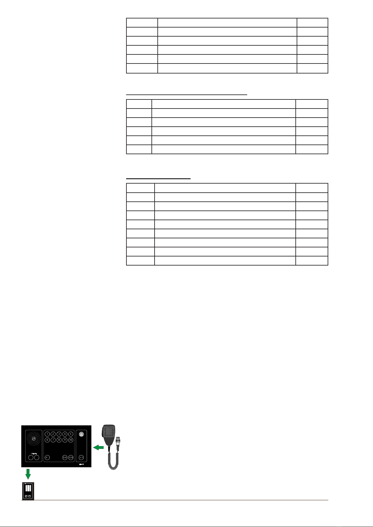
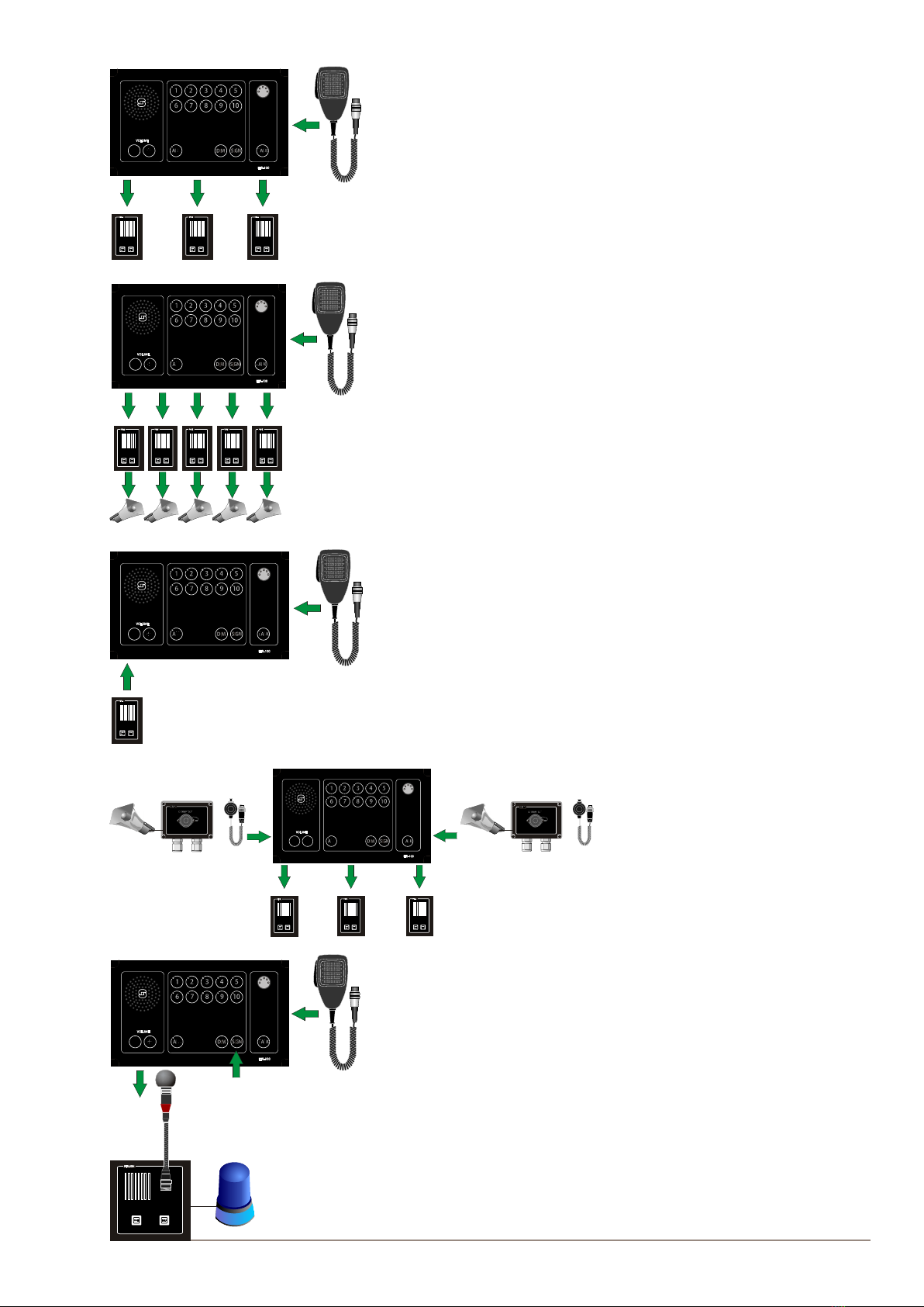
1.1 ETB-10 System Conguration ..................................................................................5
1.2 ETB-100 System Conguration ................................................................................6
1.3 Features ...................................................................................................................7
1.4 System Components.................................................................................................7
1.5 Functions ..................................................................................................................8
1.5.1 General ............................................................................................................8
1.5.2 Line Selection / Single Call ..............................................................................8
1.5.3 Group Call........................................................................................................9
1.5.4 All Call..............................................................................................................9
1.5.5 Call from a Substation......................................................................................9
1.5.6 Parallel Communication ...................................................................................9
1.5.7 Signal and Extra Signal Device for Substations...............................................9
1.5.8 Extra Signal in the ETB Central Unit..............................................................10
1.5.9 Handsfree Operation......................................................................................10
1.5.10 Privacy Function - STB-1...............................................................................10
1.5.11 Panel Loudspeaker ........................................................................................10
1.5.12 External Loudspeaker (Option) ............................................................ 11
1.5.13 Line Button Dimmer ....................................................................................... 11
1.5.14 Volume Adjustment ........................................................................................ 11
1.5.15 Power Supply SPS-4 (Option) ....................................................................... 11
1.5.16 Audio from External Systems (ETB-10A only) ............................................... 11
1.5.17 Simple Public Address (ETB-100A only)........................................................12
1.5.18 Emergency Public Address (ETB-100A only).................................................12
2 Installation&CongurationProcedures....................................................................13
2.1 General ...................................................................................................................13
2.2 Mounting .................................................................................................................13
2.2.1 ETB Central Unit & Amplier Cabinet RS-3C.................................................13
2.2.1.1 Identication Label for ETB Central Unit.............................................................. 13
2.2.2 Substations & Other Equipment.....................................................................13
2.2.2.1 Identication Label for Substation........................................................................ 13
2.3 Placement of Substations and Loudspeakers.........................................................13
2.4 Terminal Congurations .........................................................................................14
2.4.1 ETB-100 Terminal Congurations on PCB.....................................................14
2.4.2 ETB-5/ETB-10 Terminal Congurations on PCB ...........................................15
2.5 Cable Requirements ...............................................................................................16
2.6 Power Supply Requirements ..................................................................................17
2.7 Volume Adjustment for Substation Lines ................................................................17
2.8 Extra Signal Device.................................................................................................17
2.9 Foot Switch for ETB Central Unit............................................................................17
2.10 Microphone Setup...................................................................................................17
2.11 Microphone Input Adjustment .................................................................................17
2.12 Set Up Single/Group PA (ETB-100/ETB-100A only) ...............................................18
2.13 Substation STB-1 ..........................................................................................18
2.14 Substation STB-3 ...........................................................................................18
2.15 Substation STB-5 ..........................................................................................18
3 Operating Instructions .................................................................................................19
3.1 Operation from ETB Central Unit............................................................................19
3.1.1 Making a Call to a Substation ........................................................................20
3.1.2 Making a Call to a Group of Substations .......................................................21
3.1.3 Making an All Call ..........................................................................................22
3.1.4 Making a Handsfree Call Using Foot Switch..................................................23
3.1.5 Sending Signal to Substations with Extra Signal Devices .............................23
3.1.6 Receiving a Call from a Substation................................................................24
3.1.7 Receiving Calls from Two or More Substations .............................................25

4A100K11162 v1
ETB Command Talk-Back & Public Address System
Installation & Operation Manual
3.2 Parallel Communication ..........................................................................................26
3.2.1 Operation of Parallel Communication ............................................................27
3.3 Audio from External Systems (ETB-10A only) ........................................................29
3.4 Simple Public Address (ETB-100A only).................................................................30
3.5 Emergency Public Address (ETB-100A only)..........................................................31
3.5.1 Operation from PA Call Station 1 - ETB-100A................................................33
3.5.2 Operation from PA Call Station 2 - VMT-603 .................................................33
3.5.3 Operation from PA Call Station 3 - VMP-603 .................................................33
3.6 Operation from Substations ....................................................................................34
3.6.1 Operation from Substation STB-1..................................................................34
3.6.2 Operation from Substation STB-2..................................................................35
3.6.3 Operation from Substation STB-3..................................................................36
3.6.4 Operation from Substation STB-5..................................................................37
3.6.5 Operation from Substation STB-5GN ............................................................38
3.6.6 Operation from Substation HE-112M / HE-112M-T........................................39
3.6.7 Operation from Substation VH-10M / VH-10M-T ...........................................40
3.6.8 Operation from Substation VHM-10 / VHM-10-T ...........................................41
3.6.9 Operation from Substation NEBB-42EX ........................................................42
4 Commissioning.............................................................................................................43
4.1 General ...................................................................................................................43
4.2 Mechanical Inspection ............................................................................................43
4.3 Cable Inspection .....................................................................................................43
4.4 Check Congurations..............................................................................................43
4.5 Identication Labels ................................................................................................43
4.6 Starting Up the System...........................................................................................44
4.7 Functions Test Procedure .......................................................................................44
5 Troubleshooting............................................................................................................46
6 Dimension Drawings ....................................................................................................48
6.1 ETB-5......................................................................................................................48
6.2 ETB-10/ETB-10A ....................................................................................................49
6.3 ETB-100/ETB-100A ................................................................................................50
7 Connection/Block/Single Line Diagrams....................................................................51
7.1 ETB-100 Single Line Diagram ................................................................................51
7.2 ETB-5/ETB-10 Single Line Diagram .......................................................................52
7.3 ETB-100 PCB Layout..............................................................................................53
7.4 ETB-5/ETB-10 PCB Layout ....................................................................................55
7.5 ETB-100 Block Diagram .........................................................................................57
7.6 ETB-5/ETB-10 Block Diagram ................................................................................58
7.7 ETB-100 Cable Connection Diagrams....................................................................59
7.8 ETB-5/ETB-10 Cable Connection Diagrams...........................................................63
Zenitel Norway AS and its subsidiaries assume no responsibilities for any errors that may appear in this
publication nor for damages arising from the information in it. No information in this publication should be
regarded as a warranty made by Zenitel Norway AS.
The information in this publication may be revised or changed without notice. Product names mentioned in
this publication may be trademarks and are used only for purposes of identication.
Zenitel Norway AS © 2011

5
ETB Command Talk-Back & Public Address System
Installation & Operation Manual
A100K11162 v1
1 System Overview
The ETB-5 & ETB-10/ETB-10A is a Command Talk-Back system with
5 or 10 lines while the ETB-100/ETB-100A is a Command Talk-Back &
Public Address system with 10 lines. The ETB-100A can also be used as
an emergency Public Address system. The system comprises a central
unit and a comprehensive range of substations and other eld equipment
for use indoors, outdoors, and in noisy areas on marine vessels. The
physical dimensions of the units are based on the Euro DIN standard
and t neatly into integrated bridge solutions.
1.1 ETB-10SystemConguration
1
10m cable
EExde IIC T6 PTBNr.Ex-87.B.1009
Ui690V
CEAG
GHG 411
IN16A
Parallel station
STB-6GN
Parallel station
SB-4
MB-30G
Foot switch
Signal unit
Substation STB-5
Line 7
ETC-1-TB
Foot switch
Substation STB-3
Line 9
Substation STB-1
Line 1
Substation STB-2
Line 3
Substation HE-112M
Line 4
Substation VHM-10M
Line 6
Substation VH-10M
Line 5
EX Loudspeaker
Parallel station
STB-6
Parallel station
SB-4
Substation STB-5GN
Line 8
EX Call Box
HAS-1
ETC-STB5
VML-1520
P-66
P-66
VML-1520
Signal unit
Signal unit
Signal Unit
VML-1520
VML-1520
P-MT7
P-66
CD-2
Substation STB-1
Line 2
Substation NEBB-42EX
Line 10
SPS-4
Central unit ETB-10
ETC-1-TB
External Audio
(ETB-10A)

6A100K11162 v1
ETB Command Talk-Back & Public Address System
Installation & Operation Manual
1.2 ETB-100SystemConguration
1
EExde IIC T6 PTB Nr.Ex-87.B.1009
Ui690V
CEAG GHG 411
IN16A
Central Unit ETB-100
Parallel station
STB-6GN
Parallel Station
SB-4
MB-30G
Signal Unit
Substation STB-5
Line 8
Foot Switch
Substation STB-3
Line 9
Substation STB-1
Line 1
Substation STB-2
Line 3
Substation HE-112MT
Line 4
100V EX Loudspeaker
Parallel Station
STB-6
Parallel Station
SB-4
EX Call Box
HAS-1
ETC-STB5
VML-1520
P-66
P-66
VML-1520
Signal Unit
Signal Unit
VML-15T
P-MT7
P-66
Substation STB-1
Line 2
Substation
Line 10
NEBB-42EX
ON
OFF
VPA-120
POWER AMPLIFIER
Power Amplifier
100V Loudspeaker Line
Line 5
100V Loudspeaker Line
Line 6
100V Loudspeaker Line
Line 7
ETC-1-TB
ETC-1-TB
VINGTOR
Emergency PA Station
VMT-603
PTT SWITCH
VMT-603

7
ETB Command Talk-Back & Public Address System
Installation & Operation Manual
A100K11162 v1
1.3 Features
●Command Talk-Back
● Dimmable call light
●5 or 10 line selection
● Step volume control
●All Call
● Output for extra signal device - all lines
● Handheld or gooseneck microphone
●Output for parallel microphone and loudspeaker
● Handsfree operation with foot switch
● Console or wall mounting
● Power: 24-32 VDC
● Audio Message from external system (ETB-10A)
● Public Address operation (ETB-100A)
● 100V line power amplier (ETB-100/ETB-100A)
1.4 System Components
CentralUnits,Microphones&Ampliers
Name Description Item No.
ETB-5 Central Unit, panel mounted, IP44 - 5 lines 3005020022
ETB-10 Central Unit, panel mounted, IP44 - 10 lines 3005020018
ETB-10A Central Unit with external PA, panel mounted, IP44 - 10 lines 3005020021
ETB-100 Central Unit, panel mounted, IP44 - 10 lines 3005020019
ETB-100A Central Unit with external PA, panel mounted, IP44 - 10 lines 3005020020
MB-30G Gooseneck Microphone with plug 3005020033
ETC-1-TB Handheld microphone with curled cord and plug 3005020029
VPA-120 120W Power amplier (for ETB-100/ETB-100A) 3005010235
VPA-240 240W Power amplier (for ETB-100/ETB-100A) 3005010237
VPA-400 400W Power amplier (for ETB-100/ETB-100A) 3005010239
RS-3C Cabinet for power amplier (for ETB-100/ETB-100A) 3006206019
Substations & Complementary Equipment
Name Description Item No.
STB-1 Substation, IP44, indoor, wall mounted with Call and Talk button 3005020057
STB-2 Call Box, IP66, watertight, used with VML-15T speaker 3005020058
STB-3 Combined Call/Plug Box, IP66, watertight, socket for mic &
P-MT7 headset, relay unit for loudspeaker, extra signal device
3005020059
P-MT7 Headset w/ boom microphone, 10m cable and plug for STB-3 3005020050
VML-15T/F Horn loudspeaker 15W 100V IP67 for STB-2 3006100090
VML-1520 Horn loudspeaker 15W 20 ohm IP67 3006100088
STB-5 Flush mounted substation, IP44, relay for microphone or handset 3005020060
STB-5GN Flush mounted substation, IP44, relay & gooseneck microphone 3005020061
HAS-1 Handset for STB-5 3005020032
ETC-STB5 Handheld microphone with curled cord and plug for STB-5 3005020030
VH-10M Portable deck loudspeaker with call box & 10m cable & plug 3006206030
VH-10M-T Portable deck loudspeaker with call box & 10m cable & plug,
100V
3006206032

8A100K11162 v1
ETB Command Talk-Back & Public Address System
Installation & Operation Manual
CD-2 Plug Box for VH-10M and VH-10M-T 1020600989
VHM-10 Deck unit with hand microphone mounted in cabinet 3006206034
VHM-10-T Deck unit, with hand microphone mounted in cabinet, 100V 3006206035
HE-112M Outdoor loudspeaker with call button, watertight, IP66 3006206006
HE-112M-T Outdoor loudspeaker, 100V with call button, watertight, IP66 3006206007
NEBB-42EX Call Box, EX-approved, IP67 3006206015
Bridge Wing Substations & Microphones
Name Description Item No.
STB-6 Flush mounted substation, IP44, for handheld mic ETC-1-TB 3005020062
STB-6GN Flush mounted substation, IP44, with gooseneck microphone 3005020063
SB-4 Plugbox for mic, headset, loudspeaker, wall mounted, watertight 3005020053
P-66 Handheld microphone with curled cord and plug, watertight 3005020039
P-66/10 Handheld microphone with 10m cable and plug, watertight 3005020040
Additional Equipment
Name Description Item No.
WBOKS Wall mounted backbox for ETB-5/ETB-10/ETB-100 3005020065
STBOKS5 Wall mounted backbox for STB-5/STB-5GN 3005010206
STBOKS Wall mounted backbox for STB-6/STB-6GN 3005020064
SPS-4 Power supply 115/230V AC 24V DC w/ automatic switchover relay 3005020055
BLK5-24 Flash beacon 24V AC/DC 5 Joule, IP65 3006102023
EHS-24 Rotary light 24V DC, IP54 3006102038
A-100 Electronic alarm horn 24V DC, IP55, 100dB 3006102002
U2410 Foot switch for handsfree operation 3006206029
1.5 Functions
1.5.1 General
The system consists of one central unit, ETB-5, ETB-10, ETB-10A,
ETB-100, or ETB-100A for use on the bridge console and a number
of substations and loudspeakers for use indoors, outdoors, or in noisy
areas.
The ETB-100 is for Command Talk-Back operation.
The ETB-100A is for Command Talk-Back and Public Address operation.
All the ETB central units have common functions except those that are
specic to ETB-10A, ETB-100, or ETB-100A only (this will be indicated in
the section heading).
1.5.2 Line Selection / Single Call
Up to 5 substations for ETB-5 and 10 substations for ETB-10/ETB-10A/
ETB-100/ETB-100A can be selected by pressing the respective line
button on the central unit.
Activation is indicated by a steady green LED.
VINGTOR

9
ETB Command Talk-Back & Public Address System
Installation & Operation Manual
A100K11162 v1
1.5.3 Group Call
A group of substations can be selected by pressing the respective line
buttons.
Activation is indicated by a steady green LED.
1.5.4 All Call
All call message can be distributed by pressing the ALL button.
Activation is indicated by a steady green LED in the ALL button.
1.5.5 Call from a Substation
Calls can be made from any substation to the ETB central unit.
Activation is indicated by a ashing green LED in the respective line
button and a call tone from the panel speaker.
1.5.6 Parallel Communication
Operation of the ETB central unit
is made from parallel microphones/
loudspeakers located on bridge
wings or other locations where
required.
LNote that line selection has to be set up
from the central unit.
1.5.7 Signal and Extra Signal Device for Substations
A call signal can be given to selected station. The function will also
activate an 24VDC max 50mA to substation with relay or direct
connected external signal device
VINGTOR
VINGTOR
VINGTOR
VINGTOR
VINGTOR

10 A100K11162 v1
ETB Command Talk-Back & Public Address System
Installation & Operation Manual
1.5.8 Extra Signal in the ETB Central Unit
An extra signal device can be activated when receiving
calls from a substation through a potential-free contact in
the central unit.
1.5.9 Handsfree Operation
Handsfree operation of central unit or parallel station.
Option 1
Central unit with gooseneck microphone MB-30G and foot
switch U2410.
Option 2
Parallel station type STB-6GN with gooseneck microphone MB-30G and
foot switch U2410.
1.5.10 Privacy Function - STB-1
Substation STB-1 is designed for indoor use such as cabins, mess
rooms, etc. It is also equipped with a privacy function.
When the privacy function is enabled, it is not possible to hear
communication from the STB-1 substation on the ETB central unit.
After a call is set up from the central unit, the operator of the STB-1
substation has to press the TALK button to communicate with the central
unit.
STB-1 can also be set to normal talk-back function.
1.5.11 Panel Loudspeaker
The loudspeaker is located at the front panel of the ETB-100 and ETB-
100A central unit for distribution of audio messages and alarm signals.
VINGTOR
VINGTOR
Foot Switch
Parallel Station
STB-6GN
VINGTOR

11
ETB Command Talk-Back & Public Address System
Installation & Operation Manual
A100K11162 v1
1.5.12 External Loudspeaker (Option)
The optional external loudspeaker with 40W impedance is for improved
and higher audio volume level.
The loudspeaker is connected in parallel with the monitor speaker and
located close to the ETB central unit.
1.5.13 Line Button Dimmer
The intensity of the line button light can be adjusted by pressing the
button labeled DIM.
1.5.14 Volume Adjustment
By pressing the + or - buttons repeatedly, you can progressively increase
or decrease the speaker volume in the central unit
This will also affect the volume for an external speaker connected to the
panel.
● Press the + button to increase the volume
●Press the - button to decrease the volume
1.5.15 Power Supply SPS-4 (Option)
The power supply SPS-4 is designed with power failure contact and
automatic switch-over relay.
This means that there is an indication and automatic switch-over to 24V
DC emergency power supply when the mains supply or power module
fails.
1.5.16 Audio from External Systems (ETB-10A only)
Entertainment, message or alarm messages can be distributed
through the ETB-10A system.
An potential-free contact and 0 dB signal from the external system
activate the ETB-10A to send the message to all substations.
The TALK button on ETB-10A or the PTT switch on the handheld
microphone will override the external audio.
Normal talk-back functions can not be used in this mode.
The external system may be:
- VHF radio
- Entertainment system
- Alarm system
- Public Address
VINGTOR
VINGTOR

12 A100K11162 v1
ETB Command Talk-Back & Public Address System
Installation & Operation Manual
1.5.17 Simple Public Address (ETB-100A only)
A single line or group of loudspeaker lines can be set to Simple PA mode.
Fixed settings for selected lines are made through DIP switches.
All lines can be set to this mode.
The remaining lines provide normal Talk-Back function.
1.5.18 Emergency Public Address (ETB-100A only)
In order to comply with PA requirements, the ETB-100A
system is designed with a minimum of two PA call
stations for Emergency PA for all lines.
Call station 1
Central unit ETB-100A with hand microphone or
gooseneck microphone.
Call station 2
VMT-603 with hand microphone or gooseneck
microphone
● Muting of the General Alarm System
● Overriding of all other input, including Talk-Back and
simple Public Address Operation.
●ETB-100A has 1st priority and will override
emergency call station 2.
VINGTOR
Line 5
Line 6
Line 7
VINGTOR

13
ETB Command Talk-Back & Public Address System
Installation & Operation Manual
A100K11162 v1
2 Installation&CongurationProcedures
2.1 General
For proper installation and operation of the ETB system, we recommend
reading this section thoroughly together with technical and connection
drawings in the section 7.
All conguration settings such as volume, foot switch, microphone, etc.
are located on the ETB main board ETB510.
Refer to technical drawings in section 7 Connection/Block/Single Line
Diagrams for more detailed information.
LIn order to comply with DNV ship requirements, this section has to be
followed strictly.
2.2 Mounting
2.2.1 ETBCentralUnit&AmplierCabinetRS-3C
The ETB central unit is the basis of the system. It should be ush or
bulkhead mounted in a normal and ventilated indoor environment with a
temperature of maximum 55 ºC.
Make sure that there is sufcient space for cables and maintenance.
2.2.1.1 IdenticationLabelforETBCentralUnit
A label with the line numbers for all substations should be placed close
to the ETB central unit.
2.2.2 Substations & Other Equipment
See the respective drawings for dimensions, cut-out and mounting of
substations such as STB-1, STB-2, etc.
Make sure that there is sufcient space for cables and maintenance.
2.2.2.1 IdenticationLabelforSubstation
A label with the substation number has to be placed on or close to each
substation.
2.3 Placement of Substations and Loudspeakers
To avoid acoustic feedback, it is recommended to place the 100V
loudspeakers such that they face away from the ETB central unit.
Line No. Substation
1 STB-1
2 STB-1
3 STB-2
4 HE-112M
5 VH-10M
6 VHM-10
7 STB-5
8 STB-5GN
9 STB-3
10 NEBB-42EX

14 A100K11162 v1
ETB Command Talk-Back & Public Address System
Installation & Operation Manual
2.4 TerminalCongurations
Pluggable screw terminals for cables of max. 2.5 mm2are utilized.
Refer to technical drawings in section 7 Connection/Block/Single Line
Diagrams for more detailed information.
2.4.1 ETB-100TerminalCongurationsonPCB

15
ETB Command Talk-Back & Public Address System
Installation & Operation Manual
A100K11162 v1
2.4.2 ETB-5/ETB-10TerminalCongurationsonPCB
Terminal block C1 - C10 (ETB-100/ETB-100A only)
● No. 1-2 for substation line, low impedance
● No. 3-4 for substation line, 100V to extra signal device

16 A100K11162 v1
ETB Command Talk-Back & Public Address System
Installation & Operation Manual
Terminal block K1 - K5 (for ETB-5)
Terminal block K1 - K10 (for ETB-10/ETB-100)
● No. 1-2: substation line for ETB-10 (not in use for ETB-100)
● No. 3-4: 24V DC to extra signal device
● No. 5: common ground point for each substation screen
Terminal block K11
● For power supply
Terminal block K12
● For power amplier (NOT for ETB-5/ETB-10)
Terminal block K13
●Parallel microphone and parallel loudspeaker
Terminal block K14
● Potential-free contact for activating/muting external system or extra
signal device
Terminal block C11 (ETB-100/ETB-100A only)
● 100V line in from power amplier
Terminal block C12 (ETB-100/ETB-100A only)
● Muting of external alarm system
Terminal block K1 (ETB-100A only)
●Located on PCB labeled ETB-ALL-SUB
● For connection to Emergency PA station:
- No. 1-2 audio
- No. 3-4 switch
- No. 5 screen
2.5 Cable Requirements
All signal cables have to be approved ship cable of type twisted-pair with
outer braided copper shield.
LSee cable connection diagrams in Section 7 for further details.
The screens must be interconnected in junction boxes and grounded in a
common point in the central unit only.
Terminal block K1 – K10 no. 5 is the ground point for each substation
screen.
The power cable must be approved ship cable of minimum 3 x 0.75 mm2.
Maximum cable length = 500 meters
LThe central unit has to be connected to the vessel’s central ground. Proper
grounding is essential for reliable operation.
LEnsure that signal cables are separated from power cables.

17
ETB Command Talk-Back & Public Address System
Installation & Operation Manual
A100K11162 v1
2.6 Power Supply Requirements
● 24 VDC -10% + 33% (21.6 – 32 VDC)
● Current consumption max. 2A
System power supply should be wired and fused independently from
other systems:
● 24V DC from ship’s 24V DC system.
● 24V DC from power supply SPS-4 230V AC / 24V DC with automatic
switch to 24V DC emergency power supply.
2.7 Volume Adjustment for Substation Lines
System volume for substations can be adjusted by separate trimmer for
each group of 5 lines: master volume lines 1-5 and lines 6-10.
Volume is factory set and does not normally require any adjustment.
If the installation on some locations requires another sound pressure
level, this can be changed to the desired audibility and volume.
2.8 Extra Signal Device
The maximum load for each substation line is 50 mA to substation with
relay unit or signal device (connected on terminal block K1 – K10 no.
3-4). The maximum load from substations STB-3 and STB-5 is 2A.
2.9 Foot Switch for ETB Central Unit
The foot switch is used together with the ETB central unit and gooseneck
microphone.
When the foot switch is used, the jumper labeled JUMPER FOR FOOT
SWITCH on the main board has to be removed.
2.10 Microphone Setup
The jumper J8 has to be set to Microphone.
This is the default setting and does not normally need to be changed.
2.11 Microphone Input Adjustment
Input for microphones can be adjusted via the potentiometer labeled P1.
The input level is factory set and does not normally require any
adjustment.

18 A100K11162 v1
ETB Command Talk-Back & Public Address System
Installation & Operation Manual
2.12 Set Up Single/Group PA (ETB-100/ETB-100A
only)
Each line can be set to Single or Group PA without talk-back.
The jumpers labeled J12 to J21 for each line (on ETB-100 main board)
have to be set in position PA.
2.13 Substation STB-1
The default setting for substation STB-1 is PRIVACY.
Set jumper J1 on the PCB in substation STB-1 to Talk-Back if required.
2.14 Substation STB-3
The default setting for substation STB-3 is Headset.
Set the two jumpers on the PCB in substation STB-3 to Microphone if
required.
2.15 Substation STB-5
The default setting for substation STB-5 is HANDSET.
Set jumper J1 on the PCB in substation STB-3 to LOUDSPEAKER if
required.
Installation & User Manual System ETB-100
11
3.10 Microphone input adjust.
Input for microphones can be adjusted by potentiometer marked VR1.
Input level is factory adjusted and does not normally require any adjustment.
Located on keyboard ETB510
See dwg. no. ETB-100_lo| for location.
3.11 Set up single / group of PA
Each line can be set to single or group of PA without talk back.
Jumper marked J12 to J21 for each line (on ETB-100 board) have to be set in
position PA.
3.12 Substation STB-1
Default setting is Privacy function, can be set to normal Talk Back Function.
Talk Back Function; move the jumper J1 on PCB in STB-1
3.13 Substation STB-3
Default setting is for headset, can be set for microphone.
Microphone; move the two jumpers on PCB - STB-3in position M
3.14 Substation STB-5
Default setting is for microphone or handset, can be set for
re-entrant speaker only.
Re-entrant speaker; move the jumper J1 on PCB in STB-5.

19
ETB Command Talk-Back & Public Address System
Installation & Operation Manual
A100K11162 v1
3 Operating Instructions
3.1 Operation from ETB Central Unit
The ETB Talk-Back system comprises the ETB central unit and
accessory equipment such as microphones and foot switch.
Central Unit ETB-5/ETB-10/ETB-10A/ETB-100/ETB-100A
Ingress Protection Rating = IP44
1. Loudspeaker: For communication and alarm signals
2. Line Buttons: Lines 1-5 for ETB-5, Lines 1-10 for ETB-10/ETB-10A
and ETB-100/ETB-100A
3. Green LED: Indication light for each line button
4. Microphone Connector: For gooseneck or handheld microphone
5. VOLUME - +: Volume control buttons for panel loudspeaker
6. ALL: Button with indication LED for making All Call
7. DIM: Button for adjusting light intensity of indication LEDs
8. SIGN: Button for signal and activating extra signal device on
substations
9. TALK: PTT switch for gooseneck microphone MB-30G
VINGTOR
124
5
1
6 7 89
3

20 A100K11162 v1
ETB Command Talk-Back & Public Address System
Installation & Operation Manual
Gooseneck Microphone MB-30G Handheld Microphone ETC-1-TB with PTT
switch
Foot Switch U2410 for handsfree operation
of microphone MB-30G
P
TT Switch
3.1.1 Making a Call to a Substation
You can select the substation by pressing the desired line push button.
A steady green LED will indicate the activated line.
If desired, the signal button SIGN may be pressed to send a tone signal
to the selected station. Pressing the TALK button enables talking from
the ETB central unit. The central unit will be in listening mode as soon
as a station is selected. To terminate the communication, press the
selected line button again. The LED will stop being lit to indicate that the
selected line is terminated.
●Press the line button
- the call is set up, indicated by a steady green LED
●Press the SIGN button
A tone signal will be activated at the selected station as long as the SIGN
button is kept pressed.
This will also activate an extra signal to substations equipped with these
devices.
ETB central unit with gooseneck microphone MB-30G
●Press the TALK button
● Speak clearly into the microphone
When the TALK button is released, the ETB will be in listening mode and
you will hear the communication from the selected station in the panel
loudspeaker.
Other manuals for ETB-5
1
This manual suits for next models
9
Table of contents
Popular Marine Equipment manuals by other brands

DIGITAL YACHT
DIGITAL YACHT AIS LifeGuard Installation & quick start guide

Raymarine
Raymarine SPX-5 Installation & setup guide

Klaxon
Klaxon Nexus Pulse 105 installation instructions

Zenitel
Zenitel Marine Master Clock 70000 Technical user's manual

Marine PC
Marine PC WPD Series user manual

Yacht Devices
Yacht Devices NMEA 2000 YDBM-01 user manual