Velleman K8048 User manual

K8048
ILLUSTRATED ASSEMBLY MANUAL H8048IP-1
Total solder points: 274
Difficulty level: beginner 1 2 3 4 5 advanced
PIC® PROGRAMMER AND EXPERIMENT BOARD
SuitableforprogrammingMicrochip
®
FlashPIC
TM
microcontrollers.
Basicprogrammingknowledge
isrequired
Specifications
Suitable for programming Microchip® FLASH PIC(tm) microcontrollers
Supports 4 different 300 mil. PICs: 8p, 14p, 18p and 28p
Power supply: 12 or 15V DC, min. 300mA, non-regulated adapter
Dimensions: 145 x 100mm (5.75" x 4")

FR Vous trouverez la traduction de cette notice sur le CD, avec d'autres informations
NL Vertaling van deze handleiding, als ook meer gegevens kan men terugvinden op de CD.
UK The translation of this manual and all other information can be found on the CD.
D Dieübersetzung dieser anleitung und alle anderen Informationen finden Sie auf der CD.
SSvensk Bruksanvisning och annan information finns på medföljande CD.
SF Tämän käyttöohjeen sekä muun informaation suomenkielinen käännös on oheisella CD:llä.
ILa traduzione di questo manuale e tutte le informazioni concernenti l'unità possono essere trovate sul CD.
DK Oversættelsen af denne manual, samt alle øvrige informationer vedrørende enhederne, kan findes på CD'en.
SP La traducción de este manual de instrucciones y toda otra información sobre los dispositivos se encuentran en el CD
PA tradução deste Manual e toda a informação referente às unidades pode ser encontrada no CD
This device complies with Part 15 of the FCC Rules provided the enclosed instructions
are followed to the letter. Use of the device is subject to the following conditions: (1) this
device must not cause harmful interference and (2) the operation of this device should
not be influenced by unwanted interference.
More information about FCC can be look at http://www.fcc.gov

3
Features:
Suitable for programming Microchip® FLASH PIC(tm) microcontrollers
Supports 4 different 300 mil. PICs: 8p, 14p, 18p and 28p
Test buttons and LED indicators to carry out educational experiments, such as the enclosed programming examples
Easy connection to a PC through the serial port
Enclosed is a Flash Microcontroller (PIC16F627) that can be reprogrammed up to 1000 times for experimenting at will
Software to compile and program your source code is included
Specifications:
Power supply: 12 or 15V DC, min. 300mA, non-regulated adapter (PS1205/PS1208/PS1508 5230Vac); PS1208USA (115Vac))
Rev 2.5 supports the following microcontrollers:
PIC12F629, PIC12F675
PIC16C83, PIC16CR83, PIC16F83, PIC16C84, PIC16CR84,PIC16F84, PIC16F84A
PIC16F870, PIC16F871, PIC16F872, PIC16F873, PIC16F873A, PIC16F874, PIC16F874A, PIC16F876,
PIC16F876A, PIC16F877(A)(ICSP only)
PIC16F627, PIC16F627A, PIC16F628, PIC16F628A, PIC16F648A
PICF630, PIC16F676
PIC16F818, PIC16F819
Dimensions: 145 x 100mm (5.75" x 4")
Features & Specifications
Minimum system requirements:
IBM Compatible PC, Pentium or better
Windows™ 95/98/ME/NT/2000/XP
CDROM
free serial RS232 port
Important : not compatible with USB to serial (RS232) convertor !

4
Assembly hints
1. Assembly (Skipping this can lead to troubles ! )
Ok, so we have your attention. These hints will help you to make this project successful. Read them carefully.
1.1 Make sure you have the right tools:
• A good quality soldering iron (25-40W) with a small tip.
• Wipe it often on a wet sponge or cloth, to keep it clean; then apply solder to the tip, to give it a wet look. This is called ‘thinning’ and will
protect the tip, and enables you to make good connections. When solder rolls off the tip, it needs cleaning.
• Thin raisin-core solder. Do not use any flux or grease.
• A diagonal cutter to trim excess wires. To avoid injury when cutting excess leads, hold the lead so they
cannot fly towards the eyes.
• Needle nose pliers, for bending leads, or to hold components in place.
• Small blade and Phillips screwdrivers. A basic range is fine.
For some projects, a basic multi-meter is required, or might be handy
1.2 Assembly Hints :
⇒Make sure the skill level matches your experience, to avoid disappointments.
⇒Follow the instructions carefully. Read and understand the entire step before you perform each operation.
⇒Perform the assembly in the correct order as stated in this manual
⇒Position all parts on the PCB (Printed Circuit Board) as shown on the drawings.
⇒Values on the circuit diagram are subject to changes.
⇒Values in this assembly guide are correct*
⇒Use the check-boxes to mark your progress.
⇒Please read the included information on safety and customer service
* Typographical inaccuracies excluded. Always look for possible last minute manual updates, indicated as ‘NOTE’ on a separate leaflet.
0
.0
0
0

5
Assembly hints
1.3 Soldering Hints :
1- Mount the component against the PCB surface and carefully solder the leads
2- Make sure the solder joints are cone-shaped and shiny
3- Trim excess leads as close as possible to the solder joint
REMOVE THEM FROM THE TAPE ONE AT A TIME !
DO NOT BLINDLY FOLLOW THE ORDER OF THE
COMPONENTS ONTO THE TAPE. ALWAYS CHECK
THEIR VALUE ON THE PARTS LIST!

6
R1 : 15K (1 - 5 - 3 - B)
R2 : 220K (2 - 2 - 4 - B)
R3 : 4K7 (4 - 7 - 2 - B)
R4 : 1K (1 - 0 - 2 - B)
R5 : 15K (1 - 5 - 3 - B)
R6 : 220K (2 - 2 - 4 - B)
R7 : 4K7 (4 - 7 - 2 - B)
R8 : 1K (1 - 0 - 2 - B)
R9 : 4K7 (4 - 7 - 2 - B)
R10 : 3K3 (3 - 3 - 2 - B)
R11 : 4K7 (4 - 7 - 2 - B)
R12 : 330 (3 - 3 - 1 - B)
R13 : 15K (1 - 5 - 3 - B)
R14 : 1K (1 - 0 - 2 - B)
R15 : 3K3 (3 - 3 - 2 - B)
R16 : 1K (1 - 0 - 2 - B)
R17 : 10K (1 - 0 - 3 - B)
R18 : 10K (1 - 0 - 3 - B)
R19 : 680 (6 - 8 - 1 - B)
R20 : 680 (6 - 8 - 1 - B)
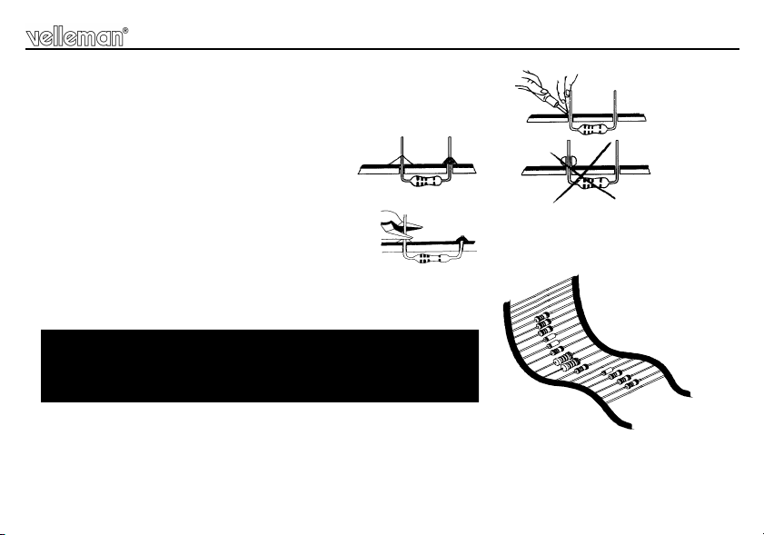
3. Resistors
R...
Construction
D1 : 1N4007
D2 : 1N4148
D3 : 1N4148
D4 : 1N4148
D5 : 1N4148
D6 : 1N4148
D7 : 1N4148
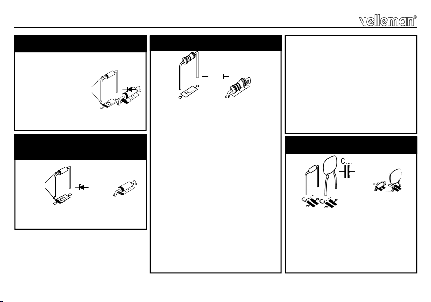
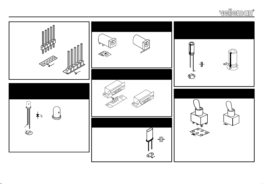
1. Diodes. Watch the polarity!
D...
CATHODE
C2 : 100nF (104, u1)
C3 : 100nF (104, u1)
C4 : 100nF (104, u1)
C6 : 18pF (18)
C7 : 18pF (18)
C8 : 100nF (104, u1)
4. Capacitors
ZD1 : 8V2
2. Zenerdiodes. Watch the
polarity!
ZD...
CATHODE
R21 : 680 (6 - 8 - 1 - B)
R22 : 680 (6 - 8 - 1 - B)
R23 : 680 (6 - 8 - 1 - B)
R24 : 680 (6 - 8 - 1 - B)
R25 : 10K (1 - 0 - 3 - B)
R26 : 10K (1 - 0 - 3 - B)
R27 : 10K (1 - 0 - 3 - B)
R28 : 10K (1 - 0 - 3 - B)
R29 : 1K (1 - 0 - 2 - B)
R30 : 10K (1 - 0 - 3 - B)
R31 : 3K3 (3 - 3 - 2 - B)

7
T1 : BC547
T2 : BC547
T3 : BC557
T4 : BC547
T5 : BC547
Construction
8. Transistors.
IC1 : 8P
IC2 : 14P
IC3 : 18P
IC4 : 28P
6. IC sockets, Watch the
position of the notch!
LD1 : 3mm
LD2 : 3mm
LD3 : 3mm
LD4 : 3mm RED
LD5: 3mm
LD6 : 3mm
LD8 : 3mm
LD7 : 3mm GREEN
7. LEDs. Watch the polarity !
COLOR= 2...5
LD...
CATHODE
VR1 : UA78L12
VR2 : UA78L05
9. Voltage regulator
SW1
SW2
SW3 KRS0611
SW4
SW6
5. Push buttons
VR...
JP1 : 2P
JP2 : 2P
JP3 : 2P
JP4 : 2P
JP5 : 2P
JP6 : 2P
10. Header

8
SK3 : 5P
C1 : 220µF
15. Electrolytic Capacitor.
Watch the polarity !
C...
Construction
LD9 : Blinking red (5mm)
LD1
CATHODE
11. Blinking LED. Watch the
polarity!
SK1 : 15VDC (Power)
12. DC - Jack
SK2 : RS232 (9p female)
13. Sub D - connector
X1 : 4MHz
X...
14. Quartz crystal
SW5 : 3 pos. / 2 pole
ON - OFF - ON
Run / Standby / Prog)
16. Switch

9
Mount the rubber feet on the solder side of
the PCB, see fig 1.0.
17. Rubber feet
Construction
• Place the Velleman® software CD in your CD-ROM player.
• Select ‘Browse through this CD for other Velleman software’ (this message will not be displayed on your screen
if ‘AUTORUN’ is not activated.
• Select the right folder on the CD with Windows Explorer).
• Select the ‘Velleman Kits’ folder. Select the ‘K8048’ folder.
• Run the ‘INSTALL_K8048.EXE’ program in the ‘\Velleman kits\K8048\’ folder.
• Follow the indications on the screen until all files are installed.
19. Software installation
*PIN 9 is not connected in K8076 !
Serial CABLE for K8048, K8076 and VM111
1
62
73
84
95
SK1
SUBD 9-POLE MALE
1
6
2
7
3
8
4
95
SK2
SUBD 9-POLE FEMALE
FIG 1.0
18. Serial cable

10
20. Schematic diagram.
Schematic diagram

11
PCB
21. PCB

5 410329 291952
Modifications and typographical errors reserved - © Velleman nv. H8048IP - 2004 - ED1 (rev. 5.0)
Other manuals for K8048
1
Table of contents
Other Velleman Motherboard manuals