Velocity T-4200 User manual

High Reliability, Rack-Space Saving,
Video and Audio Extension Solutions
T-4200 DVI Modules
KVM Extension Solution
Velocitykvm T-Series
Thinklogical LLC
100 Washington Street
Milford, Connecticut 06460 U.S.A.
Telephone: 1-203-647-8700
Fax: 1-203-783-9949
www.thinklogical.com
Extend Distribute Innovate
®
PRODUCT MANUAL

®
T-Series DVI Modules, Rev. A 2 September 2011
Extend Distribute Innovate
®
Copyright Notice
Copyright © 2011. All rights reserved. Printed in the U.S.A.
Thinklogical LLC
100 Washington Street
Milford, Connecticut 06460 U.S.A.
Telephone: 1-203-647-8700
All trademarks and service marks are property of their respective owners.
Subject: VelocityKVM T-Series DVI Modules Product Manual
Revision: A, September 2011

®
T-Series DVI Modules, Rev. A 3 September 2011
Table of Contents
PREFACE......................................................................................................................................................................4
Conventions Used in this Manual...............................................................................................................................4
1. SYSTEM FEATURES................................................................................................................................................5
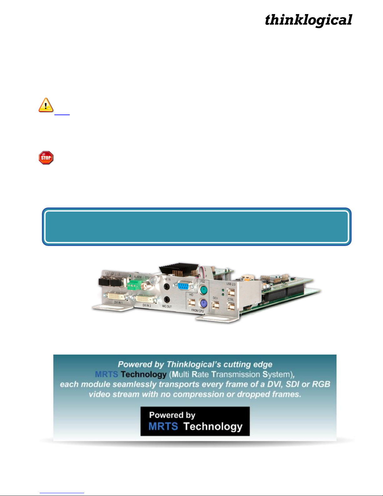
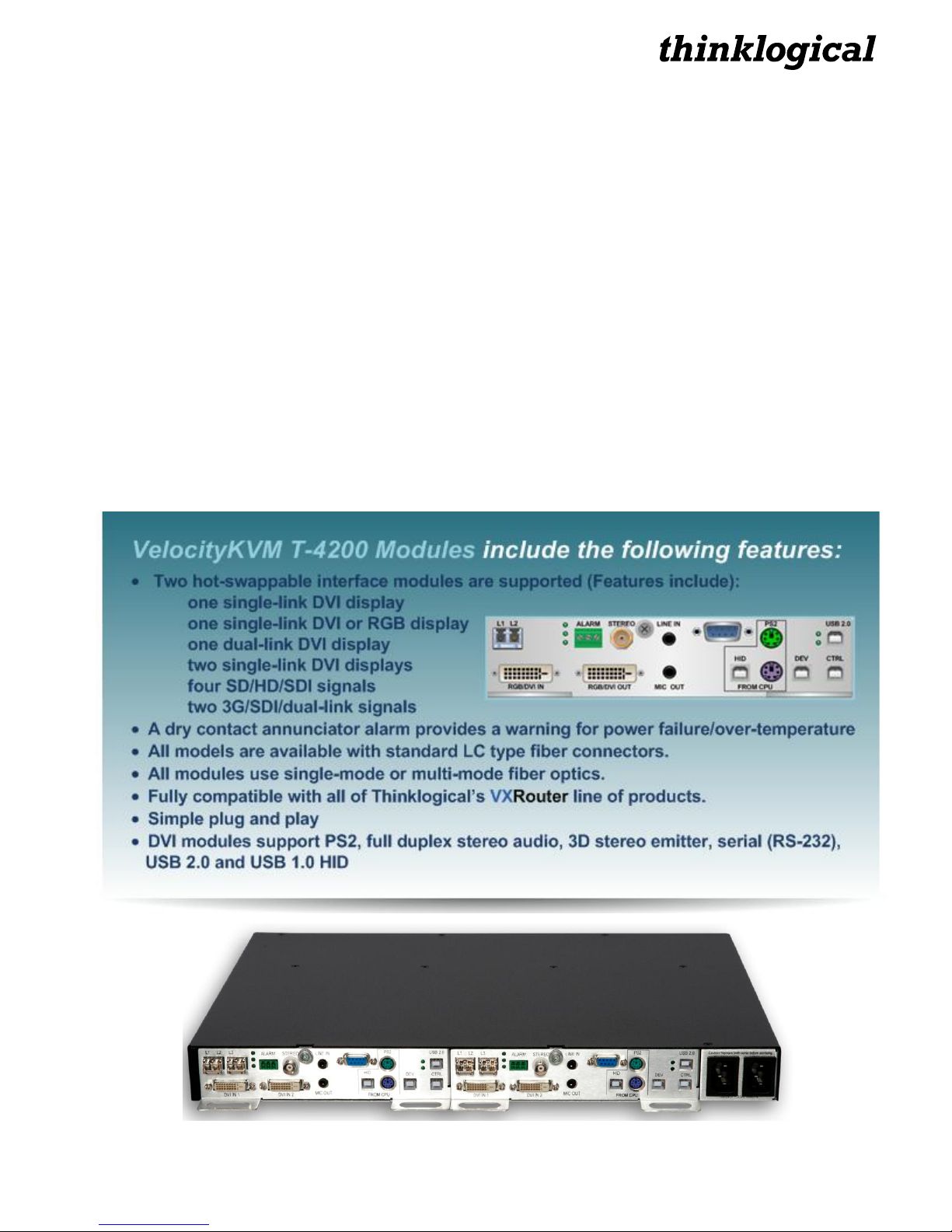
1.1 T-4200 Series DVI Modules..............................................................................................................................5
1.2 Contents............................................................................................................................................................6
1.2.1 Video Cables.............................................................................................................................................6
1.2.2 Peripheral cables......................................................................................................................................6
2. CONNECTING THE VelocityKVM T-SERIES EXTENDER......................................................................................7
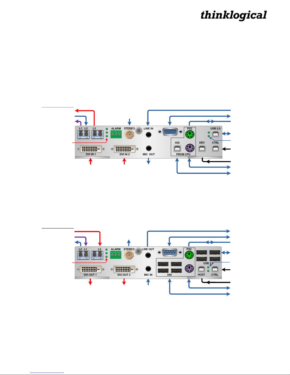
2.1 Transmitter Modules ........................................................................................................................................7
2.2 Receiver Modules..............................................................................................................................................7
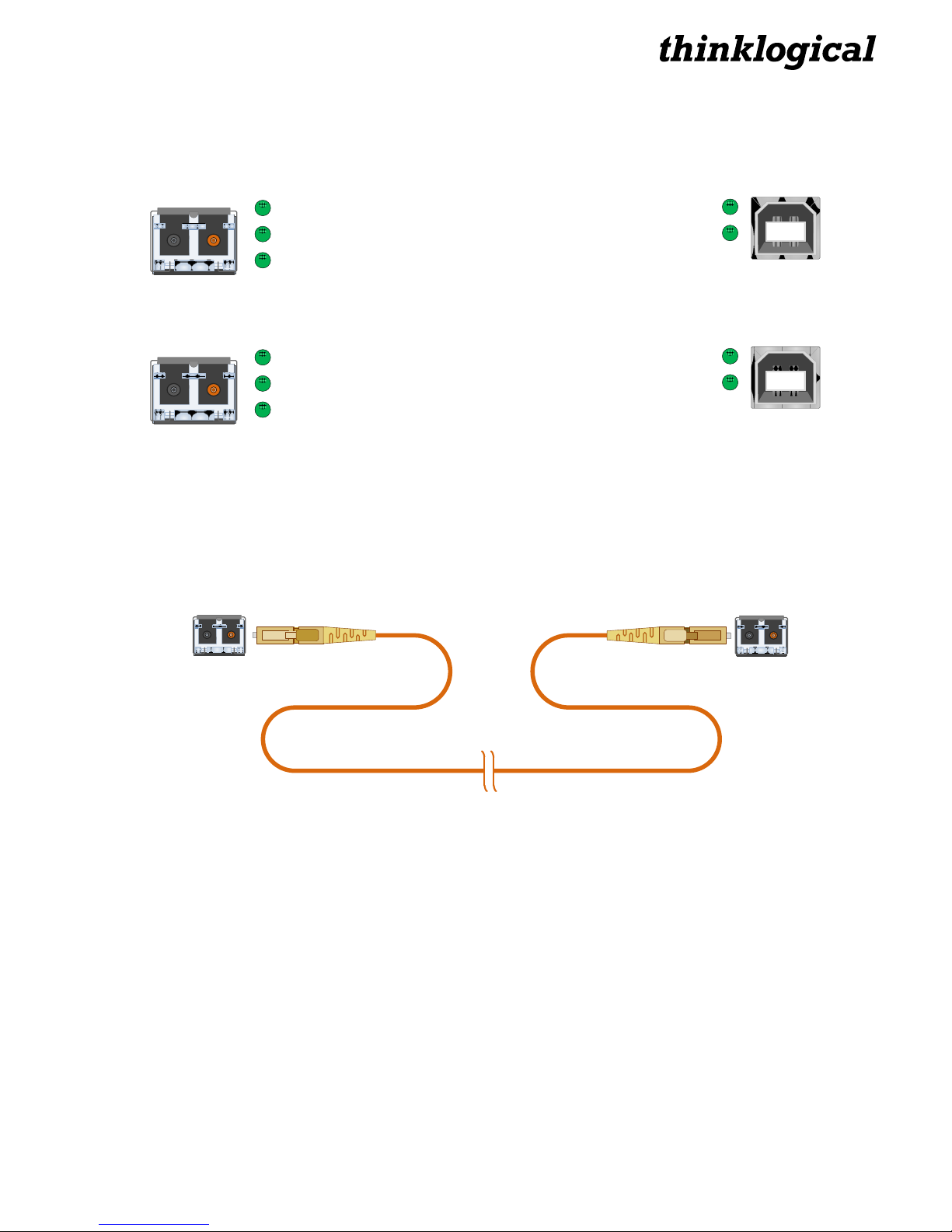
2.3 Module LEDs .....................................................................................................................................................8
2.4 Fiber Optic Cables ............................................................................................................................................8
2.5 Installation.........................................................................................................................................................8
2.5.1 Rear Panel Views......................................................................................................................................9
2.6 Set-Up ................................................................................................................................................................9
2.6.1 Dry Contact Alarm....................................................................................................................................9
2.6.2 Firmware Upgrades..................................................................................................................................9
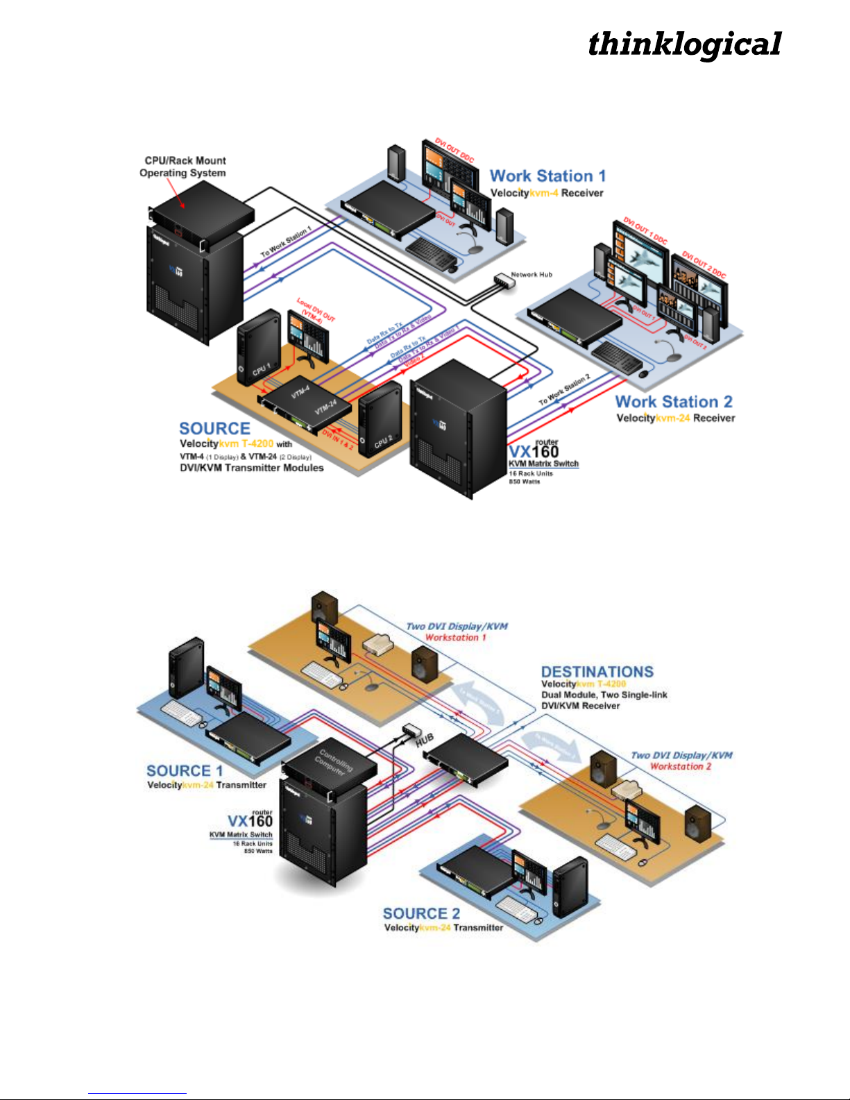
2.7 T-4200 Application Diagrams ........................................................................................................................10
2.7.1 VTM Transmitters to VelocityKVM Receivers (through 2 VX160 Routers)........................................10
2.7.2 VelocityKVM Transmitters to VTM Receivers (through a VX160 Router)..........................................10
2.7.3 Dual-Link DVI: VTM-8 Transmitters to VTM-8 Receivers (through 2 VX160 Routers) ......................11
2.7.4 T-4200 Transceiver Configuration (through a VX160 Router) ............................................................11
2.8 Technical Specifications................................................................................................................................12
3. REGULATORY & SAFETY COMPLIANCE............................................................................................................13
3.1 Safety Requirements......................................................................................................................................13
Symbols Found on the Product.................................................................................................................13
Regulatory Compliance..............................................................................................................................13
North America..............................................................................................................................................13
Australia & New Zealand ............................................................................................................................13
European Union...........................................................................................................................................13
Declaration of Conformity.....................................................................................................................13
Standards with Which Our Products Comply...........................................................................................14
3.2 Supplementary Information...........................................................................................................................14
3.2.1 Product Serial Number ..........................................................................................................................15
3.2.2 Connection to the Product ....................................................................................................................15
4. HOW TO CONTACT US..........................................................................................................................................15
4.1 Customer Support..........................................................................................................................................15
Website ........................................................................................................................................................16
Email.............................................................................................................................................................16
Telephone ....................................................................................................................................................16
Fax................................................................................................................................................................16
4.2 Product Support .............................................................................................................................................16
4.2.1 Warranty..................................................................................................................................................17
4.2.2 Return Authorization..............................................................................................................................17
Our Address ...............................................................................................................................................17
APPENDIX A: Quick Start Guides.............................................................................................................................18
A.1 VTM-24 Transmitters to VTM-24 Receivers (direct).....................................................................................18
A.2 VTM-4/VTM-24 Tx to VTM-4/VTM-24 Rx (through VX80 Router).................................................................19
A.3 VTM-4/VTM-8 Tx to Vel-4/Vel-8 Rx (through VX40 Router).........................................................................20
APPENDIX B: Thinklogical KVM Extenders- Theory of Operation ........................................................................21
APPENDIX C: VelocityKVM T-Series Ordering Information ...................................................................................22

®
T-Series DVI Modules, Rev. A 4 September 2011
PREFACE
Conventions Used in this Manual
As you use this manual you will notice certain conventions that bring your attention to important
information. These are Notes and Warnings. Examples are shown below.
Note: Important Notes appear in blue text preceded by a yellow exclamation point symbol,
like this.
A note is meant to call the reader’s attention to helpful information at a point in the text that is relevant
to the subject being discussed.
Warning! All Warnings appear in red text, followed by blue text, and preceded by a red
stop sign, like this.
A warning is meant to call the reader’s attention to critical information at a point in the text that is
relevant to the subject being discussed.
BEFORE STARTING ANY PROCEDURE, IT IS RECOMMENDED
THAT YOU READ THE INSTRUCTIONS THOROUGHLY!
The VelocityKVM T-4200 Series VTM-24 Transmitter Module

®
T-Series DVI Modules, Rev. A 5 September 2011
1.THE T-4200 SERIES DVI MODULES
The Logical Solution: Modular KVM Extension / DVI and SDI Support in One Unit
The VelocityKVM line of extenders continues to evolve and add value with exciting new capabilities. The
VelocityKVM T-4200 Series is housed in a high reliability, rack-space-saving chassis that includes all of
the same capabilities in a 1U device that used to require 2U. Featuring a dual interface and current
sharing power supplies, each 1U chassis supports two separate interface modules, allowing users to
combine module options within one chassis.
Available modules support a variety of video display options and all modules support PS2, full duplex
stereo audio, stereo emitter, serial (RS-232), USB 2.0 (up to 480 Mbps) and/or USB 1.0 HID.
Using multi-mode or single-mode fiber, the system allows users to securely locate a display device and
peripherals up to 40 kilometers away from the controlling computer without loss of resolution.
In addition, all high speed peripherals function with no latency, making it ideally suited for a wide range
of applications in the broadcast and post-production field, command and control centers, universities, air
traffic control, energy production and exploration, and most other commercial KVM applications.
1.1 T-Series Module Features

®
T-Series DVI Modules, Rev. A 6 September 2011
1.2 Contents
When you receive your Thinklogical®VelocityKVM T-Series Extender System, you should find the
following items:
VelocityKVM T-4200 Modular Chassis w/ dual Power Supply Modules
VelocityKVM T-Series Extender Module(s): Transmitter/Receiver/Transceiver
AC power cords, PWR-000006-R (International connections may differ) –Qty 2
VelocityKVM Extender Cables:
Video Cable, 2 Meters –See Technical Specifications, pg. 12
Audio Cable Kit (8 pcs.), 6 Feet, KIT-000005-R –Qty 1
VelocityKVM T-4200 Extender Product Manual CD
Product Quick Start Guide
1.2.1 Video Cables
Single-link: DVI-D Male Cable, 2 Meters (CBL000009-002MR)
DVI Male DVI Male
1.2.2 Peripheral Cables
KIT-000005-R Audio Cable Kit (8 pcs.)–Qty 1
2 each –6 pin mini din (6’)
2 each –USB A-B (6’)
2 each –3.5mm to 3.5mm plug (6’)
1 each –DB9M to DB9F (6’)
1 each –BNC male to male, 50 Ω(6’)

®
T-Series DVI Modules, Rev. A 7 September 2011
2.CONNECTING THE VelocityKVM T-4200 EXTENDER
All physical connections to the product use industry-standard connectors. Non-supplied cables are
commercially available. All connections are found on the rear of the unit.
2.1 Transmitter Modules
The Transmitter Module connects to the CPU (or other sources) using the supplied cables listed above.
The Transmitter then connects to the Receiver via multi-mode or single-mode fiber-optic cables. (See
paragraph 2.8 Technical Specifications on page 12, for details about specific optical distances using
various fiber types.)
USB 2.0 Port
Control Download
Device Download
PS2 Kybd. from CPU
USB HID Port
PS2 Mouse from CPU
RS-232 Serial Port (F)
Audio IN
Audio OUT
3D Stereo IN
DVI Video 2
IN
DVI Video 1
IN
L1: Video 1 & Data Tx to Rx
L2: Data Rx to Tx
L3: Video 2
VTM-24 Multi-Mode Transmitter
Fiber Optic Ports
Fiber Connection/
Alarm LEDs
USB 2.0 Link/Host
Indicator LEDs
2.2 Receiver Modules
The Receiver Module receives video and KVM data from the Transmitter via multi-mode or single-mode
fiber-optic cables. The Receiver’s output ports connect to the destination peripheral devices with their
own standard cables.
Host Download
PS2 to Keyboard
USB HID Ports (4)
Audio IN
DVI Video 2
OUT
DVI Video 1
OUT
L1: Video 1 & Data Tx to Rx
L2: Data Rx to Tx
L3: Video 2 3D Stereo
OUT
USB 2.0 Ports (4)
Control Download
PS2 to Mouse
RS-232 Serial Port (M)
Audio OUT
VTM-24 Multi-Mode Receiver
Fiber Optic Ports
Fiber Connection/
Alarm LEDs USB 2.0 Link/Device
Indicator LEDs

®
T-Series DVI Modules, Rev. A 8 September 2011
2.3 Module LEDs
Both the Transmitter and Receiver Modules feature five LEDs. Their functions are as follows:
Transmitter LEDs
L2 Fiber Connected
Non-functioning
Alarm Condition (flashing)
USB 2.0 Link Established
Host Communication established
USB 2.0
L3
Receiver LEDs
L1 Fiber Connected
Alarm Condition (flashing)
USB 2.0 Link Established
Device Communication established
CTRL
L3
L3 Fiber Connected
2.4 Fiber Optic Cable
Fiber optic cables connect the Transmitters to the Receivers. Standard multi-mode fiber optic cables
must be 50 or 62.5 microns, terminated with LC type fiber optic connectors. Be careful not to kink or
pinch the fiber optic cable as it is being installed and keep all bend radii to no less than 3 inches
(76.2mm).
Standard multi-mode fiber optic cable (up to 1000 meters),
50 or 62.5 microns, terminated with LC-type connectors
◄Transmit◄Receive
With two fibers connected (in models with one SFP) or with three fibers connected (in models with two
SFPs) video information is transmitted from the TX to the RX over fiber L1 (and L3 in models with two
SFPs). Fiber L2 is used as a data return path from the RX to the TX, allowing full duplex, bi-directional
RS-232 data transfer.
2.5 Installation
All physical connections to the product use industry-standard connectors. Non-supplied cables are
commercially available. All connections are found on the rear of the unit.

®
T-Series DVI Modules, Rev. A 9 September 2011
2.5.1 Rear Panel Views
T-4200 as a Transciever (Single-Link, 1 DVI Display)
VTM-4 Tx VTM-4 Rx
T-4200 as 2 Receivers (Dual-Link DVI & Single-Link RGB Displays)
VTM-5 RxVTM-8 Rx
VTM-24 Tx VTM-24 Rx
T-4200 as a Transceiver (Single-Link, 2 DVI Displays)
T-4200 as 2 Transmitters (Dual-Link DVI & Single-Link RGB Displays)
VTM-5 TxVTM-8 Tx
A selection of Velocity T-4200 Rear Panels in Transceiver, Receiver & Transmitter Configurations
2.6 Set-Up
2.6.1 Dry Contact Alarm
Dry contact alarms are located on the transmitter and receiver units. When there is an alarm condition
the relay is energized. An example of possible alarm causes might be over-temperature or a power
supply issue.
NORMALLY CLOSED NORMALLY OPEN
COMMON
ALARM
The dry contact alarm is a Form C contact with the following ratings:
Nominal Switching Capacity:1 A 30 VDC, 0.3 A 125 VAX (resistive load)
Max. Switching Power: 30 W (DC), 37.5 VA (AC) (resistive load)
2.6.2 Firmware Upgrades
Firmware upgrades are available through Thinklogical. Please call for technical assistance at:
1-203-647-8700.

®
T-Series DVI Modules, Rev. A 10 September 2011
2.7 T-4200 Application Diagrams
2.7.1Two Source Computers connected to one VelocityKVM T-4200 Chassis equipped with one VTM-4 TX and
one VTM-24 TX, which extends video and peripheral signals to two separate VelocityKVM (stand alone)
Receivers (VelocityKVM-4 and VelocityKVM-24) at two separate workstations. Signals are routed through two
Thinklogical VX160 Routers
2.7.2 Two Source Computers, each connected to a VelocityKVM-24 (stand alone) Transmitter extending video
and peripheral signals to one VelocityKVM T-4200 Chassis equipped with two VTM-24 RX Modules. The VTM-
24s extend to two separate workstations. Signals are routed through a Thinklogical VX160 Router.

®
T-Series DVI Modules, Rev. A 11 September 2011
2.7.3 Two Source Computers, each connected to a VTM-8 Dual-Link DVI Transmitter extending dual-link video
and peripheral signals to two VelocityKVM-8 Dual-Link DVI Receiver workstations. Signals are routed through
two Thinklogical VX160 Routers.
2.7.4 Two Source Computers, located at separate workstations, connected to one VelocityKVM T-4200
Transceiver Chassis equipped with dual VTM-24 Modules (one TX and one RX), which extends video and
peripheral signals to two separate VelocityKVM-24 (stand alone) destinations (one TX and one RX) at separate
workstations. Signals are routed through a Thinklogical VX160 Router.

®
T-Series DVI Modules, Rev. A 12 September 2011
2.8 Technical Specifications
Each Thinklogical VelocityKVM T-Series Module is designed to the following specifications:
Copper Connectors
Transmitter:
Video (2) DVI-D
Audio MIC/Line 3.5mm Jack
Serial Port DB9 Female
USB 2.0 USB B
PS2 Keyboard MiniDIN 6 Female
PS2 Mouse MiniDIN 6 Female
Firmware Updates USB B (3)
Fiber Connectors LC
Receiver:
Video (2) DVI-D
Audio MIC/Line 3.5mm Jack
Serial Port DB9 Male
USB 1.1 USB A (4)
USB 2.0 USB A (4)
PS2 Keyboard MiniDIN 6 Female
PS2 Mouse MiniDIN 6 Female
Firmware Updates USB B
Fiber Connectors LC
Optical Cable
Fiber Type: 50 or 62.5 micron, Multi-mode
Required (per module): 2 or 3, depending upon application. (Not supplied)
Optical Distance
Up to 65 meters with Type OM1
Up to 350 meters with Type OM2
Up to 650 meters with Type OM3
Up to 1000 meters with Type OM4
Operating Temp
and Humidity
0° to 50°C (32° to 122 °F), 5% to 95% RH, non-condensing
Dimensions
Height: 1.65” (41.91 mm) ± .039”; .1 mm
Depth: 6.366” (161.70 mm)* ± .039”; .1 mm
Width: 3.693” (93.80 mm) ± .039”; .1 mm
Supply Voltage
100-240 VAC, 47-63 Hz, Universal AC power supply
Power Consumption
10 Watts per module
Compliance
Approvals for US, Canada, and European Union
Warranty
Twelve months from date of purchase. Extended warranties available.

®
T-Series DVI Modules, Rev. A 13 September 2011
3. REGULATORY & SAFETY COMPLIANCE
3.1 Safety Requirements
3.1.1 Symbols found on the product
Markings and labels on the product follow industry-standard conventions. Regulatory markings found on
the products comply with domestic and many international requirements.
All T-4200 DVIModules are
designed and identified as
Class 1 LASER products
.
CLASS 1 LASERS do not require any special
precautions under conditions of normal use.
3.1.2 Regulatory Compliance
Thinklogical VelocityKVM Extender products are designed and made in the U.S.A. VelocityKVM
Extender products have been tested by a certified testing laboratory and found to be fully compliant with
the following standards (both domestic USA and many international locations):
North America
Safety
ANSI/UL60950-1: 1
st
Edition (2003)
CAN/CSA C22.2 No. 60950-1-03
LASER Safety
CDRH 21CFR 1040.10
Class 1 LASER Product
Electromagnetic Interference
FCC CFR47, Part 15, Class A
Industry Canada ICES-003 Issue 2, Revision 1
Australia & New Zealand
This is a Class A product. In a domestic environment this product may cause radio interference, in
which case the user may be required to take adequate measures.
European Union
Declaration of Conformity
Manufacturer’s Name & Address: Thinklogical®
100 Washington Street
Milford, Connecticut 06460 USA
Telephone 1-203-647-8700
These products comply with the requirements of the Low Voltage Directive 72/23/EEC and the EMC
Directive 89/336/EEC.

®
T-Series DVI Modules, Rev. A 14 September 2011
3.1.3 Standards with Which Our Products Comply
Safety
CENELEC EN 60950-1, 1
st
Edition (2001)
LASER Safety
IEC60825:2001 Parts 1 and 2
Class 1 LASER Product
Electromagnetic Emissions
EN55022: 1994 (IEC/CSPIR22: 1993)
EN61000-3-2/A14: 2000
EN61000-3-3: 1994
Electromagnetic Immunity
EN55024: 1998 Information Technology Equipment-Immunity Characteristics
EN61000-4-2: 1995 Electro-Static Discharge Test
EN61000-4-3: 1996 Radiated Immunity Field Test
EN61000-4-4: 1995 Electrical Fast Transient Test
EN61000-4-5: 1995 Power Supply Surge Test
EN61000-4-6: 1996 Conducted Immunity Test
EN61000-4-8: 1993 Magnetic Field Test
EN61000-4-11: 1994 Voltage Dips & Interrupts Test
3.2 Supplementary Information
The following statements may be appropriate for certain geographical regions and might not apply to
your location.
This Class A digital apparatus meets all requirements of the Canadian Interference-Causing
Equipment Regulations.
Cet appareil numérique de la classe A respecte toutes les exigencies du Règlement sur le matérial
brouilleur du Canada.
Warning! This is a Class A product. In a domestic environment, this product may
cause radio interference, in which case the user may be required to take corrective
measures.

®
T-Series DVI Modules, Rev. A 15 September 2011
Note: This equipment has been tested and found to comply with the limits for a
Class A digital device, pursuant to part 15 of the FCC Rules. These limits are designed to
provide reasonable protection against harmful interference when the equipment is
operated in a commercial environment. This equipment generates, uses and can radiate
radio frequency energy and, if not installed and used in accordance with the instruction
manual, may cause harmful interference to radio communications in which case the user
may be required to take adequate corrective measures at their own expense.
Note: This Class A digital apparatus complies with Canadian ICES-003 and has been
verified as being compliant within the Class A limits of the FCC Radio Frequency Device
Rules (FCC Title 47, Part 15, Subpart B CLASS A), measured to CISPR 22: 1993 limits and
methods of measurement of Radio Disturbance Characteristics of Information
Technology Equipment.
Note:
The user may notice degraded audio performance in the presence of
electromagnetic fields
.
Note:
If using a keyboard that is noise susceptible, a ferrite ring on the keyboard
cable may be needed to comply with Immunity Requirements
3.2.1 Product Serial Number
The VelocityKVM products have a unique serial number, imprinted on an adhesive label that is fixed to
the bottom of the chassis. The serial number includes a date-code. The format for the date-code is 2
digits for the month, 2 digits for the day and 2 digits for the year, plus two or three digits for a unique unit
number. This serial number is also found on the original shipping carton.
3.2.2 Connection to the Product
Connections and installation hardware for our products use industry-standard devices and methods. All
wiring connections to the customer equipment are designed to minimize proprietary or customized
connectors and cabling. Power connections are made with regionally appropriate power cords and
approved methods.
4..HOW TO CONTACT US
4.1 Customer Support
Thank you for choosing Thinklogical® products for your application.
We appreciate your business and are dedicated to helping you successfully use our products.
is always here to help you.
To contact us, please use the following telephone numbers and internet-based methods:
®

®
T-Series DVI Modules, Rev. A 16 September 2011
Thinklogical is an engineering company and you will receive the information you require directly from our
most knowledgeable engineers. We believe that the first lines of support are the design engineers that
developed each product. Therefore, your questions will be handled promptly by our in-house engineers
who are most familiar with your products.
To contact Thinklogical, use the following telephone numbers and internet-based methods:
Website
Visit our website for specific product information, current updates and our complete line of products at
www.thinklogical.com.
Our internet website offers product information on all current systems, including technical specification
sheets and installation guides (for viewing online or for download), product diagrams showing physical
connections and other helpful information.
Note: Most online documents are stored as Adobe Acrobat “PDF” files. If you do not have
the Adobe Acrobat reader needed to view PDF files, visit www.adobe.com for a download.
Email
Thinklogical is staffed Monday through Friday from 8:30am to 5:00pm, Eastern Time Zone. We will
make every effort to respond to your email inquiries promptly. Please use the following email addresses
for any of your concerns:
info@thinklogical.com –Information on Thinklogical and our products.
sales@thinklogical.com –Sales Department - orders, questions or issues.
support@thinklogical.com –Product support, technical issues or questions, product
repairs and request for Return Authorization.
Telephone
Telephone Sales: Contact our expert sales staff via telephone in Milford, CT at 1-203-647-8700 or if in
the continental US, you may use our toll-free number 1-800-291-3211. We are here Monday through
Friday from 8:30am to 5:00pm, Eastern Time Zone. Ask for your representative’s direct dial phone
number when you call.
Telephone Product Support: Contact Product Support via telephone in Milford, CT at 1-203-647-8700.
The support lines are manned Monday through Friday, 8:30am to 5:00pm, Eastern Time Zone.
International Sales: Please contact our US sales staff in Milford, CT at 1-203-647-8700. We are here
Monday through Friday, 8:30am to 5:00pm, Eastern Time Zone (same as New York City). If leaving a
voice message please provide a “best time to call back” so we may reach you at your convenience.
Our switchboard attendant will direct your call during regular business hours. We have an automated
attendant answering our main telephone switchboard after regular business hours and holidays. You
can leave voice messages for individuals at any time. Our Sales Representatives have direct numbers
to speed up your next call to us.
Fax
Our company facsimile number is 1-203-783-9949. Please indicate the nature of the fax on your cover
sheet and provide return contact information.

®
T-Series DVI Modules, Rev. A 17 September 2011
4.2 Product Support
Thinklogical’s support personnel are available Monday through Friday from 8:30am to 5:00pm,
Eastern Time Zone. If your application requires assistance at some time outside of our normal business
hours, please contact us beforehand and we will do our best to make arrangements to help you with your
Thinklogical products.
4.2.1 Warranty
Thinklogical®warrants this product against defects in materials and workmanship for a period of one
year from the date of delivery. Thinklogical®and its suppliers disclaim any and all other warranties.
Note: Thinklogical Inc. products carry a one year warranty, with longer term available at
time of purchase on most products. Please refer to your product invoice for your products
Warranty Terms & Conditions.
Defect remedy shall be the repair or replacement of the product, provided that the defective product is
returned to the authorized dealer within a year from the date of delivery.
If you wish to return your device, contact the Thinklogical authorized dealer where you purchased the
device, or if you purchased directly, call Thinklogical at 1-800-291-3211 (USA).
4.2.2 Return Authorization
In the event you must return a product to Thinklogical directly:
Contact Customer Support at 1-800-291-3211 or 1-203-647-8700.
Customer Support will ask you to describe the problem and will issue you a Return Merchandise
Authorization number (RMA#). If possible, pack the device in its original box and return it with the
RMA# printed clearly on the box.
Return address for products with a Return Material Authorization:
Thinklogical® LLC
Attn: RMA#
100 Washington Street
Milford, CT 06460 USA
Phone: 1-800-291-3211 (USA only)
Note: DO NOT return a product to Thinklogical without a Return Material Authorization.
Our Address
If you have any issue with a product, have product questions or need technical assistance with your
Thinklogical system, please call us at 1-800-291-3211 (USA only) or 1-203-647-8700 and let us help. If
you’d like to write us, our mailing address is:
Thinklogical®LLC
100 Washington Street
Milford, CT 06460 USA

®
T-Series DVI Modules, Rev. A 18 September 2011
Appendix A- Quick Start Guides
A.1 VTM-24 Transmitters to VTM-24 Receivers (direct)
USB 2.0
HOST CTRL
LINE OUTSTEREO
ALARM
DVI OUT 2
DVI OUT 1
L2 L1 L3
MIC IN HID
PS2
USB 2.0
HOST CTRL
LINE OUTSTEREO
ALARM
DVI OUT 2
DVI OUT 1
L2 L1 L3
MIC IN HID
PS2
110-240V ~, 0.5A, 50/60 Hz
Caution! Remove both cords before servicing
VTM-24 RX MODULE 1
DVI OUT 1
77
QUICK START GUIDE
Manual_T-4200_QSG_VTM-24 TX_to_VTM-24 RX
Extend Distribute Innovate
As used with Thinklogical’s Velocitykvm T-4200 Receiver and Velocitykvm T-4200 Transmitter
6
DVI OUT 2
PS/2 or USB
HID connectors
USB 2.0
STEP 5/STEP 5:Connect the DVI IN cables from the Source
CPUs to VelocityKVM Transmitter Module 1 and Module 2.
6
1
STEP 3/STEP 3:Depending on your
receiver’s configuration, connect your
peripheral devices to the VelocityKVM T-
4200 Receiver Module 1 and Receiver
Module 2 using standard cables, as
shown. Turn all the devices ON. 33STEP 2/STEP 2:On the front of the Receiver
chassis, ensure that the Right and Left Power Supply
Module ON/OFF Switches are in the OFF (0)
position. Install the Right Power Supply Module AC
Power Cord (Left receptacle) and the Left Power
Supply Module AC Power Cord (Right receptacle)
and plug them into standard AC sources. On the
front of the chassis, turn ON the Right and Left
Power Supply Module ON/OFF Switches.
4
4
PS2 Mouse
PS2 Keyboard
Audio OUT
Audio IN
HID USB
DVI OUT 1
DVI OUT 2
PS2 Mouse
PS2 Keyboard
Audio OUT
Audio IN
HID USB
DVI OUT 1
DVI OUT 2
110-240V ~, 0.5A, 50/60 Hz
Caution! Remove both cords before servicing
FROM CPU
PS2 USB 2.0
DEV CTRL
HID
MIC OUT
LINE IN
STEREO
ALARM
DVI IN 2
DVI IN 1
L1 L2 L3
FROM CPU
PS2 USB 2.0
DEV CTRL
HID
MIC OUT
LINE IN
STEREO
ALARM
DVI IN 2
DVI IN 1
L1 L2 L3
2
2
Transmitter
DVI OUT 2
DVI OUT 1
PS/2 or USB
HID connectors
USB 2.0
VTM-24 TX MODULE 1
VTM-24 RX MODULE 2
VTM-24 TX MODULE 2
L3L1L2L3L1L2
VTM-U00M24-LCTX
Velocitykvm T-4200
Receiver
VTM-U00M24-LCRX
Velocitykvm T-4200
Source CPU to
Transmitter
Module 1
Source CPU to
Transmitter
Module 2
1
STEP 1/STEP 1:Connect your VelocityKVM T-
4200 Receiver Module 1 to Transmitter
Module 1 and Receiver Module 2 to
Transmitter Module 2 using multi-mode fiber-
optic cables (up to 1000 meters). Connect L1 to
L1 (Data Tx to Rx & Video 1), L2 to L2 (Data
Rx to Tx) and L3 to L3 (Video 2).
STEP 4/STEP 4:On the
front of the Transmitter
chassis, ensure that the
Right and Left Power
Supply Module ON/OFF
Switches are in the OFF
(0) position. Install the
Right Power Supply
Module AC Power Cord
(Left receptacle) and the
Left Power Supply
Module AC Power Cord
(Right receptacle) and
plug them into standard
AC sources. On the
front of the chassis, turn
ON the Right and Left
Power Supply Module
ON/OFF Switches.
STEP 6/STEP 6:Connect the PS2, USB and Audio cables from the
Source CPUs to VelocityKVM Transmitter Module 1 and Module 2.
55
STEP 7/STEP 7:Turn ON both Source CPUs. Ensure that all system
functions are operating properly.

®
T-Series DVI Modules, Rev. A 19 September 2011
A.2 VTM-4/VTM-24 Tx to VTM-4/VTM-24 Rx (through VX80 Router)
Local
DVI OUT
Module 1 DVI OUT 1
(DDC)
Module 1
DVI OUT 1
Module 2
DVI IN 1
Module 2
DVI IN
Module 1
Source
CPU 1
L1: Data TX to RX and Video
L2: Data RX to TX
External Control CPU
Network Hub
STEP 8: Connect the Controller
Cards’ LAN Ports to your Controller
CPU with CAT5 cables.
(CPU IP address: 192.168.13.9)
8
Optional Secondary Controller Card
IP address: 192.168.13.16
Primary Controller Card
IP Address: 192.168.13.15
QUICK-START GUIDE
QUICK-START GUIDE
As used with Thinklogical’s
T-4200 Video Extension System STEP 1: Connect your VTM Receiver Modules to the
VX80 using multi-mode fiber-optic cables (up to 1000
meters). Connect L1 to any Transmit Port and L2 to
the same numbered Receive Port. Connect L3 to any
other Transmit Port.
STEP 2: Install the Right Power Supply Module AC
Power Cord (Left receptacle) and the Left Power
Supply Module AC Power Cord (Right receptacle).
Plug both Receiver AC Cords into a standard AC
source. On the front of the chassis, turn ON the Right
and Left Power Supply Modules.
2
3STEP 3: For each module,
connect a monitor to each of
the DVI OUT ports with a
standard DVI cable. Connect
the required peripheral
devices with standard copper
cables and turn them all ON.
STEP 4: Connect your VTM Transmitter Modules to the VX80
using multi-mode fiber-optic cables (up to 1000 meters).
Connect L1 to any Receive Port and L2 to the same numbered
Transmit Port. Connect L3 to any other Receive Port.
4
5
STEP 5: Ensure the Power Supply Switches on the front panel are in the OFF position. Install the
Right Power Supply Module AC Power Cord (Left receptacle) and the Left Power Supply
Module AC Power Cord (Right receptacle). Plug both Transmitter AC Cords into a standard AC
source. Turn ON the Right and Left Power Supply Modules.
STEP 6: Connect the DVI IN cables from the Source CPUs to the DVI IN ports of each
Transmitter Module. If desired, connect a local monitor to the Vel-3 Transmitters’ DVI OUT port
with a standard DVI cable. Connect the peripheral devices from the CPU to the Transmitters with
standard copper cables. Ensure the CPU is turned ON.
STEP 7: If stereo 3-D molecular visualization on your desktop is desired, connect the Stereo OUT
from the CPU to the Transmitter Module’s STEREO INPUT. Connect a 3-D Active Stereo Emitter
to the STEREO OUT receptacle on the Receive module.
STEP 9: Connect both supplied AC Power Cords (PWR-
0000006-R) to the receptacles located on the VX80's
power supplies. Plug each one into a standard AC source.
Verify that all system functions are operating properly.
VTM-4_VTM-24_VX80_QSG_Manual
VTM-4 Transmitter Module
VTM-U00004-LCTX
KVM Matrix Switch
Powered by
MRTS Technology
VX80
router
To LAN Ports
Stereo Emitter OUT
Mod. 1
Stereo 3-D
◄Audio IN
Audio OUT►
USB
DVI IN 2 Module 2
PS2 Mouse
PS2 Keyboard
◄Audio IN
Audio OUT►
USB
PS2 Mouse
PS2 Keyboard
Stereo 3-D
Source CPU 2
DVI OUT 2
Module 1 DVI OUT 2
Module 2
Stereo Emitter OUT
Mod. 2
VTM-4 Receiver Module
VTM-U00004-LCRX
1
Keyboard
and Mouse to
PS2 or USB
HID Ports
Keyboard
and Mouse to
PS2 or USB
HID Ports
L1: Data TX to RX and Video 1
L2: Data RX to TX
L3: Video 2
6
77
7
7
With VTM-4 and VTM-24 Transmitter and Receiver Modules
VTM-24 Transmitter Module
VTM-U00024-LCTX VTM-24 Receiver Module
VTM-U00024-LCRX
9

®
T-Series DVI Modules, Rev. A 20 September 2011
A.3 VTM-4/VTM-8 Tx to VTM-4/VTM-8 Rx (through VX40 Router)
Local
DVI OUT
Module 1
DVI IN
Dual-Link
Module 2
DVI IN
Module 1
Source CPU 1
Network Hub
STEP 8: Connect the VX40 Controller Cards’
LAN Ports to your Controller CPU with CAT5
cables.
(CPU IP address: 192.168.13.9)
Optional Secondary Controller Card
IP address: 192.168.13.16
Primary Controller Card
IP Address: 192.168.13.15
STEP 1: Connect your VelocityKVM Single-Link and Dual-Link Receivers to
the VX40 using multi-mode fiber-optic cables (up to 1000 meters). Connect L1
to any Transmit Port and L2 to the same numbered Receive Port. Connect the
VelocityKVM-8 Receiver’s L3 to any other Transmit Port.
STEP 2: Ensure that each VelocityKVM Receiver’s ON/OFF switch is in the
OFF (0) position. Insert the AC power cord into the Receiver and plug it into a
standard AC source. Turn the unit ON.
STEP 3: Depending on your configuration, connect your peripheral devices
(monitors, keyboard, mouse, etc.) to the VelocityKVM Receivers using
standard cables as shown in the examples below. Turn all the devices ON.
STEP 4: Connect your VTM Transmitter Modules to the VX40
using multi-mode fiber-optic cables (up to 1000 meters).
Connect L1 to any Receive Port and L2 to the same numbered
Transmit Port. Connect VTM-8's L3 to any other Receive Port.
STEP 5: Install the Right Power Supply Module AC Power Cord (Left receptacle) and
the Left Power Supply Module AC Power Cord (Right receptacle). Plug both
Transmitter AC Cords into a standard AC source. On the front of the chassis, turn ON
the Right and Left Power Supply Modules.
STEP 6: Connect the DVI IN cables from the Source CPUs to the DVI IN ports of each
Transmitter Module. If desired, connect a local monitor to the Transmitters’ DVI OUT
port with a DVI cable. Connect the peripheral devices from the CPU to the
Transmitters with standard copper cables. Ensure the CPUs are turned ON.
STEP 7: If stereo 3-D molecular visualization is desired, connect the Stereo OUT
from the CPU to the Transmitter Module’s STEREO INPUT. Connect a 3-D Active
Stereo Emitter to the STEREO OUT receptacle on the Receive.
STEP 9: Connect both supplied AC Power Cords (PWR-
0000006-R) to the receptacles located on the VX40's
power supplies. Plug each one into a standard AC source.
Verify that all system functions are operating properly.
VTM-4Tx_VTM-8Tx_VX40_Vel-4Rx_Vel-8Rx_QSG_Manual
VTM-4 Transmitter
(Module 1)
VTM-U00004-LCTX
Powered by
MRTS Technology
To LAN Ports
Stereo 3-D
◄Audio IN
Audio OUT►
USB HID
PS2 Mouse
PS2 Keyboard
◄Audio IN
Audio OUT►
USB HID
PS2 Mouse
PS2 Keyboard
Stereo 3-D
Source CPU 2
Stereo Emitter OUT
VelocityKVM-4
Receiver 1
VEL-U00M04-LCRX
1
Keyboard and Mouse to
PS2 or USB HID Ports
L1: Data TX to RX and Video Primary
L2: Data RX to TX
L3: Video Secondary
VTM-8 Transmitter
(Module 2)
VTM-U00008-LCTX
Local
DVI OUT Dual-
Link Module 2
External Control CPU
Keyboard and Mouse to
PS2 or USB HID Ports
DVI OUT (DDC)
Rx 1 DVI OUT
Rx 1
DVI OUT (DDC)
Dual-Link Rx 2
DVI OUT
Dual-Link Rx 2
Stereo Emitter OUT
USB 2.0 OUT
USB 2.0 OUT
VelocityKVM-8
Receiver 2
VEL-U00M08-LCRX
1
2
2
3
3
4
5
66
778
9
7
7
Complete steps 1 through 9 to connect to the VX40 KVM Matrix Switch
L1: Data TX to RX and Video
L2: Data RX to TX
T-4200
VTS-004200
VX40 Router KVM Matrix Switch Chassis, 6 Rack Units, 400 Watts
QUICK-START GUIDE
QUICK-START GUIDE
As used with Thinklogical’s®T-4200
Video Extension System
As used with Thinklogical’s®T-4200
Video Extension System
With VTM Transmitter Modules and VelocityKVM Receivers
KVM Matrix Switch
VX40
router
Table of contents