MA-VE-RIVC-00-04 Manual vela receiver rev4 eng Rev.4 Page 3 of 4
USER MANUAL
RECEIVER PROGRAMMING AND OUTPUT CONFIGURATION
All programming operations of receiver and outputs configuration are made by the same button.
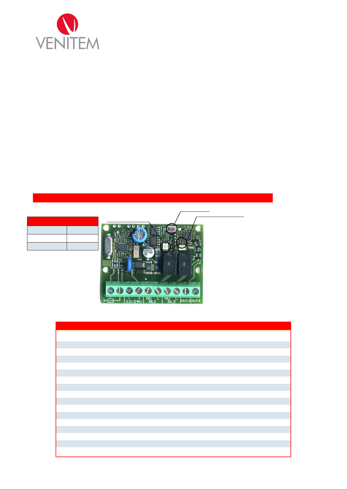
The two bicolor LEDs (green, red, red-green) give the information on different programming and configuration
phases.
LED 1 is located at the left side of LED 2 ; each LED gives the indications on output state:
LED 1 green: carried out operations refer to terminal RL1;
LED 1 red: carried out operations refer to terminal RL2;
LED 2 green: carried out operations refer to terminal OUT3;
LED 2 red: carried out operations refer to terminal OUT4;
ACQUISITION AND REMOVAL
By the acquisition procedure the transmitters that actualize the output of receiver are memorized
By the removal procedure the desired transmitter or all transmitters are removed from memory of receiver.
To start the acquisition and removal mode.
For switching from an option to another push and release the button.
1st push: LED 1 is green. Acquiring phase of a transmitter on RL1;
2nd push: LED 1 is red. Acquiring phase of a transmitter on RL2;
3rd push: LED 2 is green. Acquiring phase of a transmitter on OUT3;
4th push: LED 2 is red. Acquiring phase of a transmitter on OUT4;
5th push: LED 1 blinks with red-green color. Removal phase of a transmitter from memory.
When the button is released the receiver remains in the selected option for 5 seconds. After they have expired, the
receiver exits the selected mode; if during these 5 seconds it receives a valid code, a signal of correct
memorization or removal is given by LEDs switching-off for 0,5 seconds.
When a transmitter is memorized or removed, 5 more seconds are available for a further memorization or removal.
Exemple 1: memorization of transmitter on relay 1:
Push and release the button: LED 1 turns on green;
within 5 seconds generate a signal for memorizing the desired transmitter;
LED turns off for 0,5 seconds to confirm the acquisition;
Wait for 5 seconds (or push again the button and release it) so that the receiver exits from acquiring
mode: the return to operating mode is signaled by LED switching-off.
Exemple 2: memorization of transmitter on OUT4:
Push the button 4 times: at first pressure LED 1 switches on green, at second pressure LED 1 switches
on red, at third LED 2 switches on green, at fourth LED 2 switches on red;
LED turns off for 0,5 seconds to confirm the acquisition;
Wait for 5 seconds (or push again the button and release it) so that the receiver exits from acquiring
mode: the return to operating mode is signaled by LED switching-off.
Exemple 3: removal of transmitter from memory:
Push the button 5 times: at first pressure LED 1 switches on green, at second pressure LED 1 switches
on red, at third LED 2 switches on green, at fourth LED 2 switches on red; at fifth pressure LED 1 blinks in red-
green.
within 5 seconds generate a signal for remove the desired transmitter;
LED turns off for 0,5 seconds to confirm the removal (if transmitter wasn’t previously acquired, removal is
not signaled);
Wait for 5 seconds (or push again the button and release it) so that the receiver exits from acquiring
mode: the return to operating mode is signaled by LED switching-off.
SETTING OF OUTPUTS
All outputs can be settled on following modes
MONOSTABLE mode: at reception of code the output stays active during reception of it;
BISTABLE mode: at reception of code the output activates if previously it was deactivated and vice versa;
TEMPORIZED mode: at reception of code the output activates for a presetted time. Note: for deactivating
the output, push again the button of transmitter after at least 5 seconds from activation.
Selecting a working mode
To enter the setting mode of outputs it is necessary to keep pushed the button during acquiring phase until the
LED of chosen output for mode change, start to blink.
Exemples:
Setting of relay 1: push and keep pushing the button. LED 1 switches on green. After 3 seconds from
pressure of button, LED 1 green starts to blink quickly: setting mode MONOSTABLE.
Setting of OUT3: push and release the button. LED 1 switches on green. Push the button a second time
and release it: LED 1 switches on red. Push the button a third time and keep pushing: LED 2 switches on green.
After 3 seconds from pressure of button, LED 2 green starts to blink quickly to signal MONOSTABLE mode.
After 5 seconds without pushing the button LED blinks slowly to signal MONOSTABILE mode.