Sensorex TX3000 User manual

PRODUCT INSTRUCTION MANUAL
TX3000 - pH/mV
Transmitter/Controller
Form: INSTRTX3000-Rev A

Form: INSTRTX3000-Rev A
PRODUCT INSTRUCTION MANUAL

Thank you for choosing the TX3000 pH/mV transmitter. This transmitter is a user-friendly microprocessor based trans-
mitter for pH and mV measurement. As with all electronic instruments, it is essential to follow all directions for optimal
performance. In particular, you must properly install, use and maintain the TX3000 to ensure that it will continue to
operate within its specications.
• Follow all warnings, cautions and instructions marked on and supplied with the transmitter. Please contact Sensorex
with any product questions or concerns.
• Install the transmitter as specied in this manual, following all applicable local and national codes.
• Do not attempt to repair your TX3000 transmitter or use any replacement parts from any other supplier.
• If you nd any errors in this manual, please report them to Sensorex.
• Please complete the WARRANTY REGISTRATION located at the back of this manual and fax or e-mail to Sensorex at
fax: 714-894-4839, e-mail: [email protected]
TX3000 pH/mV Transmitter ESSENTIAL INSTRUCTIONS
READ THIS BEFORE USING YOUR TX3000 pH/mV TRANSMITTER!
About This Document
This manual contains instructions for the installation, operation and care of the TX3000 pH/mV transmitter.
The following list provides notes concerning revisions of this document.
Rev Level Date Notes
A 9/2012 1st revision of manual.
Form: INSTRTX3000-Rev A
PRODUCT INSTRUCTION MANUAL

Table of Contents
1. Specications 1
2. Precautions for installation 2
3. Assembly and installation
3.1 Transmitter installation 2
3.2 Cable set-up 3
4. Overview of TX3000 pH/ORP transmitter
4.1 Illustration of rear panel 4
4.2 Illustration of terminal function 5
5. Conguration
5.1 Illustration of front panel 6
5.2 Function Key Description 7
5.3 LED indicators 8
5.4 Display icons 9
6. Operation
6.1 Measurement mode 10
6.2 Set-up mode 10
6.3 Calibration mode 10
6.4 Reset 10
6.4.1 Master reset 10
6.4.2 Calibration reset 10
7. Settings
7.1 Entry into set-up mode 11
7.2 Security code settings 11
7.3 Measurement parameters 12
7.4 Temperature Settings 13
7.5 Stand by Mode 14
7.6 Hi Alarm Relay 15
7.7 Lo point Alarm Relay 16
7.8 Wash time Relay 17
7.9 Analog output 1 (pH/ORP) 18
7.10 Analog output 2 (temperature) 19
7.11 Sample average of measurements (Digital Filter) 20
7.12 Backlit LCD 21
8. Calibration
8.1 Security code of calibration 22
8.1.2 Setting Code 22
8.2 Entry of calibration mode 22
8.3 Any Buer calibration (2-point) 23
8.4 Calibration of pre-set TECH. buer (Ct1) 24
8.5 Calibration of pre-set NIST. buer (Cn1) 26
Form: INSTRTX3000-Rev A
PRODUCT INSTRUCTION MANUAL

Table of Contents
8. Calibration (cont)
8.6 ORP calibration 26
9 Error messages (Error code) 27
10. Warranty
10.1 Warranty 28
10.2 Return of Product 28
Warranty Registration 29
Warranty Terms and Conditions 29
Form: INSTRTX3000-Rev A
PRODUCT INSTRUCTION MANUAL

Figure 3-1 Panel Mount Cut Out 2
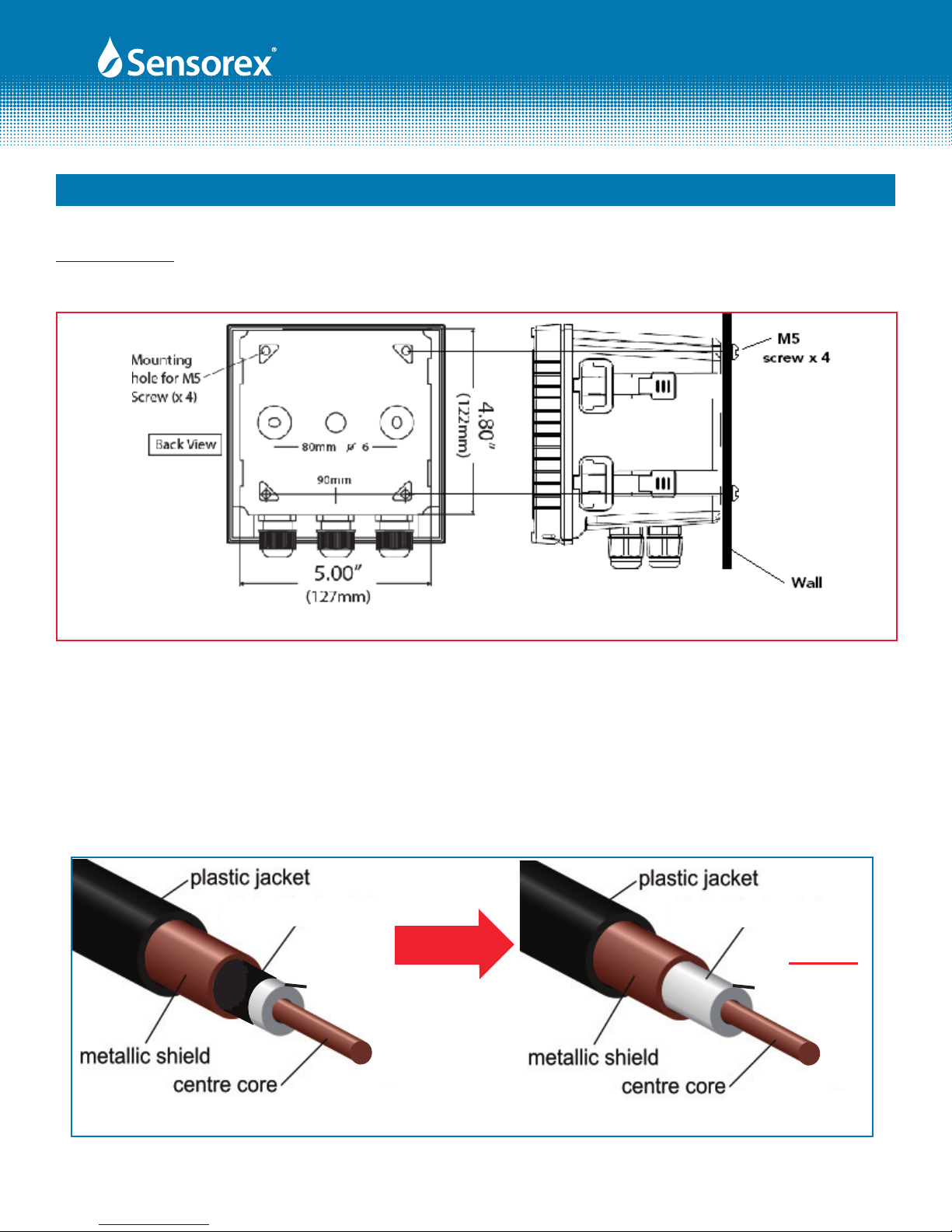
Figure 3-2 Wall Mounting 3
Figure 3-3 Coaxial Cable Preparation 3
Figure 4-1 Rear Panel Illustration 4
Figure 4-2 Terminal Functions 5
Figure 5-1 Front Panel 6
Figure 5-2 Displaty Icons 9
Figure 7-1 Security Settings 11
Figure 7-2 Measurement Parameters 12
Figure 7-3 Temperature Settings 13
Figure 7-4 Standby Mode 14
Figure 7-5 HI Alarm 15
Figure 7-6 LO Alarm 16
Figure 7-7 Wash Alarm 17
Figure 7-8 Analog Output 1, 4-20mA (pH/ORP) 18
Figure 7-9 Analog Output 2, 4-20mA (Temperature) 19
Figure 7-10 Sample Averaging 20
Figure 7-11 LCD Backlight 21
Figure 8-1 Entering Calibration Mode 22
Figure 8-2 2-Point Calibration Mode 23
Figure 8-3 2-Point Calibration Mode Ct1 (Preset buers) 24
Figure 8-4 ORP Calibration 26
Figure 9-1 Troubleshooting Chart 27
Form: INSTRTX3000-Rev A
Table of Contents
PRODUCT INSTRUCTION MANUAL

Part 1 Specications
Page 1 of 29
Measuring Range (pH) -2.00 to 16.00pH, 0.01 pH resolution,
+/- 0.01 accuracy, +/- 1 digit
Measuring Range (ORP/mV) -1999mV to +1999mV, 1mV resolution,
+/- 1mV accuracy, +/- 1 digit
Measuring Temperature Range -30 to 130° C, 0.1° C resolution,
+/- 0.2° C accuracy +/- 1 digit
Calibration Mode Any Tech or NIST buers up to 2 points
Analog Output 1 Isolated DC 0/4-20mA corresponding to pH or ORP,
maximum load 500Ω
Analog Output 2 Isolated DC 0/4-20mA corresponding to temperature,
maximum load 500Ω
Display Large LCD display with environment light sensor auto/manual
illumination function
Weight approx. 1.75lb (0.8kg)
Dimensions 5.7"(144mm) x 5.7"(144mm) x 4.5"(115mm)
Mounting Options Wall mount, panel mount, pipe mount
Panel Cut Out Dimensions 5.4"(138mm) x 5.4"(138mm)
Relays 1(HI) - Contact 110,240 VAC, 0.5A Max - programmable ON/OFF
2(LO) - Contact 110,240 VAC, 0.5A Max - programmable ON/OFF
WASH - Contact 110,240 VAC, 0.5A Max - programmable ON (0-9999 sec),
OFF (0-999.9 hrs)
Ambient/Storage Temperature 0-50° C / -20-70° C
Temperature Compensation NTC 30K Ω or 2-wire Pt1000 RTD auto, manual
Power Requirement 100-240 VAC, 50/60 Hz, software selectable
Voltage Output DC +/-12V(to power external transmitter, if required)
Certication IP 65 (NEMA 4X), CE
Form: INSTRTX3000-Rev A
PRODUCT INSTRUCTION MANUAL

pH / ORP Transmitter TX-3000
(144mm)
5.67”
(144mm)
5.67”
(125mm)
4.92”
(98mm)
3.74”
Cord grip x3
Panel mount
ttings x4
90mm
80mm o6
Front View Side View
(127mm)
5.00”
(122mm)
4.80”
Back View
Mounting
hole for M5
Screw (x 4)
TX3000 Specications - Dimensional Specs
PRODUCT INSTRUCTION MANUAL
Part 1 Specications (cont.)

PRODUCT INSTRUCTION MANUAL
Page 2 of 29
Wrong wiring will lead to breakdown or electrical shock of thetransmitter, please read this operation man-
ual clearly before installation.
• Make sure to remove AC power from the transmitter before wiring input and output connections and
before opening the transmitter housing.
• Install the transmitter in a well ventilated area. Avoid installing in areas receiving direct sunshine.
• The material of signal cable should be special coaxial cable. Strongly recommend using our coaxial
cable. Do not use normal wires instead.
• Avoid electrical surge when using power, especially when using three-phase power, use ground wire
correctly.
• The internal relay contact of the transmitter is for alarm or control function. You must connect to an
external relay which can withstand enough current to ensure safe operation of the transmitter. Please
refer to chapter 4.2“Terminal Functions”
Part 2 Installation Precautions
Part 3 Assembly and Installation
3.1 Transmitter installation: This transmitter can be installed by panel mounting, wall mounting and pipe
mounting.
Panel Mounting: Cut a square hole of 5.4"(138mm) x 5.4"(138mm) on the panel, and then insert the trans-
mitter directly into the panel. Attach the mounting bracket from the rear, so that it attaches to groove.
FIG 3-1
Form: INSTRTX3000-Rev A
Side View with
mounting brackets
Mounting
Bracket
4x
Panel
Panel Cutout
5.4"(138mm)
5.4"(138mm)
minimum distance between
TX3000 panel cutouts = 1.7"(42mm)
PRODUCT INSTRUCTION MANUAL
Page 3 of 29
FIG 3-2
Wall Mounting: Use 4 each M5 screws to attached to mounting holes shown below.
FIG 3-3
clear cover
black noise
reduction
layer
clear cover
black noise
reduction
layer removed
3.2 Coaxial Cable Preparation: Cut coaxial cable plastic jacket o. This will reveal the braided shield wire.
Twist the braid together to reveal black noise reducing layer. Remove the black noise reducing layer even
to the braid (See Fig 3-3). Cut some of clear layer away to expose copper center core.
Part 3 Assembly and Installation (cont.)
Form: INSTRTX3000-Rev A
Wall Mounting

PRODUCT INSTRUCTION MANUAL
Page 4 of 29
Part 4 TX3000 Overview
4.1 Rear Panel:
1 2 3 4 5 6 7 8 9 10 11 12 13 14 15 16 17 18 19 20
100-240
AC
WASH REL 2 REL 1
NC
21
- +
4-20mA
- +
4-20mA
0/4-20mA Isolated MAx load 500Ω
Power: 100~240 VAC +/-10% 50/60Hz
Relay: 240 VAC Max 0.5A (REL1/REL2/WASH)
D-(A)
G
D-(A)
RS-485 Version Only
1 2 3 4 5 6 7 8 9 10 11 12 13 14 15 16 17 18 19 20
- 12V
+ 12V
T/P
SG
REF
NC
GLASS
Important!
Must remove the
jumper between no.
17 & 18 when using
solution ground (SG)
STD (2 Wires)
Meas.
SG (3 Wires) Meas.
ESD Shield cover removed
FIG 4-1
Form: INSTRTX3000-Rev A

PRODUCT INSTRUCTION MANUAL
Page 5 of 29
Part 4 TX3000 Overview (cont.)
GLASS
REF
GND
TP
TP
pH/
ORP
T
HI LO WASH
POWER
AC
INPUT
POWER
TX3000
only
2
4-20mA
4-20mA
1
+/-12V
+
+
+
-
-
-
-
4.2 Terminal Functions:
4.3 Description of terminal function:
1 & 2 - 100~240AC: Power supply terminal
3 & 4 - WASH: External wash relay terminal
5 & 6 - REL2: LO, External relay terminal low control
7 & 8 - REL1: HI, External relay terminal high control
9 - N/C
10 - 4~20mA – terminal /G: Temperature current output terminal -
11 - 4~20mA – terminal /G: Temperature current output terminal +
12 - 4~20mA - terminal: Master measurement current output terminal -
13 - 4~20mA - terminal: Master measurement current output terminal +
14 & 15 +/- 12V output
16 - T/P: temperature probe
17 - SG : Connect the other end of temperature probe, or used as ±12V ground potential. In two-wire distributing
system, there should be a short circuit between this terminal and REF (a short circuit jumper is attached from
the factory)
18 - REF: Coaxial shield connecting pH/ORP electrode signal wire
19 - NC: NC
20 - GLASS: Coaxial inner conductor= pH/ORP electrode signal wire
FIG 4-2
Form: INSTRTX3000-Rev A
Not
Used

PRODUCT INSTRUCTION MANUAL
Page 6 of 29
Part 5 Conguration
5.1 Front Panel:
FIG 5-1
Form: INSTRTX3000-Rev A
PRODUCT INSTRUCTION MANUAL
Page 7 of 29
Part 5 Conguration (cont.)
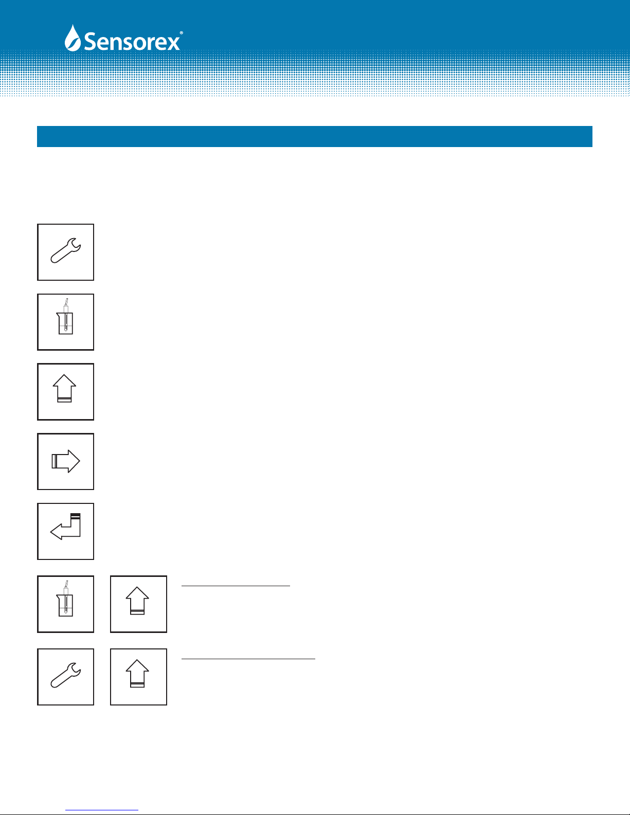
5.2 Function Keys:
Setup
In the parameter set-up mode, pressing this key allows you to exit parameter set-up mode
and go back to Measurement mode.
Cal.
In the Calibration mode, pressing this key allows you exit Calibration mode and back to Mea-
surement mode.
Mode
In the parameter set-up mode and Calibration mode, press this key to increase the value or to
scroll to other function.
In the parameter set-up mode and Calibration mode, press this key to decrease the value or to
scroll to other function.
Enter
Key for conrmation; pressing this key is essential when modifying data value or selecting the
parameter setting items in the window.
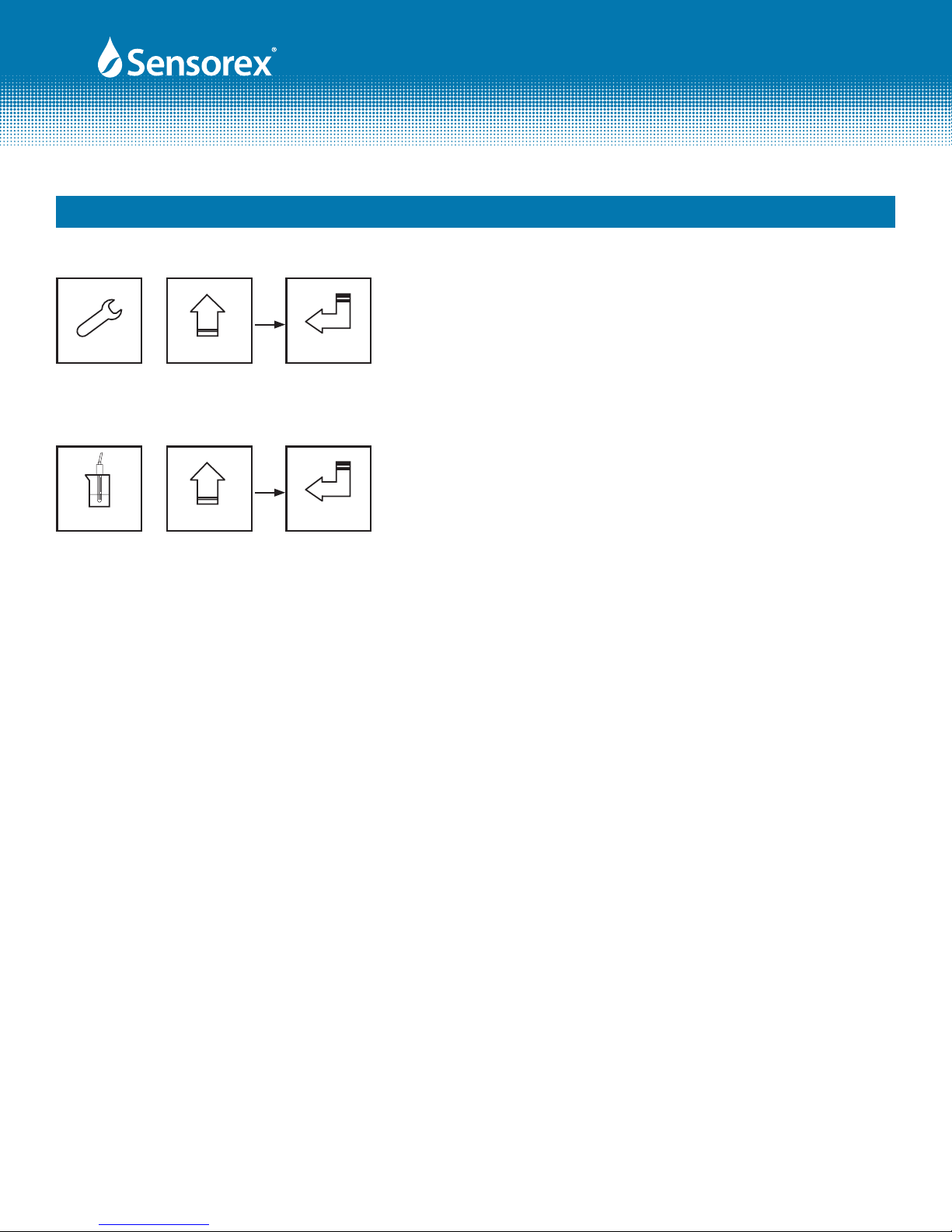
Setup
CALIBRATION MODE
In the Measurement mode, pressing these two keys simultaneously allows you
to enter Calibration mode.
+
Mode
Mode
Cal.
FUNCTION SET-UP MODE
In the Measurement mode, pressing these two keys simultaneously allows you
to enter parameter set-up mode.
+
Form: INSTRTX3000-Rev A
PRODUCT INSTRUCTION MANUAL
Page 8 of 29
Master Reset-Restore factory default parameter’s settings
In the Measurement mode, press the "SETUP" and "MODE" keys
simultaneously for ve seconds, and then press the "ENTER" key
until you see a clock signal appearing on the display. Release all
keys and then factory default settings will be restored.
Setup Mode
+
Part 5 Conguration (cont.)
5 Seconds
Enter
Calibration Reset-Restore factory default calibration settings
In the Measurement mode, press the "CAL" and "MODE" keys
simultaneously for ve seconds, and then press the "ENTER" key
until you see a clock signal appearing on the display. Release all
keys and then factory default calibration settings will be restored.
Mode
+
5 Seconds
Enter
Cal.
5.3 LED indicators:
HI: High set point indicator light; when the high setting point is reached, the REL1 indicator will light.
B.L.: Light sensor; in the automatic display backlit mode, the lamp will light or go out depending on
environmental brightness.
WASH: Washing device indicator light; when the washing device is started up, the indicator will light.
LO: Low set point indicator light; when the high setting point is reached, the REL2 indicator will light.
Form: INSTRTX3000-Rev A
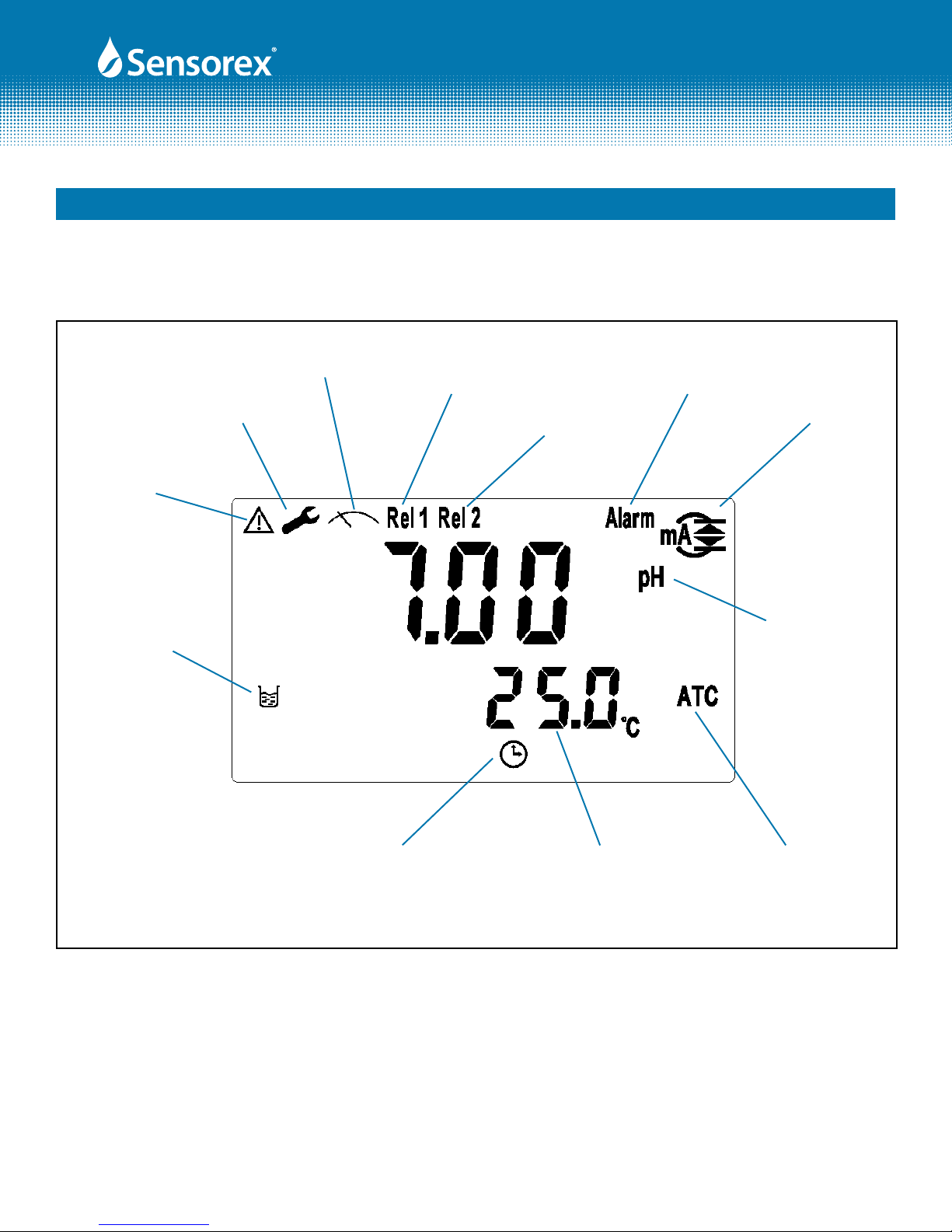
Set Up
Mode
Measurement
Mode Relay 1
Activated
Relay 2
Activated
Clean Device
Activated Output
Current
Over Range
Controller
Function Lock
Calibration
Mode
Temperature Automatic
Temperature
Compensation
Measurement
Units
PRODUCT INSTRUCTION MANUAL
Page 9 of 29
Reset Indicator
(factory/cal)
Part 5 Conguration (cont.)
FIG 5-2
Form: INSTRTX3000-Rev A
5-4 Display Icons:

PRODUCT INSTRUCTION MANUAL
Page 10 of 29
6.1 Measurement mode:
After all electrical connections are nished and tested, connect the transmitter to the power supply and turn
it on. The transmitter will automatically enter measurement mode with the factory default settings or the
last settings from user.
6.2 Set-up mode:
PRESS "SET UP" AND "MODE" SIMULTANEOUSLY
Please refer to the set-up instructions in Chapter 7, and press "SETUP" key to return to measurement mode.
6.3 Calibration mode:
PRESS "CAL" AND "MODE" SIMULTANEOUSLY
Please refer to the calibration instruction in Chapter 8, and press "CAL" key to return to measurement mode.
6.4 Reset:
6.4.1 Master reset:
In the Measurement mode, press the "SETUP" and "MODE" keys simultaneously for ve seconds, and then
press the "ENTER" key until you see a clock signal appearing on the display. Release all keys and then factory
default settings will be restored.
Factory defaults:
Measurement mode: pH
Temperature compensation: MTC 25°C
High point alarm: AUTO, SP1= 10.00 pH,db1= 0.10 pH
Low point alarm: AUTO, SP2 =04.00 pH,db2= 0.10 pH
Wash time: OFF
pH/ORP current output: 4~20 mA, 02.00~12.00pH
TP current output: 4~20 mA, 000.0~100.0˚C
Backlit Display: OFF
Code set-up: OFF
6.4.2 Calibration reset:
In the Measurement mode, press the "CAL" and "MODE" keys simultaneously for ve seconds, and then
press the "ENTER" key until you see a clock signal appearing on the display. Release all keys and then factory
default calibration settings will be restored.
Factory defaults:
OS value: 0 mV SLOPE value: 100.0 %
Calibration mode: Two-Point Calibration: Ct1
Part 6 Operation
Form: INSTRTX3000-Rev A

PRODUCT INSTRUCTION MANUAL
Page 11 of 29
Part 7 Settings
7.1 Set-up mode
In the measurement mode, pressing the "SETUP" and "MODE" keys
simultaneously allows you enter the parameter set-up mode. You can return to
the measurement mode at any time by pressing the key "SETUP" key.
Setup Mode
+
Mode
Enter
7.2 Security
In the set-up mode, you can set up the code by pressing the key "MODE" , and conrm by pressing the
"ENTER" key . The original code is 1111.
When the rst “0” of the digits 0000
ashes, press "MODE" (up arrow)
key or "right arrow" key to input
the code, and press "ENTER" to
conrm. Then, continue inputting
the second digit, the same way and
repeat until all digits are changed.
If you
input the
wrong
code, the
CODE will
ash
4X, and
then the
display
will
return
back for
another
input.
To cancel
security
code,
press
"MODE"
2X
Enter
Enter
GO TO "MEASUREMENT SETUP,
SECTION 7.3
FIG 7-1
Form: INSTRTX3000-Rev A
Enter
Setup

PRODUCT INSTRUCTION MANUAL
Page 12 of 29
Part 7 Settings (cont.)
Enter
Mode
Select pH or ORP. pH is
the default setting.
Enter
GO TO "TEMPERATURE SETUP,
SECTION 7.4
7.3 Measurement Setting
In the measurement mode, you can choose between pH and ORP settings.
FIG 7-2
Form: INSTRTX3000-Rev A
OR PRESS "SET-UP" KEY
TO RETURN TO
MEASUREMENT MODE
PRODUCT INSTRUCTION MANUAL
Page 13 of 29
Part 7 Settings (cont.)
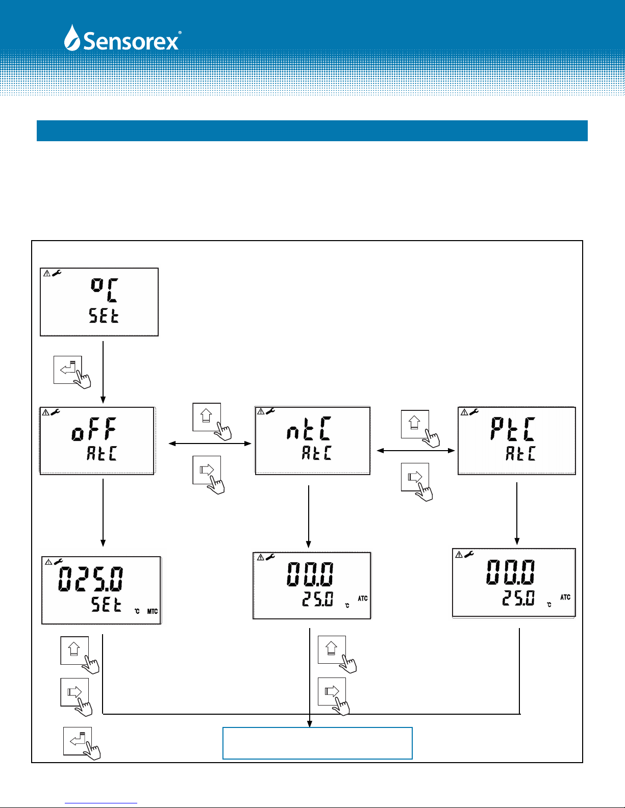
7.4 Temperature Settings
In the Temperature mode you will set the ATC, On or OFF, set the temperature sensor type (PTC or NTC) and
calibrate/adjust the temperature..
Enter
Mode
Mode
GO TO "STANDBY SETUP,
SECTION 7.5
Use a standard thermometer to test the
actual temperature of the solution, and
press "MODE" or "RIGHT ARROW" key to
input the correct temperature value. Press
"ENTER" to conrm.
Mode
If necessary, compare with the
actual temperature value tested by
standard thermometer. Press
"MODE" or "RIGHT ARROW" key to
input the modied value. Press
"ENTER" to conrm.
Mode
Enter
Follow same
steps to left.
FIG 7-3
Form: INSTRTX3000-Rev A
OR PRESS "SET-UP" KEY
TO RETURN TO
MEASUREMENT MODE
Table of contents
Other Sensorex Transmitter manuals

Sensorex
Sensorex TX2000 User manual

Sensorex
Sensorex CT-1000 User manual

Sensorex
Sensorex CX105 User manual

Sensorex
Sensorex TX3100 User manual

Sensorex
Sensorex TX2000 User manual

Sensorex
Sensorex TX100 Specification sheet

Sensorex
Sensorex CX100 User manual

Sensorex
Sensorex TX105 User manual

Sensorex
Sensorex TX2000 User manual


