TERMOSTATO PER FAN-COIL CON ZONA NEUTRA
DEAD BAND FAN-COIL REGULATOR
TFX01M0001AO 023693A2 100614 Mu i-25rev100614
GENERALITÀ
Questo dispositivo è un termostato e ettronico per i contro o
de a temperatura in ambienti risca dati o raffrescati da fan-coi
(venti convettori). Dotato di 2 re è interni, con contatti pu iti,
permette di ottenere una accurata rego azione de a
temperatura ambiente tramite zona neutra. L’a imentazione è a
230V~. I dispositivo è predisposto con un’ingresso per
co egare una sonda di temperatura esterna. Tramite dei
cava ieri meccanici, è possibi e ridurre 'ango o di rotazione
de a manopo a.
INSTALLAZIONE
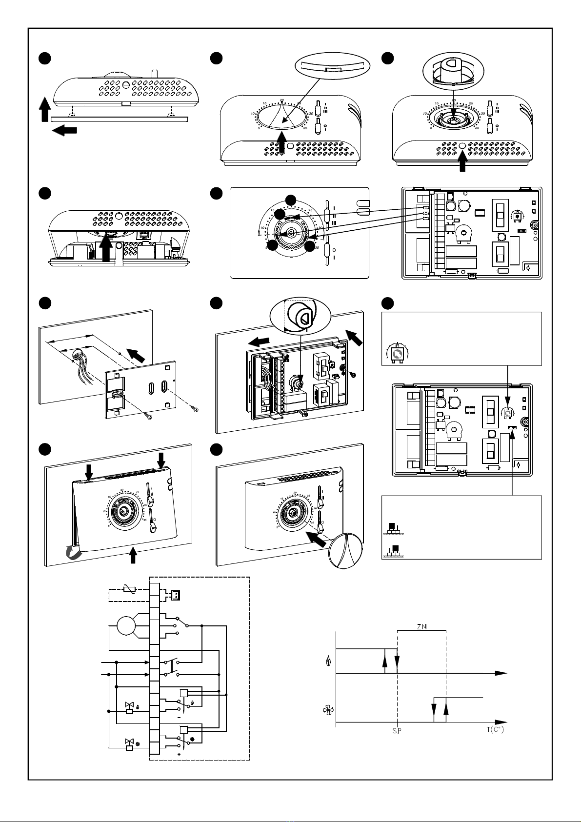
Per insta are i dispositivo eseguire e seguenti operazioni
seguendo e immagini riportate a pagina 2:
Sganciare a piastra attaccata a a base de termostato
spingendo a verso sinistra e facendo cosi' sganciare i
dentini indicati in Fig. 2.
Spostare entrambi g i s ider comp etamente in basso e
posizionare a manopo a su 20°C; quindi so evare a
manopo a facendo eva con un cacciavite ne ’apposito
invito, indicato da a freccia in Fig. 3, facendo attenzione
a non rigare a ca otta.
Spingere, con ’aiuto di un cacciavite, a inguetta p astica
situata ne a feritoia in basso fino a so evare eggermente
a ca otta (Fig. 4).
Ruotare a ca otta esercitando una eggera pressione fino
ad estrar a comp etamente (Fig. 5).
Pre evare i cava ieri meccanici da a base de termostato ed
inserir i opportunamente ne a ca otta in modo da ridurre i
campo di rotazione de a manopo a (vedere 'esempio di
Fig. 6 e eggere i paragrafo 'b occo manopo a'). I terzo
cava iere parcheggiato in a to è di scorta.
Fissare a piastra a a parete tramite e due sedi per viti
con interasse 60 mm oppure 85 mm (uti izzare e viti e/o i
tasse i in dotazione) facendo passare i fi i tramite e
aperture rettango ari.
- Agganciare a base de termostato a a piastra a muro
(facendo passare i fi i tramite e aperture rettango ari)
facendo dapprima coincidere i fori de a base con g i
appositi dentini de a piastra a muro e successivamente
esercitare su a base una pressione verso i ato sinistro
fino a far scattare i dentini p astici de a piastra (Fig. 8).
- Fissare a base de termostato a a piastra a muro
uti izzando a vite in dotazione.
- Eseguire i co egamenti e ettrici seguendo o schema di
co egamento (Fig. 12).
- Se si uti izza una sonda remota, impostare
correttamente i connettore JP1. Vedere i paragrafo
'SELEZIONE SONDA INTERNA / ESTERNA'.
Richiudere i termostato eseguendo e seguenti operazioni:
- Posizionare i due dentini de a parte superiore de a
ca otta neg i appositi intag i e asciare entrambi g i
s ider in basso.
- Ruotare a ca otta facendo in modo che g i s ider
coincidano con i re ativi commutatori e spingere verso
'interno a inguetta p astica posta su a parte inferiore
de a base (indicata da a freccia in Fig. 10) ed esercitare
una pressione che faccia scattare a inguetta p astica di
fissaggio a 'interno de foro su ato inferiore de a
ca otta. Quindi verificare a corretta corsa deg i s ider.
Posizionare a manopo a su 20°C ed inserir a su a ca otta
(Fig. 11).
FUNZIONAMENTO
I comandi de termostato disponibi i per ’utente sono due
se ettori ed una manopo a.
SELETTORE VELOCITA’ MOTORE ( di Fig. 1)
Tramite questo se ettore a quattro posizioni si può sceg iere una
de e tre ve ocita' fisse di attivazione de motore de fan-coi .
SELETTORE ON/OFF ( di Fig. 1)
Questo se ettore a due posizioni permette di attivare o
disattivare i termostato.
Fix the p ate to the wa , using the two screw seats with
centre distances of 60 mm or 85 mm (use the supp ied
wa p ugs and/or screws). Pass the wires through the
rectangu ar openings.
- Connect the thermostat base to the wa p ate (pass the
wires through the rectangu ar openings). A ign the base
ho es with the specia wa p ate teeth, then press the
base to the eft unti the p ate's p astic teeth c ick (Fig. 8).
- Fix the thermostat base to the wa with the supp ied screws.
- Make the e ectrica connections fo owing the connection
diagram (Fig. 13).
- Correct y set the connector JP1 if using a remote sensor.
Se e the " I NTER N A L / E XTER N AL SE N S OR
SELECTION" paragraph.
Perform the fo owing operations to rec ose the thermostat:
- Position the two teeth from the top of the cover into the
specific s ots and eave both s iders at the bottom.
- Turn the cover making sure the s iders coincide with
the re ative switches, push the p astic tab on the ower
part of the base inward y (see the arrow in Fig. 10) and
press it so that the p astic fixing tab inside the specia
ho e, at the bottom of the cover, c icks. Check the
s iders' correct stroke.
Position the knob at 20°C and insert it on the cover (Fig. 11).
OPERATION
The contro s avai ab e on the front cover of the thermostat for
the user are two s iders and one knob.
ON /OFF SELECTOR ( o Fig. 1)
This two-positions se ector a ows to turn on and off the
regu ator.
3-SPEEDS SELECTOR ( o Fig. 1)
Through this three-position s ide se ector the user can choose
the (fixed) speed of the fan-coi motor.
KNOB ( o Fig. 1)
Through the temperature set-point knob the user can set the
temperature desired in the room, according to which the
regu ation wi be performed, in the range +5°C .. +35°C.
KNOB ROTATION LIMITATION
It is possib e to imit the rotation range for the set-poin knob
by fo owing these steps:
1. Extract the knob as indicated in in the "INSTALLATION"
paragraph.
2. Position the mechanica pins as shown in the examp e in
Fig. 6 ( ). The fie d of rotation is, in this way, reduced as in
the arc shown in in Fig. 6.
DEAD BAND
With the interna trimmer, shown in Fig. 9, the user can set
the temperature according to which the dead band regu ation
takes p ace.
The dead band regu ation range is between 1°C and 11°C;
the device is factory set with the dead band programmed at
4°C: Fig. 13 diagram shows the operation moda ity.
INTERNAL / EXTERNAL SENSOR SELECTION
The thermostat eaves the factory a ready set for an interna
sensor work. In those insta ations where a remote sensor is
required, p ease move jumper JP1 ( ocated on the e ectronic
board on the right side of the se ctors) into position A, as
shown in Fig. 9, then wire a 10KΩ @ 25°C NTC sensor with
a proper 'Beta' va ue at connector SA or, as an a ternative, at
termina s 13 and 14. In case of doubts about the sensor to be
connected, p ease ask the producer.
TECHNICAL FEATURES
Power supp y: 230V~ -15% +10% 50/60Hz
Power absorption: 3VA
Contact rating: 2 x 5(1) A @ 250V~ SPDT
Sensor type: NTC 10KΩ @ 25°C ±1% interna
(remote optiona )
Regu ation range: 5°C .. 35°C
Dead Band regu ation range: 1°C .. 11°C (Defau t 4°C)
Accuracy: ± 1°C
Reso ution: 1°C
Hysteresis: 0.5°C
Operating temperature: 0°C .. 40°C
Storage temperature: -10°C .. +50°C
Humidity imits: 20% .. 80% RH (non condensing)
Protection grade: IP 30
Case: Materia : ABS se f-extinguishing V0
Co or: Signa white (RAL 9003)
Size: 132 x 87 x 37 mm (W x H x D)
Weight: ~243 g
a
WARNING
- To adjust properly room temperature, install the thermostat
ar rom heat sources, airstreams or particularly cold walls
(thermal bridges). When the remote sensor is used in
conjunction with the thermostat, then this note must be
applied to the remote sensor itsel .
- For remote versions all wirings must be made using wires
with 1,5 mm² minimum cross section and not longer than
25 m. Do not use same duct or signal wires and mains.
- The appliance must be wired to the electric mains
through a switch capable o disconnecting all poles in
compliance with the current sa ety standards and with a
contact separation o at least 3 mm in all poles.
- Installation and electrical wirings o this appliance must
be made by quali ied technicians and in compliance with
the current standards.
- Be ore wiring the appliance be sure to turn the mains
power o .
WARRANTY
In the view of a constant deve opment of their products, the
manufacturer reserves the right for changing technica data
and features without prior notice. The consumer is
guaranteed against any ack of conformity according to the
European Directive 1999/44/EC as we as to the
manufacturer’s document about the warranty po icy. The fu
text of warranty is avai ab e on request from the se er.
MANOPOLA ( di Fig. 1)
Tramite a manopo a di rego azione è possibi e impostare a
temperatura attorno a cui verrà effettuato i contro o de a temperatura
desiderata che può essere compresa tra +5°C .. +35°C.
BLOCCO MANOPOLA
E' possibi e ridurre i campo entro cui ruota a manopo a
eseguendo i seguenti passi:
1. Estrarre a manopo a come indicato in ne paragrafo
"INSTALLAZIONE".
2. Posizionare i cavaieri meccanici come indicato ne 'esempio di
Fig. 6 ( ). In questo modo i campo di rotazione e' ridotto
come ne 'arco indicato in di Fig. 6.
ZONA NEUTRA
Tramite i trimmer interno, visibi e in Fig. 9, è possibi e
impostare a temperatura attorno a qua e i termostato rego a
a zona neutra. I campo di rego azione è compreso tra
1°C .. 11°C; i dispositivo esce da a fabbrica con a zona
neutra impostata a 4°C.
I diagramma in Fig. 13, mostra a moda ità di attivazione.
SELEZIONE SONDA INTERNA / ESTERNA
I termostato esce da a fabbrica predisposto per i
funzionamento con sonda interna.
Ne caso in cui 'insta azione preveda un montaggio con
sonda a distanza, è necessario spostare i pontice o JP1 in
A, come indicato in Fig. 9, (posizionato su a scheda interna a
destra dei se ettori), e co egare una sonda di tipo NTC da
10KΩ a 25°C con adeguato va ore per i parametro beta a
connettore SA oppure in a ternativa ai morsetti 13 e 14.
In caso di dubbio su tipo di sonda da co egare si prega di
consu tare i costruttore.
CARATTERISTICHE TECNICHE
A imentazione: 230V~ -15% +10% 50/60Hz
Potenza assorbita: 3VA
Portata contatti: 2 x 5(1)A @ 250V~ SPDT
Tipo di sensore: NTC 10KΩ @ 25°C ±1% interno
(esterno opziona e)
Campo di rego azione: 5°C .. 35°C
Campo di rego azione
Zona Neutra: 1°C .. 11°C (Defau t 4°C)
Precisione: ± 1°C
Riso uzione: 1°C
Isteresi: 0.5°C
Temp. di funzionamento: 0°C .. 40°C
Temp. di stoccaggio: -10°C .. +50°C
Limiti di umidità: 20% .. 80% RH (non condensante)
Grado di protezione: IP 30
Contenitore: Materia e: ABS autoestinguente V0
Co ore: Bianco segna e (RAL 9003)
Dimensioni: 132 x 87 x 37 mm (L x A x P)
Peso: ~243 g
a
ATTENZIONE
- Per una corretta regolazione della temperatura ambiente
si consiglia di installare il termostato lontano da onti di
calore, correnti d'aria o da pareti particolarmente redde
(ponti termici). Se si usa una sonda a distanza la nota va
applicata alla sonda e non al termostato.
- Per i collegamenti della sonda usare cavi di sezione
minima 1,5 mm² e di lunghezza massima di 25 m. Non
passare i cavi della sonda nelle canaline della rete.
- Collegare l'apparecchio alla rete di alimentazione
tramite un interruttore onnipolare con orme alle norme
vigenti e con distanza di apertura dei contatti di almeno
3 mm in ciascun polo.
- L'installazione ed il collegamento elettrico del
dispositivo devono essere eseguiti da personale
quali icato ed in con ormità alle leggi vigenti.
- Prima di e ettuare qualsiasi collegamento accertarsi
che la rete elettrica sia scollegata.
GARANZIA
Ne 'ottica di un continuo svi uppo dei propri prodotti, i
costruttore si riserva i diritto di apportare modifiche a dati
tecnici e prestazioni senza preavviso. I consumatore è
garantito contro i difetti di conformità de prodotto secondo a
Direttiva Europea 1999/44/c nonché i documento su a
po itica di garanzia de costruttore. Su richiesta è disponibi e
presso i venditore i testo comp eto de a garanzia.
ITALIANO
ENGLISH
OVERVIEW
This device is a thermostat intended for temperature
regu ation in environments heated or coo ed with fan-coi
units. Featuring 2 interna re ays (vo tage free), this device
ensures accurate temperature regu ation through the dead
band operation. Power supp y is 230V~. The device features
an out et to connect an externa temperature probe.
By means of the mechanica pins the ang e of rotation of the
knob can be reduced.
INSTALLATION
Carry out the operations be ow to insta the device, whi e
fo owing the images on page 2:
Re ease the p ate attached to the thermostat base by
pushing it to the eft. This re eases the teeth shown in Fig. 2.
Move both s iders a the way down and position the knob
at 20°C; ift the knob using a screwdriver as shown by the
arrow in Fig. 3, being carefu not to scratch the cover.
Push the p astic tab in the ower s ot using a screwdriver,
s ight y ifting the cover (Fig. 4).
Turn the cover, whi e pressing it s ight y, unti it is fu y
extracted (Fig. 5).
Remove the mechanica pins from the thermostat base
and insert them in the cover to reduce the knob's fie d of
rotation (see examp e in Fig. 6 and read the "knob ock"
paragraph). The third pin at the top is a spare.
LEGENDA - LEGEND
Se ettore ve ocità motore - Motor speed selector
Se ettore a 2 posizioni: ON/OFF
Two-position selector: ON/OFF
Manopo a rego azione temperatura ambiente
Adjustment Knob room temperature
Led verde acceso: attivazione condizionamento
Green led on: Cooling acti e
Led rosso acceso: attivazione risca damento
Red led on: Heating acti e
A
B
C
D
E
9
10
8
7
6
5
4
3
2
1
9
10
8
7
6
5
4
3
2
1
A
B
C
2
F G
A
2
F G
B
C
Fig. 1
C
A
B
D
E
1
i-25
i-25