Form #5154 3.1.03 ©Research Products Corporation 2003
PRODUCT SPECIFICATIONS
Rated Voltage 20 to 30 Volts AC or DC, 24 Volts Nominal
Rated AC Current .050 Amps to 0.75 Amps continuous per output with surges to 3 Amps maximum
Rated DC Current 0.0 Amps to 0.75 Amps continuous per output with surges to 3 Amps maximum
Control Range Heating: 38 to 88˚F in 1˚ steps {5 to 30˚C in 1˚ steps}
Cooling: 60 to 108˚F in 1˚ steps {16 to 40˚C in 1˚ steps}
Thermostat Measurement Range 28 to 124˚F {0 to 48˚C}
ODT Measurement Range –50 to 124˚F {–48 to 48˚C}
Control Accuracy ±1˚F at 68˚ {0.5˚C at 20˚C}
Minimum Deadband {between heating and cooling set points} 2˚F {1˚C}
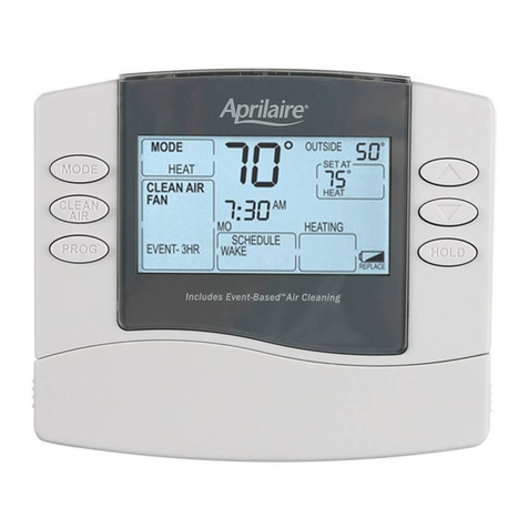
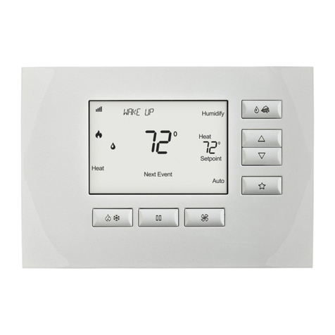
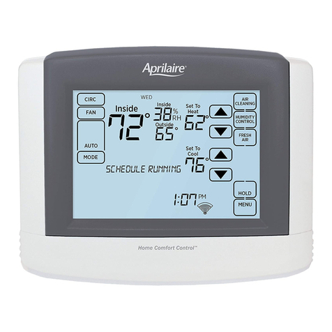
Dimensions 8555 41/2"H x 5"W x 7/8"D {114mm x 127mm x 22mm}
8537 41/2"H x 4"W x 7/8"D {114mm x 102mm x 22mm}
Available Equipment Terminals 8555 24 Vac, 24 Vac{c}, W2, Y2, W1, Y1, G, O/B
8537 24 Vac, 24 Vac{c}, Y1, Y2, W1, G, O/B
Minimum Wires Required 8555 8
8537 7
NOTE: These thermostats contain electronic circuitry in place of the conventional mechanical anticipator. Specifications are subject to change without notice.
B
24V
G
Y1
W1
Y2
W2
O
R
NC
NO
RS+v
RS1
CLK2
CLK1
RS2
COM
REMOTE
SENSOR{S}
CLOCK
TERMINALS
EQUIPMENT TERMINALS
EQUIPMENT
24V(c)
LED2
LED1
FREE
RELAY
Models SHP-2 or DSL-600
{com}
{hot}
24 V
120 V
1st Stage
Aux. Heat
Fan
Relay
2nd Stage
Emer. Heat
2nd Stage
Compressor
1st Stage
Compressor
Reversing
Valve – Heat
Reversing
Valve – Cool
W2
Y2
W1
Y1
G
R
C
B
O
FACTORY WIRING
24V FIELD WIRING
NOTE 2
NOTE 3
NOTE 4
NOTE 1
PerfectTemp®
Thermostat
NOTE 1: Do not remove jumper unless using a
transformer different from system transformer
to power the thermostat.
NOTE 2: Thermostat will accept 24V DC. Connect pos. {+}
to 24V terminal and neg. {–} to 24V{c} terminal.
NOTE 3: Connect service light output from heat pump to LED2.
NOTE 4: Free relay for field use. Relay energizes during the night
event {partial moon shown on display}. {8555 only}
OUTPUT TERMINALS
W2 2nd Stage Emergency Heat {8555 only}.
W1 3rd Stage Heat {aux. heat} or 1st Stage Emerg.
Heat. Center LED lights when this terminal is
energized.
Y2 2nd Stage Cooling Compressor
Y1 1st Stage Cooling Compressor
GFan
R24V hot – used with terminals above to complete
switched circuit.
24V 24V {AC or DC} hot from transformer {positive if
DC voltage source is used}.
24V{c} 24V {AC or DC} common from transformer
{negative if DC voltage source is used}.
OReversing Valve, Cooling – energizes in Cool mode.
BReversing Valve, Heating – energizes in Heat mode.
NC, Single Pole Double Throw relay with default as
COM, indicated. During the Night event {moon shows on
NO display}, the relay is energized {8555 only}.
LED1, Completing a circuit from the hot side of
LED2 the thermostat transformer {through a switch}
to either of these terminals illuminates the
appropriate LED located on top of the thermostat.
RS1, These terminals are used to connect Remote
RS2, Sensors {i.e. 8040, 8041}.
RS+v
CLK1, A completed circuit between these two
CLK2 terminals automatically adjusts the set point
to the night setting in the current mode of
operation {8537 only}.
WIRING DIAGRAM
Models 8555, 8537
P. O. BOX 1467 • MADISON, WI 53701-1467 • Call toll-free 1-800/334-6011 • FAX 608/ 257-4357 • Products For Better Indoor Air Quality™
Aprilaire®
Thermostat
®
