Advanced instructions
EN
VTS reserves the right to implement changes without prior notice
4
II. ADVANCED INSTRUCTIONS
CAUTION!
!
All works related to the inner elements of the control gear should be carried out with the power of external control
circuits turned off by means of the X3 strip. Even if the mains switch Q1 of the control gear is turned off, some external
circuits control voltage may be present at the X3 strip.
3. DETAILED DESCRIPTION OF THE CONTROL GEAR
3.1. EAHU Output Control
The VTS-E-0006 electronic module of VS...CG-0-1 control gears enables gradual adjustment of exhaust AHUs’ air capacity by means of
selecting one of three, previously programmed , reference frequencies of 2U1 to 2U4 inverters (two inverters can appear in AHUs over
VS150, four inverters can appear in AHUs over VS 300).
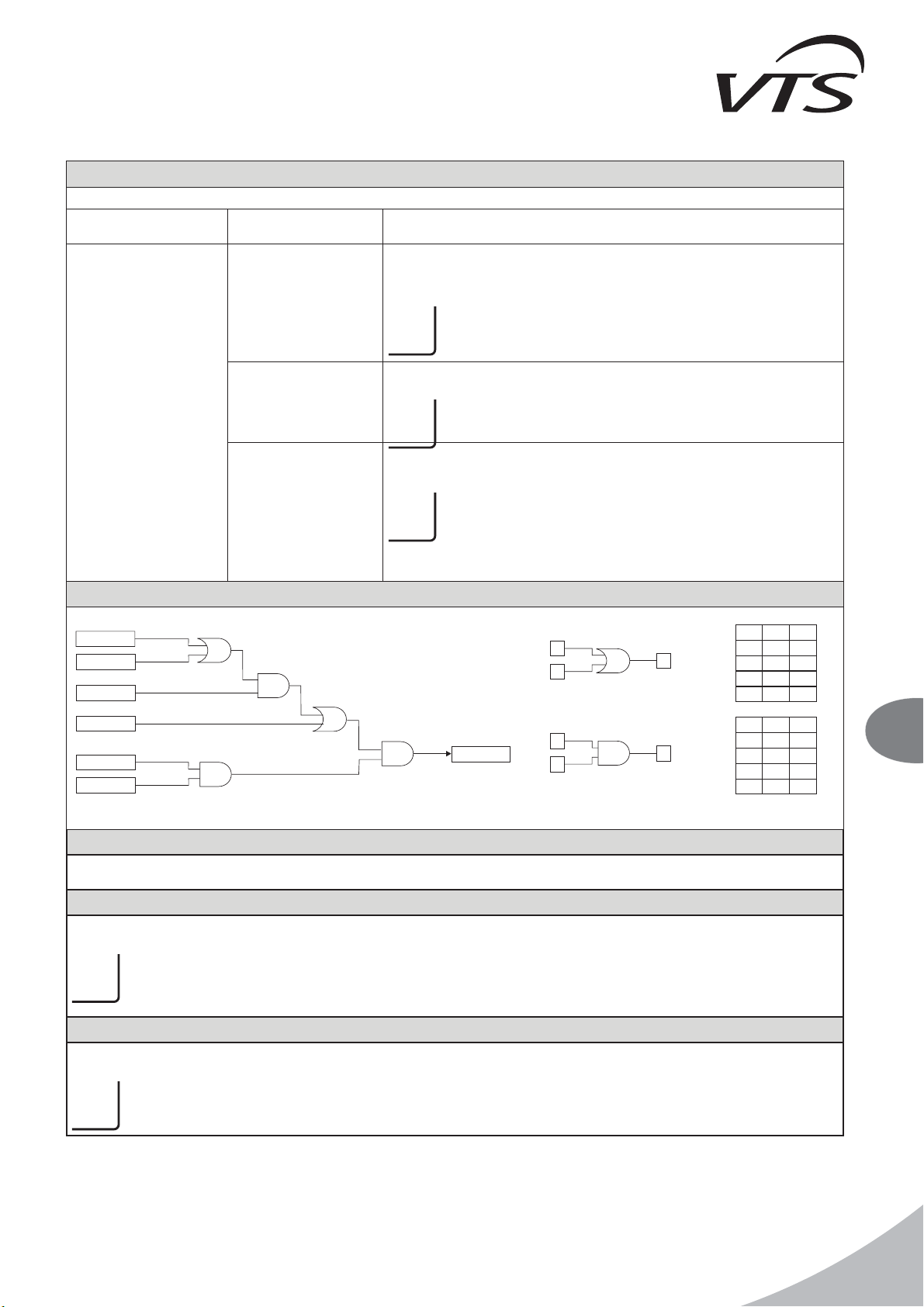
Converter control output X3:1 X3:5 consists of four voltage-free operating contacts with a joint COM terminal. Number of output circuit
contacts shorted with COM terminal decides about functioning of the converter as well as speed selection.
!
Stimulation of converter inputs is carried out by its internal charger.
Status of control output Converter operation
X3:2 START -
X3:3 FC I -
X3:4 FC II -
X3:5 FC III -
Converter stopped
X3:2 START x
X3:3 FC I x
X3:4 FC II -
X3:5 FC III -
Converter started, speed I
X3:2 START x
X3:3 FC I x
X3:4 FC II x
X3:5 FC III -
Converter started, speed II
X3:2 START x
X3:3 FC I x
X3:4 FC II x
X3:5 FC III x
Converter started, speed III
Control of converter's speed depends on the signals coming from three requesting channels, which may be disconnected from the
module.
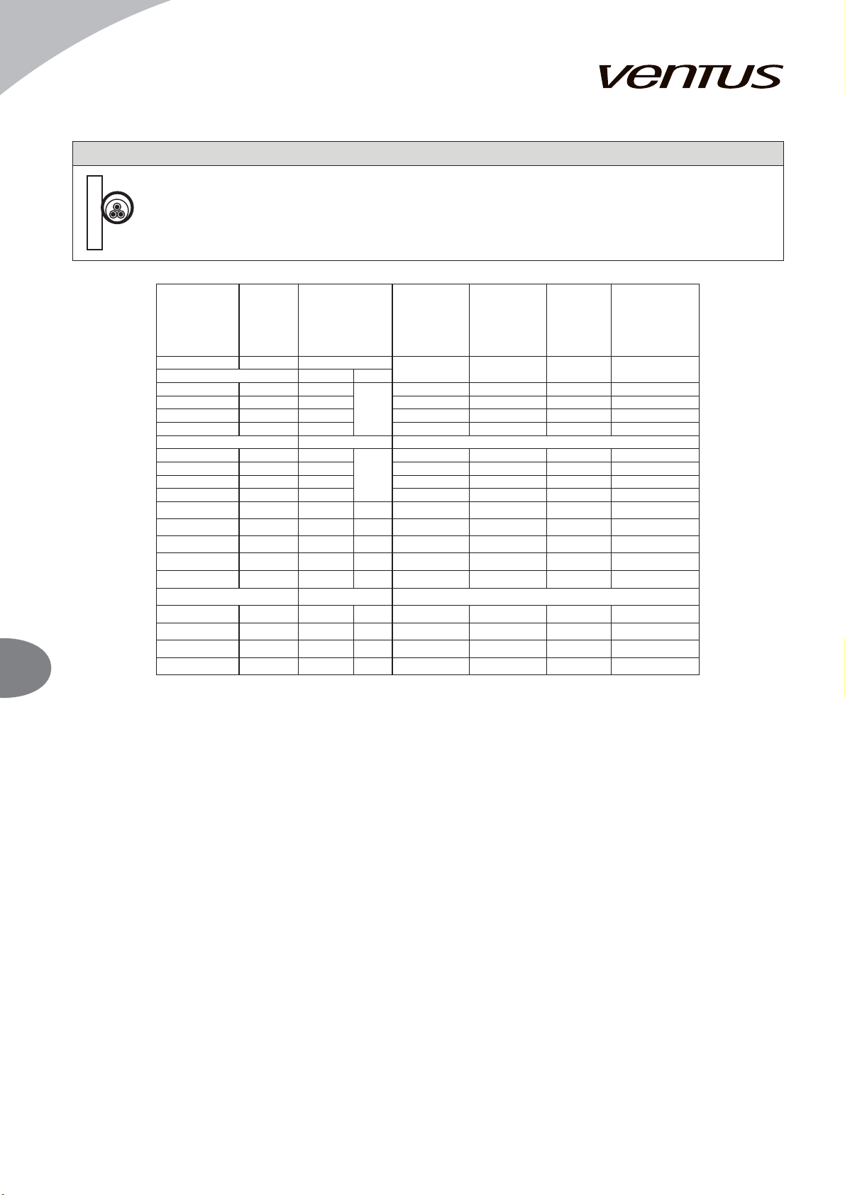
Source of control Control channel;
Connection place Function
Local control LOC - channel 1
connection J12
Exhaust fan speed can be controlled from the front of the control gear.
Remote control
RC – channel 2
X3:13 X3:16
Exhaust fan speed can be controlled through remote control signal coming from
e.g.: switch, supply unit controller, master control system.
CO – channel 3
X3:6 X3:10
Exhaust fan speed can be controlled through CO detection module, depending
on CO concentration in a room.
Processing of alarm signal from the CO detection module is an additional
function of this channel. In case of the CO detector alarm, the EAHU will operate
at maximum, speed.
!
Signal of set frequency for the 2U1 to 2U4 converters equals the highest input set signal LOC, RC and CO.
EC MOTORS
EC motors require the use of a module to convert the switched signal - binary to 0-10V analog signal. Speed setting for gears I and II is
done using the potentiometers on the module. Gear III is always set to the maximum engine speed - 10V control signal. Direct voltage +
10VDC is applied to terminal X3.1. The voltage is switched and fed to the inputs module. A 0-10V signal appears at the output according
to the running gear. The module detects the situation setting by means of potentiometers smaller signals for gear II in relation to I. In
such a situation the red LED flashes (state of error) and the output will show a 0V signal (engine stop).
When using the EC-PCB (1-2-1209-0062) expansion board to control the unit, the DIP-SWITCH located on it should be properly set to
ensure correct communication with EC motors:
-supply unit (motors with Modbus addresses in the range of 40-49): DIP_5 = 1, DIP_6 = 0
-extraction unit (motors with Modbus addresses in the range 50-59): DIP_5 = 1, DIP_6 = 1
In the default configuration, the other switches should remain in the 0 position.
The control rules for the switchgear are identical to those for an AC motor with a frequency converter.