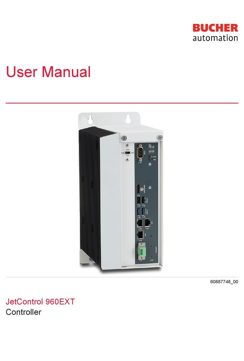
Bucher JetControl 960EXT-E03-2 User manual

User Manual
JetControl 960EXT-E03-2
Controller
60887747_00

Bucher Automation AG has created this document with the requisite care and based on the current state of tech-
nology. Changes and further technical developments to our products are not automatically made available in a
revised document. Bucher Automation AG shall accept no liability or responsibility for errors of content or form,
missing updates or any damage or disadvantages arising therefrom.
Bucher AutomationAG
Thomas-Alva-Edison-Ring 10
71672 Marbach/Neckar, Germany
T +49 7141 2550-0
Technical hotline
T +49 7141 2550-444
Sales
T +49 7141 2550-663
www.bucherautomation.com
Translation of the german original User Manual
Revision 1.00
Date of issue 10/10/2023

Bucher Automation AG Table of contents
User Manual – JetControl 960EXT-E03-2 iii
Table of contents
1 Introduction........................................................................................................................................... 7
1.1 Information on this document ................................................................................................................. 7
1.2 Typographical conventions..................................................................................................................... 7
2 Safety..................................................................................................................................................... 8
2.1 General Information................................................................................................................................ 8
2.2 Purpose .................................................................................................................................................. 8
2.2.1 Intended use........................................................................................................................................... 8
2.2.2 Usage other than intended ..................................................................................................................... 8
2.3 Warnings used in this document ............................................................................................................ 9
3 Product description.............................................................................................................................. 10
3.1 JC-96xEXT-xxx product family overview ................................................................................................ 10
3.2 System overview .................................................................................................................................... 11
3.3 Design .................................................................................................................................................... 12
3.4 Product features ..................................................................................................................................... 13
3.5 Axis engineering guidelines.................................................................................................................... 13
3.6 Required axis licenses............................................................................................................................ 14
3.7 Status indication ..................................................................................................................................... 14
3.7.1 LED states during the boot process ....................................................................................................... 14
3.7.2 PWR and RSQ LED ............................................................................................................................... 15
3.8 Nameplate .............................................................................................................................................. 16
3.9 Scope of delivery .................................................................................................................................... 16
4 Technical data....................................................................................................................................... 17
4.1 Dimensions............................................................................................................................................. 17
4.2 Mechanical specifications....................................................................................................................... 18
4.3 Electrical properties ................................................................................................................................ 18
4.4 Real-time clock ....................................................................................................................................... 21
4.5 Environmental conditions ....................................................................................................................... 21
4.6 EMI values.............................................................................................................................................. 21
4.6.1 Housing .................................................................................................................................................. 21
4.6.2 Shielded data and I/O lines .................................................................................................................... 22
4.6.3 DC power supply inputs and outputs...................................................................................................... 22
5 Mechanical installation ........................................................................................................................ 24
5.1 Installing the controller............................................................................................................................ 24
5.2 Removing the controller.......................................................................................................................... 24
5.3 Installing JI-PCIE-Exx riser cards ........................................................................................................... 25
5.4 Replacing the fastening lugs .................................................................................................................. 28

Bucher Automation AG Table of contents
User Manual – JetControl 960EXT-E03-2 iv
6 Electrical connection ........................................................................................................................... 31
6.1 Improving noise immunity....................................................................................................................... 31
6.2 Jack X101 – power supply...................................................................................................................... 32
6.3 Jack X102 – Ethernet ............................................................................................................................. 32
6.4 Jacks X103, X104 – Ethernet ................................................................................................................. 32
6.5 Jack X105-X108 – USB.......................................................................................................................... 33
6.6 PCI express slots X81, X82, X91, X92 ................................................................................................... 33
6.6.1 JX2 system bus interface ....................................................................................................................... 34
6.6.2 JX6-IO submodules for local I/Os........................................................................................................... 35
7 Control elements .................................................................................................................................. 38
7.1 Mode selector S11.................................................................................................................................. 38
7.2 PWR button ............................................................................................................................................ 39
7.3 RSQ button............................................................................................................................................. 39
8 Identification ......................................................................................................................................... 40
8.1 Electronic Data Sheet (EDS) .................................................................................................................. 40
8.1.1 EDS file "eds.ini"..................................................................................................................................... 40
8.1.2 EDS registers ......................................................................................................................................... 42
8.2 Version registers..................................................................................................................................... 43
8.2.1 Hardware revisions................................................................................................................................. 43
8.2.2 Operating system version....................................................................................................................... 43
9 Configuration ........................................................................................................................................ 44
9.1 Default values......................................................................................................................................... 44
9.2 Configuration file "config.ini"................................................................................................................... 46
9.2.1 Changing the configuration using the configuration file.......................................................................... 47
9.2.2 Section [IP] ............................................................................................................................................. 47
9.2.3 Section [HOSTNAME] ............................................................................................................................ 49
9.2.4 Section [PORTS] .................................................................................................................................... 50
9.2.5 Section [FILES]....................................................................................................................................... 50
9.3 Non-volatile configuration settings via registers ..................................................................................... 51
9.4 Setting the IP address automatically via USB flash drive....................................................................... 52
9.5 Setting the IP address during runtime .................................................................................................... 53
9.6 Changing the IP address using the JetIPScan command line tool......................................................... 54
10 Operating system ................................................................................................................................. 57
10.1 Operating system update of the controller.............................................................................................. 57
10.1.1 Operating system update using the programming tool........................................................................... 57
10.1.2 Updating the operating system by means of FTP .................................................................................. 57
10.1.3 OS update from a USB flash drive ......................................................................................................... 58
10.1.4 Updating the OS from within the application program ............................................................................ 58

Bucher Automation AG Table of contents
User Manual – JetControl 960EXT-E03-2 v
11 File System............................................................................................................................................ 60
11.1 Properties ............................................................................................................................................... 60
11.1.1 Flash disk - Properties............................................................................................................................ 61
11.1.2 USB flash drive - Properties ................................................................................................................... 61
12 Programming ........................................................................................................................................ 62
12.1 Abbreviations, module register properties and formats .......................................................................... 62
12.2 Storage options - Overview .................................................................................................................... 63
12.2.1 Operating system memory ..................................................................................................................... 63
12.2.2 File system memory ............................................................................................................................... 63
12.2.3 Application Program Memory ................................................................................................................. 63
12.2.4 Memory for volatile application program variables ................................................................................. 64
12.2.5 Memory for non-volatile application program registers........................................................................... 65
12.2.6 Special registers ..................................................................................................................................... 66
12.2.7 Registers on I/O modules ....................................................................................................................... 67
12.2.8 Flag......................................................................................................................................................... 67
12.2.9 Digital inputs and outputs ....................................................................................................................... 68
12.3 Saving and loading an application program ........................................................................................... 68
12.4 Addressing of registers and I/Os ............................................................................................................ 69
12.5 Local JX6-IO module register slot numbering ........................................................................................ 70
12.5.1 Register numbers of the submodule JX6-SB(-I)..................................................................................... 71
12.5.2 Register numbers of JX2 slave modules connected to the JX2 system bus .......................................... 72
12.5.3 JX2 and JX3 module register numbers and I/O numbers on the JX2 system bus ................................. 74
12.5.4 Register numbers and I/O numbers of the JX6-IO16CB digital submodule ........................................... 76
12.5.5 Register numbers of the JX6-SV1-ES counter module .......................................................................... 80
12.6 Addressing JX3-IO expansion modules on the Ethernet system bus..................................................... 85
12.6.1 Numbering registers and I/Os................................................................................................................. 85
12.6.2 Expansion modules connected to an Ethernet bus node ....................................................................... 86
12.7 Addressing JM-2xx-ETH servo amplifiers on the Ethernet system bus.................................................. 89
12.8 Option model .......................................................................................................................................... 89
12.8.1 Available firmware functions................................................................................................................... 89
12.8.2 License File ............................................................................................................................................ 91
12.9 System commands ................................................................................................................................. 92
12.10 Real-time clock ....................................................................................................................................... 92
12.11 Startup delay time................................................................................................................................... 93
12.12 System runtime registers........................................................................................................................ 93
12.13 Monitoring interface activities ................................................................................................................. 93
12.14 Ethernet system bus............................................................................................................................... 93
12.15 JCF-SV1 "simple servo function"............................................................................................................ 94

Bucher Automation AG Table of contents
User Manual – JetControl 960EXT-E03-2 vi
12.16 E-mail feature ......................................................................................................................................... 95
12.17 Modbus/TCP........................................................................................................................................... 96
12.17.1 Modbus/TCP server................................................................................................................................ 97
12.17.2 Modbus/TCP client with STX functions .................................................................................................. 99
12.18 User-programmable IP interface ............................................................................................................100
12.19 Motion control .........................................................................................................................................100
12.20 MQTT client ............................................................................................................................................102
12.21 OPC UA server.......................................................................................................................................102
12.22 OPC UA client ........................................................................................................................................103
13 FTP server .............................................................................................................................................104
14 HTTP server ..........................................................................................................................................105
15 Device Dashboard ................................................................................................................................106
16 FTP client ..............................................................................................................................................108
17 Automatic copying of controller data (AutoCopy) ............................................................................109
18 Registers - Overview ............................................................................................................................110
19 Maintenance..........................................................................................................................................131
19.1 Repairs ...................................................................................................................................................131
19.2 Storage and shipment ............................................................................................................................131
19.3 Return and disposal................................................................................................................................132
20 Service...................................................................................................................................................133
20.1 Customer service....................................................................................................................................133
21 Spare parts and accessories...............................................................................................................134
21.1 Accessories ............................................................................................................................................134
21.1.1 Ethernet Cable........................................................................................................................................134
21.1.2 PCI express expansion cards.................................................................................................................134
21.1.3 USB flash drives .....................................................................................................................................135
21.1.4 Fastening lugs for upgrading from JC-94x to JC-96x .............................................................................135

Bucher Automation AG Introduction | 1
User Manual – JetControl 960EXT-E03-2 7
1 Introduction
1.1 Information on this document
This document forms an integral part of the product and must be read and understood
prior to using it. It contains important and safety-related information for the proper use
of the product as intended.
Target groups This document is intended for specialists with appropriate qualifications.
Only competent and trained personnel is allowed to put this device into operation.
During the whole product life cycle, safe handling and operation of the device must be
ensured. In the case of missing or inadequate technical knowledge or knowledge of this
document any liability is excluded.
Availability of
information
Make sure this document is kept at the ready in the vicinity of the product throughout its
service life.
For information on new revisions of this document, visit the download area on our web-
site. This document is not subject to any updating service.
Start | Bucher Automation - We automate your success.
For further information refer to the following information products:
– JetSym software Online Help
Detailed description of software functions with application examples
– Application-oriented manuals
Cross-product documentation
– Version updates
Information about new versions of software products or of the operating system of
your device
1.2 Typographical conventions
This manual uses different typographical effects to support you in finding and classify-
ing information. Below, there is an example of a step-by-step instruction:
üThis symbol indicates requirements which have to be met before executing the fol-
lowing action.
►This sign or a numbering at the beginning of a paragraph marks an action instruc-
tion that must be executed by the user. Execute the instructions one after the
other.
ðThe target after a list of instructions indicates reactions to, or results of these ac-
tions.
INFO Further information and practical tips
In the info box you will find helpful information and practical tips
about your product.

Bucher Automation AG Safety | 2
User Manual – JetControl 960EXT-E03-2 8
2 Safety
2.1 General Information
When placed on the market, this product corresponds to the current state of science
and technology.
In addition to the operating instructions, the laws, regulations and guidelines of the
country of operation or the EU apply to the operation of the product. The operator is re-
sponsible for compliance with the relevant accident prevention regulations and gener-
ally accepted safety rules.
2.2 Purpose
2.2.1 Intended use
This device has been designed to control machinery, such as conveyors, production
machines, and handling machines.
Operate the device only in accordance with the intended conditions of use, and within
the limits set forth in the technical specifications.
Intended use of the product includes its operation in accordance with this manual.
SELV The operating voltage of this device is classified as Safety Extra Low Voltage and is
therefore not subject to the European Low Voltage Directive. The device may only be
operated from a SELV source.
2.2.2 Usage other than intended
This device must not be used in technical systems which to a high degree have to be
fail-safe.
Machinery Directive This device is no safety-related part as per Machinery Directive 2006/42/EC, and must,
therefore, not be used for safety-relevant applications. This device is NOT intended for
the purpose of personal safety, and must, therefore, not be used to protect persons.

Bucher Automation AG Safety | 2
User Manual – JetControl 960EXT-E03-2 9
2.3 Warnings used in this document
DANGER
High risk
Indicates an imminently hazardous situation which, if not avoided,
will result in death or serious injury.
WARNING
Medium risk
Indicates a potentially hazardous situation which, if not avoided,
could result in death or serious injury.
CAUTION
Low risk
Indicates a hazardous situation which, if not avoided, could result
in minor or moderate injury.
NOTICE
Material damage
Indicates a situation which, if not avoided, could result in malfunc-
tions or material damage.

Bucher Automation AG Product description | 3
User Manual – JetControl 960EXT-E03-2 10
3 Product description
The JC-960EXT-E03-2 control system has been designed to deliver upper-range per-
formance. Offering extensive scalability options, it is suited to all areas of industrial au-
tomation.
Besides traditional controller functions, the JC-960EXT-E03-2 offers an optional motion
control feature allowing for the programming of servo drives in a point-to-point (PtP),
axis group and complex path control setup.
Thanks to the option model, users are flexible to extend the range of functions even at
a later date.
3.1 JC-96xEXT-xxx product family overview
The following provides a summary of the features offered by individual models of the
JC-96xEXT-xxx family:
JC-960EXT JC-960EXT-
E03-2
JC-965EXT JC-965EXT-
E03-2
Item number 10002329 10002331 10002330 10002332
JI-PCIE-Exx ex-
tension
No Yes No Yes
EtherCAT® No No Yes Yes
Extension via
JCF9 software
licenses
Yes Yes Yes Yes
Tab.1: Product family overview

Bucher Automation AG Product description | 3
User Manual – JetControl 960EXT-E03-2 11
3.2 System overview
Display
JV-1xxx
Controller
JC-960EXT
Controller
JC-965EXT
Ethernet switch
EtherCAT ®
1 2 3 4 5 6 7 8
Servo amplifier
JM-200-ETH
(5)
Servo amplifier
JM-100/200
(2)
Servo amplifier
JM-1000/3000
(3)
3rd-party
EtherCAT ® modules (4)
Ethernet bus node
JX3-BN-ETH + JX3-I/Os (3,4)
EtherCAT ® bus node
JX3-BN-EC
+ JX3-I/Os (1,2)
(1)
Requires JI-PCIE-E01/2/3 or /4
(2)
max. 15 servo amplifiers per JX2 system bus *)
(3)
max. 199 JX-BN-ETH bus nodes **)
(4)
max. 16 JX3-IO modules per JX3-ETH bus node
(5)
max. 199 servo amplifiers ***)
*) max. 6 MC axes per JX2 bus, max. 3 JX2 system buses
with MC axes => max. 18 MC axes on the JX2 system bus
**) the ovarall count of JX3-BN-ETH and JM-200-ETH must not
exceed 199 nodes
***) of which max. 128 MC axes
(1)
max. 99 JX3-BN-EC modules
(2)
max. 32 JX3-IO modules per JX3-BN-EC bus node
(3)
max. 128 servo amplifiers JM-1000/3000
(4)
JetSym V 6.0 and higher
A maximum of 256 devices can be connected to the
EtherCAT
®
system bus
Ethernet TCP/IP
JX2 system bus
(1)
with 2x PCIe (E03/E04) Ethernet TCP/IP
Fig.1: System overview of JC-960EXT/-E-03-2 and JC-965EXT/-E03-2

Bucher Automation AG Product description | 3
User Manual – JetControl 960EXT-E03-2 12
3.3 Design
1
6
23
11
1
5
7
8
9
12
14
13
4
10
Fig.2: Front
1 Fastening lugs with 2 keyholes each
2 X110: n.c.*
3 LED status indicators
4 PWR button and LED
RSQ button and LED
5 X92 Optional: JX6 expansion module, pre-assembled
in JI-PCIE-Exx PCI express card. The JI-PCIE-
Exx expansion card requires assembly by the
customer.
X91
X82
X81
6 X10⁷, X108: USB 2.0 ports
7 X10⁵, X106: USB 3.0 ports
8 X10⁴ (ETH3): Ethernet port
9 X205: n.c.*
10 X101: Voltage supply (DC24V)

Bucher Automation AG Product description | 3
User Manual – JetControl 960EXT-E03-2 13
11 X102 (ETH1): Ethernet port
12 X103 (ETH2): Ethernet port
13 X109: n.c.*
14 Selector S11: Mode selector
*n.c. = not connected (= without function)
15
17
16
Fig.3: Housing
15 Cover
16 Nameplate (on the right-hand side of the housing)
17 Cooling fins
3.4 Product features
– Intel i5 processor
– 3x Ethernet
– 4x USB for flash drive
– Web server including Device Dashboard for convenient diagnostics via web
browser
– AutoCopy function
– Licensing scheme for flexible and easy extension with software options
– Up to 128MCX axes
– 2x PCI Express slots
3.5 Axis engineering guidelines
Parameter Quantity
Maximum Total
Extension with JI-PCIE-Exx riser cards 2
JX6-SB-I submodules 4

Bucher Automation AG Product description | 3
User Manual – JetControl 960EXT-E03-2 14
Parameter Quantity
Maximum Total
Only submodules 1...3 can
operate MC axes.
MC axes per JX6-SB-I 6
MC axes connecting to JX6-SB-I 18
PtP axes per JX6-SB-I 15
PtP axes connecting to JX6-SB-I 60
MC axes via Ethernet 128
PtP axes via Ethernet 250
Tab.2: Axis engineering guidelines
3.6 Required axis licenses
PtP axes do not require any licenses (see Option model [}89]).
When using JetSym to set up MC axes, 1 JCF9-M_AX license is required per physical
axis.
3.7 Status indication
The status LEDs are located in the upper part of the JC-960EXT-E03-2 front panel.
THERM
DRIVE
SD
WD
GP1
GP4
GP3
GP2
Fig.4: Status indication
LED Feature Color Description
THERM Temperature Red, flashing System is shutting down
due to overheating
DRIVE SSD/HDD drive is
busy
Green Drive is busy
SD n. c.*
WD n. c.*
GP1 RUN Green Application program is
running
Green, flashing
(1Hz)
Application program is not
running
OFF --- No power supply or failure
GP2 D1- OFF --- Normal operating condi-
tion
Amber Special states
GP3 ERR OFF --- No error
Red Error; refer to error regis-
ter
GP4 n. c.*
*n.c. = not connected (= without function)
Tab.3: Status indication
3.7.1 LED states during the boot process
If the following requirements are met, the controller boots without error:
– There is a valid OS.

Bucher Automation AG Product description | 3
User Manual – JetControl 960EXT-E03-2 15
– There is a valid application program.
The GP1 and GP3 LED flashing patterns indicate the different stages of the boot
process.
RUN GP1 D1 GP2 GP3
ERROR
State
Phase 1 Reset
OFF OFF Red ON Reset
Phase 2 Runtime environment
OFF Yellow ON OFF Initializing the runtime environment of the
application program and real-time com-
munication.
Phase 3 Motion control
OFF Yellow ON OFF Motion control start
Phase 4 Additional features
Green ON Yellow ON OFF Initializing additional functions (Web, Mod-
bus/TCP etc.)
Phase 5 Normal operating condition
Green ON OFF OFF Normal condition; the application program
is running
Tab.4: LED states during the boot process
3.7.2 PWR and RSQ LED
PWR
RSQ
1
2
Fig.5: PWR and RSQ
LED
Position Element Description
1 PWR LED – Permanently green for normal op-
eration
– Flashes green after shut-down via
PWR button
2 RSQ LED Flashes red if the backup flash has
been selected for booting.

Bucher Automation AG Product description | 3
User Manual – JetControl 960EXT-E03-2 16
3.8 Nameplate
123
6
5
8
7
4
Fig.6: Sample nameplate
1 Company logo
2 Serial number
3 Data matrix code
4 Item number
5 Hardware revision
6 Warning and mandatory signs
7 Power supply specifications
8 Item name
3.9 Scope of delivery
Scope of delivery Item number Quantity
JC-960EXT-E03-2 10002331 1
Refer to chapter Spare parts and accessories [}134] for suitable accessories.
Refer to chapter Option model [}89] for available feature extension options.

Bucher Automation AG Technical data | 4
User Manual – JetControl 960EXT-E03-2 17
4 Technical data
This chapter contains electrical, mechanical data and operating data of the
JC-960EXT-E03-2.
4.1 Dimensions
305
280
110
155
220.4
210
253
4 x Ø 5.5
22.5
Fig.7: Dimensions in mm
INFO CAD data
CAD data of the device can be found in the download area of our
homepage.

Bucher Automation AG Technical data | 4
User Manual – JetControl 960EXT-E03-2 18
4.2 Mechanical specifications
Parameter Description Standards
Mounting orientation Vertical
Cooling Fanless; natural convection
Weight 4.75kg
Vibration resistance
Frequency sweeps 1octave/minute,
sinusoidal
DINEN60068-2-6
Constant amplitude 3.5mm 5Hz ≤ f ≤ 9Hz
Constant acceleration 1g 9Hz ≤ f ≤ 150Hz
Number and direction 10sweeps for all 3spatial axes
Shock resistance
Type of shock Half-sine wave DINEN60068-2-27
Intensity and duration 15g for 11ms
Number and direction 3shocks in the directions of all 3spatial axes
Degree of protection
Degree of protection IP20 DINEN60529
Tab.5: Mechanical specifications
4.3 Electrical properties
Power
supply (terminal
X101)
Parameter Description
Supply voltage DC24V
Permissible voltage range -15%…+20%
Input current 1.5A max., typically 1.25A
Power consumption 36W max.
Tab.6: Power supply (terminal X101)
ETH Ethernet port
(X102, X103, X104)
Parameter Description
Connecting RJ45 jack
Port count 3
Bit rate 10 Mbit/s, 100 Mbit/s, 1,000 Mbit/s
Auto-crossover Yes
Tab.7: ETH Ethernet port (X102, X103, X104)

Bucher Automation AG Technical data | 4
User Manual – JetControl 960EXT-E03-2 19
USB ports NOTICE
Data loss due to connection of unsuitable devices
The USB ports must NOT be used to charge external devices
(e.g. mobile phones), as this will cause the supply power to be in-
sufficient to store non-volatile application data (%V, %RL) when
powering the system down or in the case of a voltage drop.
► Only connect USB flash drives to the USB ports.
USB1 and USB2 port
assignment for USB
flash drive
– While there are 4USB ports, the JC-960EXT-E03-2 controller is able to process
only 2USB flash drives at a time.
– The port where the first USB flash drive is plugged is automatically designated
USB1. When connecting a second USB flash drive, the corresponding jack will be
designated USB2.
NOTICE
Be careful to observe the correct USB flash drive assignment
for the AutoCopy feature.
For the AutoCopy function to work properly, it is mandatory that
the USB flash drive be connected to the port specified in the /Sys-
tem/config.ini file.
► Therefore, ensure that the USB flash drive for the AutoCopy
function is the only flash drive connected at the given time.
INFO Relocating the USB port
If required, USB ports may be routed to the exterior of the control
cabinet, e.g. Using a Weidmüller USB coupling IE-FCM-USB-AB.
To do so, use a Lindy USB cable of 2m length.
For more information, go to lindy.com/en/.
USB port (X105,
X106)
Parameter Description
Maximum output current 1A
Observe the above note “Data loss due to connection of
unsuitable devices”
USB type Type A (host)
Specification USB3.0
Maximum permissible ca-
ble length
3m
Tab.8: USB port (X105, X106)

Bucher Automation AG Technical data | 4
User Manual – JetControl 960EXT-E03-2 20
USB port (X107,
X108)
Parameter Description
Maximum output current 0.5A
Observe the above note “Data loss due to connection of
unsuitable devices”
USB type Type A (host)
Specification USB2.0
Maximum permissible ca-
ble length
5m
Tab.9: USB port (X107, X108)
PCI express
slots
(X81, X82, X91, X92)
The JC-960EXT-E03-2 features 2PCI express x4 plug-in card slots. These are meant
for the JI-PCIe expansion cards which are available separately. PCI express expansion
cards [}134].
For a description of the installation of the plug-in cards refer to chapter Installing JI-
PCIE-Exx riser cards [}25], for a description of the interface connectivity see chapter
JX2 system bus interface [}34].
Parameter Description
Terminal type Female Sub-D connector
Total of pins 9
Electrical isolation None
Baud rates 1,000/500/250/125 kBaud
Tab.10: Port JX6-SB(-I)
Parameter Description
Terminal type Female Sub-D connector
Total of pins 15
Tab.11: Terminal JX6-SV1-ES
Parameter Description
Terminal type Female Sub-D connector
Total of pins 25
Electrical isolation Yes
Voltage rating DC24V
Total of inputs 8
Total of outputs 8
Peak current per output 0.5A
Tab.12: Port JX6-IO16CB
This manual suits for next models
2
Table of contents
Other Bucher Controllers manuals