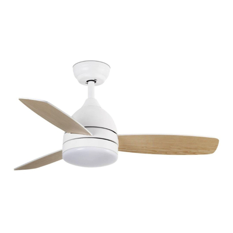
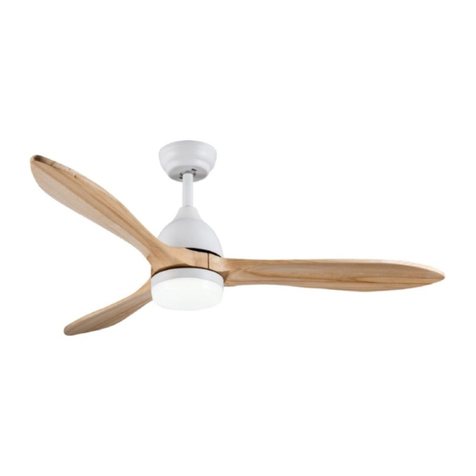
ventyly Hybrid VY25001 User manual

Assembly manual
Instrucciones de montaje
Manuel de montage
Ventyly Hybrid

EN. Congratulations on the purchase
of your new Ventyly fan that will pro-
vide you design, quality and comfort
for many years.
We are proud of our work and appre-
ciate the opportunity to provide one of
the best ceiling fans available.
It’s time to start enjoying your Ventyly
ceiling fan!
The manuals contain the complete
instructions for installing and operat-
ing with your fan safely. Remember to
tighten all screws firmly and make all
connections correctly.
FR. Félicitations pour l’achat de votre
nouveau ventilateur Ventyly qui vous
apportera design, qualité et confort
pendant de nombreuses années.
Nous sommes fiers de notre travail
et apprécions l’opportunité de fournir
l’un des meilleurs ventilateurs de
plafond disponibles.
Il est temps de commencer à profi-
ter de votre ventilateur de plafond
Ventyly!
Le manuel d’utilisation contient les
instructions complètes pour installer
et utiliser votre ventilateur en toute
sécurité. N’oubliez pas de serrer
toutes les vis fermement et de faire
toutes les connexions correctement.
ES. Felicidades por la compra de su
nuevo ventilador Ventyly que le pro-
porcionará diseño, calidad y confort
durante muchos años.
Estamos orgullosos de nuestro
trabajo y apreciamos la oportunidad
de suministrarle uno de los mejores
ventiladores de techo disponibles.
¡Toca empezar a disfrutar de su venti-
lador de techo Ventyly!
El manual de contiene las instruccio-
nes completas para instalar y operar
con su ventilador de forma segura.
Recuerde apretar firmemente todos
los tornillos y hacer todas las cone-
xiones correctamente.

②
1
6
2
5
43
1H 4H 8H
KIT
ON/OFF
Check list Lista de contenido Liste de contrôle
Bracket, Soporte,
Support de montage
Asseble kit, Kit de montaje
Assembler le kit
Remote control kit, Kit mando a
distancia, Kit de télécommande
Plate, Tapa
Plaque
Anti Swinging Kit
Kit Antibalanceo
Kit de anti balancement
Motor, Motor,
Moteur
(3) Blades, Palas,
Pales
a
g
f
h
b
c
d
** Support for kits, Soporte para kits,
Support pour kit
** note: only for ceiling fans with any additional kit
** nota: sólo para ventiladores con kit adicional
** remarque : uniquement pour les ventilateurs de
plafond avec tout kit supplémentaire
** Light kit, Kit de luz,
Kit d’éclairage
i
e
Light Kit, Kit de Luz, Kit d’Éclairage
ref. VY25106 (Black, Negro, Noir)
ref. VY25005 (White, Blanco, Blanc)
LED18W 2700K 800LM - 3500K 950LM - 4500K 900LM
This product contains a light source of energy efficiency class G
j

220-240
V
50/60
Hz
DC
motor RF
With Timer
1, 4, 8hr
Information Información Information
You will need Necesitarás Vous aurez besoin
1h
ref body blades
VY25001 White Alu White + Maple Plywood
VY25012 IOT White Alu White + Maple Plywood
VY25103 Black Alu Black + Walnut Plywood
VY25114 IOT Black Alu Black + Walnut Plywood

③
1.
2.
Assembly Montaje Montage
1 2
3 4
5 6
Disassemble Desensable
Démonter
Disassemble Desensable
Démonter
Install the fan bracket Instala el soporte del venti-
lador. Installez le support du ventilateur
Install the fan bracket Instala el soporte del venti-
lador. Installez le support du ventilateur
Install the fan bracket Instala el soporte del venti-
lador. Installez le support du ventilateur
Important!! ¡¡Importante!!
Important !
③
1.
2.

78
910
i
Assembly Montaje Montage
Connect the ceiling fan Conecta el ventilador
Connectez le ventilateur
Connect the receiver Conecta el receptor
Connectez le récepteur
Connect the receiver Conecta el receptor
Connectez le récepteur
Make the connections. Haz las conexiones. Si tienes dudas consulta a un técnico.
Faites les connexions. En cas de doute, consultez un technicien.
220-240V
N AC in neutral
L AC in live
L in earth

11 12
13 14
15 16
Assembly Montaje Montage
Motor cover. Cubierta del motor.
Capot moteur.
Motor cover. Cubierta del motor.
Capot moteur.
(6)
11.
12.
(6)
11.
12.
Motor cover. Cubierta del motor.
Capot moteur.
Blade assembly Monte las palas
Assemblage de la lame.
Loosen the screws. Aflojar los tornillos.
Desserrer les vis.
Tighten the screws. Aprieta los tornillos.
Serrer les vis.

(8)
15.
17
Assembly Montaje Montage
(9)
16.
1.
2.
3
Place the cover blades Coloca la cubierta de las
palas, Placez la couverture de Lames
Ventyly Hybrid
Without light kit Sin kit de luz
Sans kit d’éclairage
DONE!!!

(9)
16.
1.
2.
(9)
16.
1.
2.
(10)
3.
.
(10)
3.
.
18 with light kit
20 with light kit
19 with light kit
21 with light kit
Assembly Montaje Montage
(11)
5.
6.
(11)
5.
6.
Motor cover. Cubierta del motor.
Capot moteur.
Motor cover. Cubierta del motor.
Capot moteur.
DONE!!!
22 with light kit
3

Remote
Control Mando Dis-
tancia Télécom-
mande
1- Turn the ceiling fan off.
2- Ceiling fan speeds:
1 (the lowest) to 6 (the highest).
3- Light Dimmer.
4- Timer: The fan stops after 1h/4h/8h.
5- Vacation mode: switch on the light kit of
the ceiling fan 5 minutes each 2 or 3 hours.
6- Reverse function for winter & summer.
7- Breeze: The ceiling fan speeds automatic
cycle between 1 to 6 speeds.
8- Only for celing fans with kit.
EN
1- Apaga el ventilador.
2- Velicidades: 1 (la más baja) hasta 5 (la
más alta)
3- Regulación intensidad de la luz.
4- El ventilador funcionará durante 1h, 4h
o 8h.
5- Modo vacaciones: Enciende y apaga la
luz del ventilador durante 5 minutos cada
dos o tres horas.
6- Función inversa invierno-verano.
7- Función brisa: la velocidad de ventilador
cambia automáticamente pasando por las
seis velocidades.
8- Sólo para ventiladores con kit.
1- Éteignez le ventilateur.
2- Vitesses du ventilateur de plafond:
1 (le plus bas) à 5 (le plus élevé)
3- Variateur de lumière.
4- Avec Programmateur: le ventilateur s’ar-
rête après 1h / 4h / 8h.
5- Mode vacances: allumez le kit d’éclai-
rage du ventilateur de plafond 5 minutes
toutes les 2 ou 3 heures.
6- Fonction inverse pour l’hiver et l’été:
changer la direction du tour du ventilateur.
7- Fonction brise : la vitesse du ventilateur
change automatiquement tout en passant
par les six vitesses.
8- Uniquement pour les ventilateurs de
plafond avec kit.
FR
ES
3
1
2
4
3
5
6
7
8
2pcs x 1,5V AAA (no incl)
EN
ES
FR
Push to “O” for light kit accessory.
or “D” for other accessory
Pulsa a “O” para kit de luz
ó “D” para otros kits
Poussez sur «O» pour l’accessoire du kit d’éclairage
au sur «D» pour un autre accessoire O
D

Télécom-
mande
EN Light Dimmer.
ES Regula la intensidad de la luz.
FR Variateur de lumière.
EN Reverse Function.
ES Función inversa.
FR Fonction inverse.
EN Vacation mode.
ES Modo vacaciones.
FR Mode vacances.
Remote
Control Mando Dis-
tancia
3
2
2
3
Keep
pressed!!
Press
once
Press
once
Press
once
Keep
pressed!!
Press
once
②
1
6
2
5
43
1H 4 H 8H
KIT
ON/OFF
②
1
6
2
5
43
1H 4 H 8H
KIT
ON/OFF
②
1
6
2
5
43
1H 4 H 8H
KIT
ON/OFF
-+

Remote
Control Mando Dis-
tancia Télé
Comande
Off
Off
Off
On
2700K
On
3500K On
4500K
3
4 5
12
6
Information Informacion Information
7
For color change, press on/
off repeatedly. If the light is
off for more than 5 seconds,
the color will not be changed
when turning it back on.
Para cambiar el color de la
luz pulsa on-off repetida-
mente. Si la luz está apagada
más de 5 segundos el color
no habrá cambiado cuando
se vuelva a encender.
Pour le changement de
couleur, appuyez plusieurs
fois sur marche / arrêt. Si la
lumière est éteinte pendant
plus de 5 secondes, la
couleur ne sera pas modi-
fiée lors de la remise sous
tension.
②
1
6
2
5
43
1H 4 H 8H
KIT
ON/OFF
②
1
6
2
5
43
1H 4H 8H
KIT
ON/OFF
②
1
6
2
5
43
1H 4H 8H
KIT
ON/OFF
②
1
6
2
5
43
1H 4H 8H
KIT
ON/OFF
②
1
6
2
5
43
1H 4H 8H
KIT
ON/OFF
②
1
6
2
5
43
1H 4H 8H
KIT
ON/OFF
②
1
6
2
5
43
1H 4H 8H
KIT
ON/OFF
Press
once
Press
once
Press
once
Press
once
Press
once
Press
once

Warning Atención Attention
EN Read entire booklet carefully before begin-
ning installation and save these instructions.
Please contact our technical department with
any queries.
Always take into account all the specifications
of the appliance that figure on the grey label
stuck to the lamp and on the installation dia-
gram.
To avoid damage to finish, assemble motor on
soft padded surface or use the original foam
inset in motor box. Do not lay fan on its side as
this could result in shifting of motor in decora-
tive enclosure.
To reduce the risk of personal injury, attach
the fan directly to the support structure of the
building according to these instructions, and
use only the hardware supplied.
To avoid possible electrical shock, before in-
stalling your fan, disconnect the power by turn-
ing off the circuit breakers to the outlet box and
associated wall switch location.
For the electrical connection it is necessary to
incorporate an isolator switch according to the
installation regulations, which ensures all-pole
cut, directly connected to the power terminals
and it must have a contact separation in all its
poles, which provides total disconnection under
category III surge conditions.
All wiring and connections must be made in
accordance with national and local electrical
codes.The ceiling fan must be earthed in order
to prevent possible electric shock. If you are not
familiar with the way to do the electrical instal-
lation, you must use the services of a qualified
electrician.
Ensure that you don´t drill through electrical
wires or any other obstruction in the wall or
ceiling during installation. Electrical wiring may
never be clamped or twisted between the ceil-
ing fan support and the mounting surface.
Make sure that the fan is disconnected from the
mains before removing the protection.
To reduce the risk of personal injury, do not
bend the blade attachment the system when
installing, balancing or cleaning the fan. Nev-
er insert foreign objects between rotating fan
blades.
To reduce the risk of fire, electrical shock or
motor damage, do not lift or carry the fan by
the lead wires.
ATTENTION: If you notice an unusual oscillat-
ing movement of the fan, stop the fan immedi-
ately and contact the manufacturer, your ser-
vice agent or suitably qualified persons.
The assembly and replacement of the safe-
ty suspension system must be carried out by
the manufacturer, its agent or suitably qualified
persons.
The roof fixing system must support at least 4
times the weight of the fan.
The fan blades cannot be installed lower than
2,3m from the floor.
Do not install the ceiling fan on surfaces that
are moist, dreshly painted or electrically con-
ductive.
All ceiling fans without special protection
against dust or moisture (no IP rating) may be
used indoors, except in bathrooms.
The lights with LED modules should be posi-
tioned in such a way that they are not exposed
to direct sunlight or other sources of heat.
The important precautions, safeguards and
instructions appearing in this manual are not
meant to cover all possible conditions and sit-
uations that may occur. It must be understood
that common sense, caution and carefulness
are factors which cannot be built into this prod-
uct. These factors must be supplied by the per-
son(s) installing, caring for and operating the
unit.
Our fans comply with current safety regulations.
The internal or external manipulation of the
ceiling fan may reduce its safety. The manufac-
ture cannot be held liable for any manipulation
carried out by the user.
As our products are subject to technical mod-
ifications, we cannot guarantee, that all infor-
mation is always up to date. Please contact our
technical department with any queries.
Important
Nominal voltage (V) Difference of electrical po-
tential (voltage) between two points. This volt-
age must not exceed that marked on the fan.
Nominal frequency (Hz) Measures the number
of repetitions per unit of time (Hertz). This fre-
quency must not exceed the one marked on the
fan.
Current intensity (A-Ampere) is the flow of elec-
trical charge that travels through a material.
Nominal power (W) the maximum power that
the fan demands at different speeds, under nor-
mal conditions of use.
Number of turns (RPM) Of the fan depending
on the selected speed.

Air flow (CFM/m3min) Fan air flow
DC motor: The fan operates with direct current
at the same voltage (direct current). It is char-
acterized by: Its low consumption (up to 70%
less); Silent operation; An accurate control of
the speed; Speed for starting actions, accelera-
tion, deceleration and stoppage; Wide range of
speeds; it is lighter which facilitates the instal-
lation; it does not heat up.
INSTALLATION ADVICE
To get the most out of it and ensure the dura-
bility of your fan.
You must correctly choose the size of the fan
depending on the room where you will install it.
Respect the safety distance (2.3meters-90.50
inches) between the fan and surfaces, objects
or people nearby
The surface where you will install the fan and
the fixing bracket must be capable of supporting
4 times the weight of the fan (kilos - pounds).
In installations with more than one fan, ensure
the minimum distance of 2.30 meters between
the blades of the different fans.
As experts in ventilation, we recommend that
you install your fan at 2.30 meters high.
MAINTENANCE
Important! Before carrying out any mainte-
nance / revision task, make sure you have dis-
connected the electrical power from the main
circuit.
As fans tend to move during operation, some
connections may loosen. Check the supporting
screws, brackets and blade attachments twice
a year to ensure that they are secure.
There is no need to oil the motor as the bear-
ings are permanently lubricat.
Cleaning the fan helps to maintain its appear-
ance for years. Do not use water when clean-
ing. This could damage the motor or the blades
and could cause electrocution. Do not use dis-
solvents or abrasive substances. Use normal
neutral PH detergent.
Never clean the fan with pressure systems.
Use a soft brush or lint-free cloth to prevent
scratching the surface.
TROUBLE-SHOOTING GUIDE
Important! Before carrying out any mainte-
nance / revision task, make sure you have dis-
connected the electrical power from the main
circuit.
Ceiling fan do not start
1. Check the fuses and circuit breakers.
2. Review the connections of the terminal block
according to the indications in the installation.
3. Make sure that the sliding switch is firmly in
the position of up or down (when the ceiling fan
has it). The ventilator does not work when the
button is in the middle.
4. Make sure that you have removed the stabi-
lizing tongue-pieces of the motor.
5. Finally if the fan will not start call an electri-
cian. Do not attempt to touch the internal parts.
Ceiling fan sounds noisy
1. Check that the screws are are properly tight-
ened.
2. Check that canopy in assembled correctly.
3. llow at least 24 hours for the fan to settle, as
many noise will go away.
Optional light kit doens’t work.
Check the terminal connections are tight. If the
light is still not working contact an electrician.
The fan oscillates
1. Ensure the mounting bracket and canopy are
properly screws to the ceiling.
2. Verify that the space between the blades and
other objects is adequate.
3. Check the blades are securely fastened to
the holders and the blade holders are tight on
the motor.
4. Verify that the height of all the blades to the
roof is the same. If it detects that one is differ-
ent, place a washer, not supplied, between the
blade and the support, on the screw closest to
the motor, to adjust this distance. fig. 6
5. In case the incidence continues, use the an-
ti-roll kit provided, as follows:
On the shovel you notice the swing, with the
fan stopped, fix a clip (1) on the edge of the
blade, between the tip and the support. Start
the fan, to see if it has been fixed. Otherwise,
move the clip (1) towards the motor or towards
the end. Test until you find the position where
there is least balance. Once the best position
is located, place the weight (2) on the line
marked by the clip towards the centre of the
blade. Remember to remove the paper covering
the adhesive. This should correct the rolling.
Otherwise, repeat the process and add another
weigh.
Warning Atención Attention

Warning Atención Attention
SYMBOLOGY
RF
1- It has an earthing connection. The earth wire
(yellow / green) has to be connected to the clip
marked with.
2- It should only be installed in rooms where
direct contact with water is impossible.
3- The fan has the possibility of changing the
direction of rotation of the blades and thus op-
timize the movement of the air.
4- Remote control with radio frequency. It emits
waves to the receiver.
ES Lea todo este manual antes de empezar la
instalación y guarde estas instrucciones. En
caso de dudas, no dude en llamar a nuestro
departamento técnico.
Tenga en cuenta todas las especificaciones del
aparato que figuran en las etiquetas gris pega-
da en el ventilador y en la hoja del dibujo de
instalación.
Para no dañar las superficies de la carcasa,
monte el motor sobre una superficie blanda o
utilice la espuma suministrada en el embala-
je. No apoye el motor de lado, ya que podría
dañarlo.
Para reducir el riesgo de lesiones personales,
fije el ventilador directamente a la estructura
de soporte del edificio de acuerdo con estas
instrucciones y use solamente los herrajes
suministrados.
Para evitar un posible choque eléctrico, antes
de instalar su ventilador desconecte la elect-
ricidad, apagando los interruptores de circuito
o disyuntores que alimentan la caja eléctrica
donde se va a instalar al ventilador y el inter-
ruptor de pared asociado.
Para la conexión eléctrica es preciso incorporar
un interruptor seccionador de acuerdo con las
reglamentaciones de instalación, que asegure
el corte omnipolar, directamente conectado a
los bornes de alimentación y debe tener una
separación de contacto en todos sus polos, que
suministre desconexión total bajo condiciones
de sobretensión de categoría III.
Todos los procedimientos de conexión eléctri-
ca e instalación deben cumplir con los códigos
eléctricos nacionales y códigos locales. El ven-
tilador de techo debe estar conectado a tierra
a fin de prevenir posibles descargas eléctricas.
La instalación eléctrica debe ser llevada a cabo
o aprobada por un electricista autorizado.
Asegúrese de no dañar el cableado eléctrico
de la red al taladrar el techo. Los cables eléctri-
cos no se pueden nunca torcer o grapar entre
el ventilador y la superficie de soporte.
Asegurarse de que el ventilador está de-
sconectado de la alimentación antes de quitar
la protección.
Para reducir el riesgo de lesiones personales,
no doble el sistema de fijación de las palas
cuando instale, equilibre o limpie el ventilador.
Nunca inserte objetos extraños entre las palas
del ventilador cuando este girando.
Para reducir el riesgo de incendio, choque
eléctrico o daños al motor, no levante ni car-
gue el ventilador sosteniéndolo por los cables
eléctricos.
ATENCIÓN: Si detecta un movimiento insólito
oscilante del ventilador, pare el ventilador in-
mediatamente y póngase en contacto con el
fabricante, su agente de servicio o personas
adecuadamente calificadas.
El montaje y reemplazo del sistema de sus-
pensión de seguridad debe ser realizado por
el fabricante, su agente o personas adecuada-
mente calificadas.
El sistema de fijación al techo deberá soportar
como mínimo 4 veces el peso del ventilador.
Las palas del ventilador no pueden quedar a
una altura menor de 2,30m / 7.54 pies sobre
el suelo.
No monte el ventilador sobre superficies húme-
das, recién pintadas o que presenten conduc-
tividad eléctrica.
Las luminarias sin protección especial contra
la penetración de polvo o humedad (sin marca
IP) sólo son aptas para uso en interior, donde
el contacto con el agua y la humedad sea im-
posible.
Las luminarias con módulos LED deben posi-
cionarse de tal manera que no estén expuestos
fuentes de calor.
Las instrucciones y las normas de seguridad
contenidas en el presente manual no pueden
prevenir todas las condiciones y situaciones
que pudieran presentarse. Por razones obvias,
el presente manual no puede incluir factores
como la precaución y el cuidado. Estos factores
deberán ser asumidos por la(s) persona(s) que

instalan, mantienen y utilizan el producto.
Nuestros ventiladores cumplen con las normas
de seguridad vigentes.
La manipulación interna o externa de la lu-
minaria puede comprometer su seguridad. El
fabricante no asume las responsabilidades
derivadas del uso, manipulación y montaje in-
correctos realizados por el usuario.
Nuestros productos están sujetos a cambios
técnicos u optimizaciones, por ello no nos re-
sponsabilizamos que toda la información técni-
ca este actualizada. En caso de preguntas, no
dude en llamar a nuestro departamento técnico.
Importante
Tensión nominal (V): diferencia de potencial
eléctrico (voltaje) entre dos puntos. Esta ten-
sión no debe superar la marcada en el venti-
lador.
Hz: Frecuencia nominal mide el número de
repeticiones por unidad de tiempo (Hercio).
Esta frecuencia no debe superar la marcada en
el ventilador.
Intensidad de la corriente (A-Amperio) es el flu-
jo de carga eléctrica que recorre un material.
Potencia nominal (W) es la potencia máxima
que demanda el ventilador a las diferentes vel-
ocidades, en condiciones de uso normales.
Número de giros del ventilador dependiendo de
la velocidad seleccionada (RPM).
Air flow (CFM/ m3min) Flujo de aire del ven-
tilador
DC motor: El ventilador funciona a corriente
continua, a la misma tensión (corriente direc-
ta).Se caracteriza por su bajo consumo (has-
ta 70%menos), funcionamiento silencioso, un
control preciso de la velocidad, rapidez para las
acciones de arranque, aceleración, desacel-
eración y paro, amplio rango de velocidades,
és más ligero y eso facilita la instalacióny no
se calienta.
CONSEJOS DE INSTALACIÓN
Para sacar el máximo partido y garantizar la
durabilidad de su ventilador debe elegir cor-
rectamente el tamaño del ventilador en función
de la habitación donde lo vaya a instalar, respe-
tar la distancia de seguridad (2,3m-90.50inch-
es) entre el ventilador y las superficies, objetos
o personas cercanas.
La superfície donde va a instalar el ventilador y
el soporte de fijación debe ser capaz de sopor-
tar 4 veces el peso de este (kilos - libras).
En instalaciones de más de un ventilador ase-
gure la distancia mínima de 2,30 metros entre
las aspas de los diferentes ventiladores.
MANTENIMIENTO
Importante! Antes de realizar cualquier tar-
ea de mantenimiento asegúrate que has de-
sconectado la corriente eléctrica desde el cir-
cuito principal.
Debido al movimiento natural del ventilador,
algunas conexiones podrían soltarse. Revisa
las conexiones, los soportes y las fijaciones de
las palas dos veces al año para asegurar que
siguen firmes.
No es necesario engrasar el ventilador. El mo-
tor tiene rodamientos lubricados permanente-
mente.
El ventilador se tiene que limpiar con un paño
suave y húmedo, evitando el contacto de líqui-
dos con las partes eléctricas. Utiliza un deter-
gente de pH neutro.
Nunca limpies el ventilador con sistemas a
presión.
Utiliza solamente un paño suave para evitar ra-
yar el acabado.
GUÍA DE LOCALIZACIÓN DE AVERÍAS
Importante! Antes de realizar cualquier revisión
asegúrate que has desconectado la corriente
eléctrica desde el circuito principal
El ventilador no arranca
1. Revisa los circuitos principales y secundari-
os, asegúrate que están encendidos.
2. Revisa las conexiones en el bloque de termi-
nales según lo indicado en la instalación.
3. Asegura que has quitado las lengüetas esta-
bilizadoras del motor.
4. Si el ventilador todavía no funciona, llama a
un electricista cualificado. No trates de reparar
las conexiones eléctricas internas sin tener ex-
periencia para hacerlo.
El ventilador hace ruido
1. Asegura que todos los tornillos están apre-
tados.
2. Comprueba que el embellecedor esté bien
colocado, tocando al techo.
3. Permite un periodo de asentamiento de 24
horas. La mayoría de los ruidos asociados con
un ventilador nuevo desaparecen después de
este periodo.
La luz no se enciende (cuando hay kit de luz)
Revisa las conexiones del kit de luz. Si el kit
de luz todavía no funciona, pide ayuda a un
electricista cualificado.
El ventilador se balancea
Warning Atención Attention

Warning Atención Attention
1. Asegúrate que la bola de suspensión del ven-
tilador está bien asentada y que los soportes
de montaje estén firmemente apretados a la
viga del techo.
2. Verifica que el espacio entre las palas y otros
objetos es el adecuado.
3. Revisa que todos tornillos están bien apreta-
dos. Confirma que los soportes de las palas y
las palas están correctamente colocados.
4. Verifica que la altura de todas las palas al
techo es la misma. Si detecta que alguna es
diferente coloca una arandela, no suministra-
da, entre la pala y el soporte, en el tornillo más
cercano al motor, para ajustar esta distancia.
5. Si aún así no se ha corregido el balanceo,
intercambia dos palas adyacentes para redis-
tribuir el peso. El funcionamiento será más
suave.
6. En caso de que continúe la incidencia, uti-
liza el kit anti-balanceo que se suministra, de
la siguiente manera:
En la pala que notas el balanceo, con el ven-
tilador parado, fija una grapa (1) en el borde
de la pala, entre la punta y el soporte. Pon en
marcha el ventilador, para ver si se ha solucio-
nado. En caso contrario desplaza la grapa (1)
hacia el motor o hacia a punta. Prueba hasta
que encuentres la posición donde haya menos
balanceo. Una vez localizada la mejor posición
coloca el peso (2) en la línea que te marca el
clip hacia el centro de la pala. Recuerda quitar
el papel que cubre el adhesivo. Esto debería
corregir el balanceo. En caso contrario repite el
proceso y añade otro peso.
SIMBOLOGIA
RF
1- Toma de tierra (cable amarillo/verde) que
debe ser conectado al clip marcado con el
símbolo.
2- Ventilador de uso exclusivo para interiores,
en habitaciones donde el contacto con el agua
y la humedad sea imposible.
3- Comandament a distància amb ràdio fre-
qüència. Emet ones al receptor.
4- Función Inversa: El ventilador tiene la posi-
bilidad de cambiar la dirección de rotación de
las palas y así optimizar el movimiento del aire.
FR Lisez tout ce manuel soigneusement avant
de commencer l’installation et gardez ces in-
structions. Notre service technique se tient à
votre entière disposition pour toute information.
Veuillez toujours prendre en compte toutes les
spécifications de l’appareil figurant sur l’éti-
quette grise collée sur la lampe et sur le docu-
ment du schéma d’installation.
Sortez le moteur du carton d’emballage. Pour
éviter de rayer la finition, assemblez le moteur
sur une surface douce matelassée ou utilisez
la mousse du boîtier moteur. Ne posez pas le
ventilateur sur le côté pour ne pas détériorer la
finition décorative.
Pour réduire le risque de lésions personnelles,
fixez le ventilateur directement à la structure de
support de la maison ou du bâtiment en accord
avec ces instructions et utilisez seulement les
pièces fournies.
Pour éviter un possible choc électrique, avant
l’installation du ventilateur arrêtez l’alimenta-
tion électrique en enlevant les fusibles ou en
interrompant les disjoncteurs.
Pour la connexion électrique, il est nécessaire
d´incorporer un interrupteur sectionneur selon
les réglementations d´installation, qui assure
la coupure omnipolaire, directement connecté
aux bornes d´alimentation et il doit y avoir une
séparation de contact à tous les pôles. Celui-ci
approvisionne le débranchement total sous des
conditions de surtension de catégories III.
Tout le câblage et les connexions doivent être
en accord avec les codes électriques nationaux
et locaux. Le ventilateur de plafond doit être
relié à la terre afin d’éviter tout risque d’élec-
trocution. Si vous ne savez pas bien comment
faire l´installation électrique, il faudra utiliser
les services d´un électricien qualifié.
Assurez-vous que vous ne percez pas de trous
au milieu de réseaux câblés existants (dans
les murs ou plafonds) lorsque vous installez
un équipement. Adaptez la longueur des fils
de votre installation afin d’éviter la torsion et
l’écrasement des fils.
Assurez-vous que le ventilateur est débranché
avant d´enlever la protection.
Pour réduire le risque d’incendie, de choc élec-

trique ou de blessure personnelle, ne pas plier
les supports de pale lors de l’installation des
supports, de l’équilibrage des pales ou du net-
toyage du ventilateur. Ne pas insérer de corps
étranger entre les pales du ventilateur en mou-
vement.
ATTENTION: Si vous remarquez un mouve-
ment oscillant inhabituel du ventilateur, ar-
rêtez-le immédiatement et contactez le fabri-
cant, votre agent de service ou des personnes
dûment qualifiées.
Le montage et le remplacement de la suspen-
sion de sécurité doivent être effectués par le
fabricant, son agent ou des personnes dûment
qualifiées.
Le système de fixation du toit doit supporter au
moins 4 fois le poids du ventilateur.
Les pales du ventilateur doivent être à une hau-
teur d’au moins 2,3m du sol.
Ne pas monter le ventilateur sur une surface
humide, récemment peinte ou présen-tant une
forte conductivité electrique.
Les luminaires sans protection particulière con-
tre la poussière (sans marquee IP) sont aptes
à une utilisation en intérieur, à l’exception des
salles de bains.
Les luminaires avec modules LED doivent être
positionnés de sorte qu’ils ne soient pas ex-
posés à la lumière directe du soleil ou d’autres
sources de chaleur.
Les précautions, mises en garde et consignes
importantes contenues dans ce manuel ne sont
pas destinées à couvrir toutes les conditions
et situations qu’il est possible de rencontrer.
Il faut bien comprendre que le bon sens, la
prudence et l’attention sont des notions qui
ne peuvent être comprises dans cet appareil.
Ces notions doivent être utilisées par la(les)
personne(s) qui installent, entretiennent et uti-
lisent cet appareil.
Nos ventilateurs sont conformes aux normes
de sécurité en vigueur.
La manipulation interne ou externe du lumi-
naire peut compromettre votre sécurité. Le fab-
ricant n’est pas responsable des manipulations
réalisées par l’utilisateur.
Nos produits sont susceptibles d’être modifiés
techniquement ou optimisés. Par conséquent,
nous ne pouvons pas garantir que toutes les
informations de cette fiche technique soient à
jour. Notre service technique se tient à votre
entière disposition pour toute information.
Important
Tension nominale (V) Différence de potentiel
électrique (tension) entre deux points. Cette
tension ne doit pas dépasser celle indiquée sur
le ventilateur.
Fréquence nominale (Hz) Mesure le nombre de
répétitions par unité de temps (Hertz). Cette
fréquence ne doit pas dépasser celle indiquée
sur le ventilateur.
Intensité du courant (A-Ampère): flux de charge
électrique qui traverse un maté-riau.
Puissance nominale (W) Représente la puis-
sance maximale requise par le ventilateur à
différentes vitesses, dans des conditions nor-
males d’utilisation.
Nombre de tours (RPM) du ventilateur en fonc-
tion de la vitesse sélectionnée.
Air flow (CFM/ m3min) Débit d’air du ventilateur
DC motor : Le ventilateur fonctionne en courant
continu, à la même tension (courant continu).
Se caractérise par: sa faible consommation
(jusqu’à 70% de moins); Opération silencieuse;
Un contrôle précis de la vitesse; Vitesse
pour les actions de démarrage, accélération,
décélération et arrêt; Large gamme de vitess-
es; c’est plus léger et cela facilite l’installation.
Ne chauffe pas.
CONSEILS D’INSTALLATION
Pour en tirer le maximum et assurer la dura-
bilité de votre ventilateur, vous devez choisir
correctement la taille du ventilateur en fonc-
tion de la pièce dans laquelle vous allez l’in-
staller, respectez la distance de sécurité
(2.3mètres-90,50 pouces) entre le ventilateur
et les surfa-ces, objets ou personnes à prox-
imité.
La surface sur laquelle vous allez instal-ler le
ventilateur et le support de fixation doit pouvoir
supporter 4 fois son poids (kilos - livres).
Dans les installations avec plusieurs ventila-
teurs, veillez à respecter une distance minimale
de 2,30 mètres entre les pales des différents
ventilateurs.
MAINTENANCE
ATTENTION ! Avant d’effectuer toute tâche de
maintenance / révision, assurez-vous d’avoir
débranché l’alimentation électrique du circuit
principal.
En raison du mouvement naturel du ventilateur,
certaines connexions peuvent se desserrer.
Vérifier les connexions du support, les sup-
ports et les fixations de pale deux fois par an.
Warning Atención Attention

Warning Atención Attention
S’assurer qu’elles soient fermement serrées.
Inutile d’huiler votre ventilateur. Le moteur a
des roulements lubrifiés à vie.
Nettoyez périodiquement le ventilateur pour
bien préserver son aspect au fil des ans. Ne
pas nettoyer à l’eau. Ceci pourrait endommager
le moteur, ou le bois ou même causer une élec-
trocution. Veuillez ne pas utiliser de solvants
ou de substances abrasives. Veuillez utiliser un
détergent courant au PH neutre.
Ne jamais nettoyer le luminaire avec des sys-
tèmes à pression.
N’utiliser qu’une brosse souple ou un chiffon
non pelucheux pour éviter de ra-yer le fini.
GUIDE DE DÉPANNAGE
ATTENTION ! Avant d’effectuer toute tâche de
maintenance / révision, assurez-vous d’avoir
débranché l’alimentation électrique du circuit
principal.
Le ventilateur ne démarre pas
1. Vérifier le fusible principal et les fusibles sec-
ondaires ou les disjoncteurs.
2. Vérifier les connexions de la planche à
bornes. Veuillez toujours prendre en compte le
document du schéma d’installation.
3. S’assurer que les languettes de blocage pour
l’expédition aient été retirées du moteur.
4. Si le ventilateur ne démarre toujours pas,
contacter un électricien qualifié. Ne pas essay-
er de réparer les connexions électriques soi-
même.
Le ventilateur fait trop de bruit
1. Vérifier que toutes les vis sont serrées.
2. S’assurer que la calotte et le support de fixa-
tion soient fermement fixés au plafond.
3. Compter une période de rodage de 24 heu-
res. La plupart des bruits associés à un nou-
veau ventilateur disparaissent au bout de ce
temps.
Si le luminaire ne fonctionne pas
Vérifier que le connecteur molex du boî-tier
de commutateur soit connecté. Si l’ensemble
d’éclairage ne fonctionne tou-jours pas, con-
tacter un électricien qualifié.
Le ventilateur oscille
1. Assurez-vous que l’embellisseur soit bien
placé, touchant le plafond.
2.Vérifiez que l’espace entre les pales et les
autres objets est adéquat.
3. Vérifier que toutes les pales sont fermement
vissées dans les supports de pale. Vérifier
que tous les supports de pale sont fermement
vissés sur le moteur.
4. La plupart des problèmes d’oscillation de
ventilateur sont causés par des inégalités de
niveaux de pales. Vérifier ce niveau en choisis-
sant un point sur le plafond au-dessus de l’ex-
trémité de l’une des pales. Insérer une rondelle
(non fournie) entre la pale et le support de pale
à la vis la plus proche du moteur.
5. Si les oscillations de pale se voient encore,
échanger deux pales adjacentes pour redis-
tribuer le poids et éventuellement entraîner un
fonctionnement sans à-coup.
6. Si l’incidence persiste, utilisez le kit an-
ti-oscillation fourni comme suit: Sur la pale où
vous remarquez le mouvement, avec le venti-
lateur arrêté, fixez un clip (1) sur le bord de la
pale, entre la pointe et le support. Démarrez
le ventilateur pour voir s’il a été corrigé. Si-
non, déplacez le clip (1) vers le moteur ou vers
l’extrémité de la pale. Testez jusqu’à trouver la
position où il y a le plus d’équilibre. Une fois
que la meilleure position est trouvée, placez le
poids (2) sur la ligne marquée par le clip vers
le centre de la pale. N’oubliez pas de retirer
le papier recouvrant l’adhésif. Cela devrait cor-
riger l’oscillation. Sinon, répétez le processus
et ajoutez un autre poids.
SYMBOLES
RF
1- L’équipement a une connexion à la prise de
terre. Le câble de terre (jaune/vert) doit être
connecté au clip marqué.
2- Cet appareil peut être installé dans des
pièces à l’intérieur et à l’extérieur.
3- Fonction Inverse: Le ventilateur a la possibil-
ité de changer le sens de rotation des pales et
ainsi d’optimiser le mouvement de l’air.
4- Télécommande avec fréquence radio. Celle-
ci émet des ondes vers l’apareil récepteur.

EN In Compliance with General Law 23/2003 &
R.D.L. 1/2007.
If any of the parts of your ceiling fan is faulty at
any moment within the 2 year period since its pur-
chase date due to an original material defect or
manufacturing, the replacing of the part or its re-
pair will be completely free of charge
If the reparation should fail to satisfy the custom-
er and/or the object fail to present the optimum
condition for the use to which it is destined the
guarantee holder will have the right to the substi-
tution of the acquired item for another of identical
characteristics.
Do not install the product if it is damaged. This
lighting was properly packed in such a way that
its smaller parts could not get damaged during its
transport. Inspect everything to confirm that noth-
ing was damaged.
We reserve the right our specialists to study each
product returned, leaving the warranty exempt in
case of demonstrating that the incidence or failure
has been caused by the user, due to installation
problems or elements unrelated to the product.
A representative of the manufacturer will have ac-
cess to the defective products.
This warranty does not cover labour costs for the
disassembly of the Products.
If the manufacturer chooses to replace a defective
product but cannot do so, because it is not man-
ufactured or is no longer available, the manufac-
turer may replace the product with a comparable
product (whose design or specifications may vary
slightly). The replacement will be efective only for
the damaged unit.
This limited warranty shall only be valid when the
product has been properly installed, connected
and is functioning with the correct electrical val-
ues, operating range and at the environmental
conditions set forth in the technical specifications,
according to the guidelines, instructions, IEC
standards or any other document supplied with
the Products.
The manufacturer is not responsible for the elec-
trical power supply conditions, including the volt-
age surges, the voltage fluctuations, the control
systems for power waving that exceed the speci-
fied limits of the products and those defined in the
relevant supply rules.
This warranty is not valid for damages or malfunc-
tions due to force majeure or any type of fraudu-
lent, incorrect use, misuse, anomalous use or use
that violates the rules, codes or the corresponding
instructions of use, including without limitation the
contents regarding the latest safety rules, as well
as the latest industry and/or electricity regulations
in the relevant regions.
The maintenance of the product must be carried
out according to the instructions and by special-
ized personnel only.
An adequate record of the operating history must
be kept at the disposal of the manufacturer to be
inspected at any moment.
If it is determined that a product is defective or
does not function in accordance with the product
specifications, the buyer must notify the manufac-
turer in writing.
All warranty periods mentioned are subject to a
representative of the manufacturer being able to
access the defective product or system to check
such non-conformity. The warranty claims must be
notified and sent to the manufacturer’s regional
office within 30 days of such indication, and at
least the following information must be specified
(additional information may be requested):
- Defective products. For the guarantees of a Sys-
tem, other components that are used must also
be specified.
- Date of installation and invoice date.
- A detailed description of the problem, the amount
and the percentage of malfunctions, together with
the fault date code.
- The application, the functioning hours and
switching cycles.
- When the warranty claim is justified, the manu-
facturer shall bear the transportation costs. The
manufacturer may invoice to the client the re-
turned products that are not defective or noncon-
forming, together with the associated transporta-
tion, verification and handling expenses.
This warranty does not cover:
- Any exposure to corrosive environments or ag-
gressive gases of chemical origin.
- Negligent, improper or inappropriate use.
- Use of the product at a different environmental
temperature than the one specified.
- In LED light sources, faults smaller than 0.2%
for every 1000h.
- Decrease of luminous flux of less than 30% in
LED light sources.
- Relative humidity in the installation above 80%,
or if the conditions have been exceeded according
to the IP rating of the product for which it was
designed.
ES Cumpliendo con la Ley 23/2003, R.D.L. 1/2007.
Si alguna pieza de su ventilador de techo fallara
en cualquier momento dentro del período de 2
años desde la fecha de compra debido a un de-
fecto originario de los materiales o de fabricación,
procederemos a su reparación o a la reposición
Guarantee Garantia Garantie
This manual suits for next models
3
Table of contents
Other ventyly Fan manuals

ventyly
ventyly Kibo VT22001 User manual

ventyly
ventyly KOMET User manual

ventyly
ventyly VY26100 User manual

ventyly
ventyly Neat VT23103 User manual

ventyly
ventyly Aneto VT007 User manual

ventyly
ventyly KAMET VT23101 User manual

ventyly
ventyly Fluid VT22208 User manual

ventyly
ventyly Oxygen VT23201 User manual
Popular Fan manuals by other brands

Broan
Broan sensaire hs130 instruction manual

ebm-paps
ebm-paps K3G400-PA27-62 operating instructions

HAMPTON BAY
HAMPTON BAY SINCLAIR 798-072 Use and care guide

Kichler Lighting
Kichler Lighting Cottage Grove instruction manual

Fanimation
Fanimation Draco FP3220CH Specification sheet

Canarm
Canarm AXIS installation instructions