Venue Lighting Effects revolver laser User manual

revolver laser
DUAL-SIDED MOVING HEAD EFFECT LIGHT
WITH LASER AND MOONFLOWER
www.venuelightingeffects.com


3
www.venuelightingeffects.com
INTRODUCTION
The Venue Revolver Laser is a DMX intelligent, dual sided, moving head effect
light, which includes both a laser and moonflower effect. It is lightweight and
compact which makes it a great light for mobile DJs, clubs and parties. This unit
can be used as a standalone fixture in sound-activated mode, or controlled via
DMX controller.
TABLE OF CONTENTS
BEFORE YOU BEGIN 4
What is included 4
Unpacking Instructions 4
Manual Conventions 4
Icons 4
SAFETY INSTRUCTIONS 5
INTRODUCTIONS 6
Control Features 6
Additional Features 6
Control Panel 6
SETUP 7
AC Power 7
Back Panel 7
Mounting Orientation 8
Rigging 8
Signal Linking 9
OPERATING INSTRUCTIONS 9
Control Panel Buttons 9
Menu Map 10
STANDALONE OPERATION 12
Automatic 12
Sound-active 13
Audio sensitivity 13
Custom static colors/
Manual Control 13
DMX OPERATION 13
Configuring the Starting Address 14
Master/Slave
(Standalone Operating Modes) 14
11-Ch mode DMX operation 15
17-Ch mode DMX operation 15
DMX Parameters 16
APPENDIX 18
DMX Primer 18
General Troubleshooting 18
Fixture Linking 19
DMX Data Cable 19
Cable Connectors 19
3-Pin to 5-pin Conversion Chart 20
Setting Up a DMX Serial Data Link 20
General Maintenance 20
TECHNICAL SPECIFICATIONS 21
WARRANTY 22

4Venue Revolver Laser Manual
BEFORE YOU BEGIN
• Revolver Laser
• Mounting Bracket
• Mounting Bolts (x2)
•13mm Safety Loop
• Power Cord
• User Manual
What Is Included
Unpacking Instructions
Carefully unpack the carton, then check the contents to ensure that all parts are
present and have been received in good condition. Notify the shipper immediately
and retain packing material for inspection if any parts appear damaged from
shipping, or the carton itself shows signs of mishandling. Save the carton and all
packing materials. In the event that a fixture must be returned to the factory, it is
important that the fixture be returned in the original factory box and packing.
Manual Conventions
Venue® manuals use the following conventions to differentiate certain types of
information from the regular text.
CONVENTION MEANING
<Menu> Key to be pressed on the fixture’s Control Display
1~512 Range of values
50/60 Set of values of which only one can be chosen
Settings Menu option not to be modified (for example, showing the
operating mode/current status)
MENU > Settings Sequence of menu options to be followed
ON Value to be entered or selected
Icons
This manual uses the following icons to indicate information that requires special
attention on the part of the user.
ICONS MEANING
This paragraph contains critical installation, configuration or operation
information. Failure to comply with this information may render the fixture partially
or completely inoperative, cause damage to the fixture or cause harm to the user.
This paragraph contains important installation or configuration information.
Failure to comply with this information may prevent the fixture from
functioning correctly.
This paragraph reminds you of useful, although not critical, information.

5
www.venuelightingeffects.com
SAFETY INSTRUCTIONS
Please read these instructions carefully. It includes important
information about the installation, usage and maintenance of
this product.
FCC Statement
1. This device complies with Part 15 of the FCC Rules. Operation is subject to the following two conditions:
(1) This device may not cause harmful interference, and
(2) This device must accept any interference received, including interference that may cause undesired
operation.
2. Changes or modifications not expressly approved by the party responsible for compliance could void
the user’s authority to operate the equipment.
NOTE: This equipment has been tested and found to comply with the limits for a Class B digital device,
pursuant to Part 15 of the FCC Rules. These limits are designed to provide reasonable protection against
harmful interference in a residential installation.
This equipment generates, uses, and can radiate radio frequency energy and, if not installed and used in
accordance with the instructions, may cause harmful interference to radio communications. However,
there is no guarantee that interference will not occur in a particular installation. If this equipment does
cause harmful interference to radio or television reception, which can be determined by turning the
equipment off and on, the user is encouraged to try to correct the interference by one or more of the
following measures:
Reorient or relocate the receiving antenna.
Increase the separation between the equipment and receiver.
Connect the equipment into an outlet on a circuit different from that to which the receiver is connected.
Consult the dealer or an experienced radio/TV technician for help.
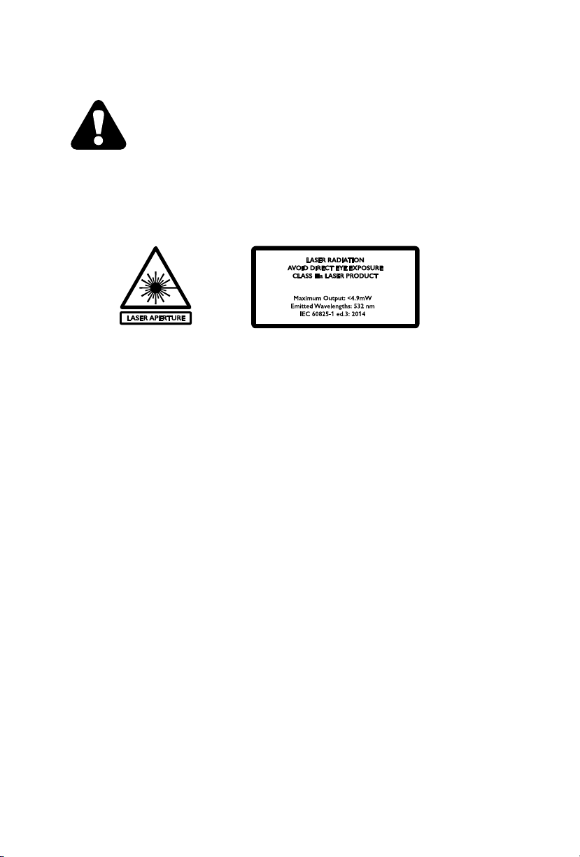
Laser Warning
The arrow indicates the laser aperture.
AVOID EXPOSURE – LASER RADIATION IS EMITTED FROM THIS APERTURE
Use extreme caution when the laser beam is turned on. When device is in use, do NOT look directly or
indirectly (reflectance) into the laser beam. NEVER point the laser beam directly or via a reflecting surface
towards another people’s or animals’ eyes or skin. Burns and permanent eye damage will result.
Do not point the laser beam towards highly explosive gasses.
Keep out of reach of children.

6Venue Revolver Laser Manual
INTRODUCTIONS
Control Features
• Dual-sided moving head, with laser and moonflower effects
• Static colors and RGBW color mixing with or without DMX controller
• 540° pan control and unlimited tilt control, with or without DMX controller
• Built-in automated programs via master/slave or DMX with variable speed
• Built-in sound activated programs via master/slave or DMX
• 11, 13, and 17 channel DMX-512 operation
Additional Features
• Includes rubber feet for desktop placement & metal bracket/safety loop for truss mounting
Control Panel
General Safety
• Please keep this User Manual for future reference.
• Make sure that you are connecting to the proper voltage, and that the line voltage you are connecting
to is not higher than that stated on the decal or rear panel of the fixture.
• This product is intended for indoor use only! To prevent risk of fire or shock, do not expose fixture
to rain or moisture.
• Make sure there are no flammable materials close to the unit while operating.
• The unit must be installed in a location with adequate ventilation, at least 20” (50 cm) from adjacent
surfaces. Be sure that no ventilation slots are blocked.
• Always disconnect from the power source before servicing or replacing the fuse and be sure to
replace with same type fuse.
• Secure fixture to included safety loop using a safety chain.
• Maximum ambient temperature is 104° F (40° C). Do not operate the fixture at temperatures
higher than this.
• In the event of a serious operating problem, stop using the unit immediately. Never try to repair
the unit yourself.
• Never connect the device to a dimmer pack.
• Make sure the power cord is never crimped or damaged.
• Never disconnect the power cord by pulling or tugging on the cord.
• Never carry the fixture directly from the cord. Always use the hanging/mounting bracket.
• Avoid direct eye exposure to the light source while it is on.

7
www.venuelightingeffects.com
SETUP
This fixture runs on 100~240 VAC, 50/60 Hz. Before powering on the unit, make sure the line voltage is
within the range of accepted voltages.
To determine the power requirements for a particular fixture, see the label affixed to the bottom of the
fixture or refer to the fixture’s specifications chart. A fixture’s listed current rating indicates its average
current draw under normal conditions.
AC Power
Always connect the fixture to a switched circuit. Never connect the fixture to a rheostat
(variable resistor) or dimmer circuit, even if the rheostat or dimmer channel is used only
as a 0 to 100% switch.
Always connect the fixture to a circuit with a suitable electrical ground.
Back Panel

8Venue Revolver Laser Manual
Mounting Orientation
The Revolver Laser includes a metal bracket and safety loop for hanging upside-down only.
Rigging
Be sure that the structure can support the weight of the fixture. Please see the “Technical Specifications”
section of this manual for a detailed weight listing. Mount the fixture securely. This may be done with a
screw, nut and bolt, or a hanging clamp (not included). The hole in each bracket can fit a 13mm screw or
bolt. When rigging, consider routine maintenance and back panel access. Please see the following steps
for installation.
• Ensure that cables are neatly organized and sufficient space is provided to allow full movement
of the fixture.
• There are rubber feet attached to the base, which may be used primarily for floor or desk
standing positions.
• Safety cables must always be used.
Lighting clamp
not included.
Safety cables must
always be used in
conjunction with the
included Saety Loop

9
www.venuelightingeffects.com
Signal Linking
In order to use this fixture in a DMX or master/slave operation, you must daisy chain using DMX cables to
link from one fixture to another.
OPERATING INSTRUCTIONS
Access these functions using the four buttons located directly underneath the LED Control Display.
Control Panel Buttons
BUTTON FUNCTION
<Menu> Scrolls through the current operating mode, as well as back
out of the current menu option
<UP> Selects increasing advancement in the value
<DOWN> Selects decreasing advancement in the value
<ENTER> Selects a value and stores it to memory

10 Venue Revolver Laser Manual
The Control Display shows the current state of the unit. It is used to select the operating mode, as well as
the sub-features. For detailed functions, please see the section below.
MAIN FUNCTION SUB-
FUNCTION SELECTION INSTRUCTION
DMX Address Addr 1-512 Select starting DMX address
Channel Mode ChNd
11CH
Select between 11-channel, 13-channel,
and 17-channel DMX modes.
13CH
17CH
Master/Slave
Mode SLNd
NASt Designate as the master unit
SL1 Designate as slave unit
SL2
Designate as slave unit in random mode,
switches between slave and Auto Program
Scene/Program ShNd
SH 0
Select pre-programmed
chase 0 - 10
SH 1
SH 2
SH 3
SH 4
SH 5
SH 6
SH 7
SH 8
SH 9
SH 10
Auto Mode Auto
On Enable or disable automatic
movement sequence and must
be switched to “OFF” for
Sound Active Mode
Off
Sound Active SoUn
On Enable or disable sound-active mode,
Auto Mode must be turned “OFF”
for Sound Active mode
Off
Audio
Sensitivity Sens 0–100
Select sensitivity level of the microphone
between 0 (less sensitive) and
100 (more sensitive).
Pause Mode bLNd
Yes Pause current program (Blackout)
No Resume program
Control Panel Menu Selections

11
www.venuelightingeffects.com
MAIN FUNCTION SUB-
FUNCTION SELECTION INSTRUCTION
Dimming dINd
Stda Select “Standard” dimming mode
StGE Select “Stage” dimming mode
tv Select “TV” dimming mode
ArAL Select “Architectural” dimming mode
tHAL Select “Theatrical” dimming mode
Pan Turn PInt
No Select standard or reverse
X-axis movement
Yes
Tilt Turn tInt
No Select standard or reverse
Y-axis movement
Yes
Led Display Led
On Select whether the LED display
will always be illuminated.
Off
Flip Display dISP
When this menu option is selected,
the display will instantly flip upside-
down, for better visibility when
hanging from a truss.
Test teSt
When this menu option is selected,
the light will test movement, and cycle
through all colors until “Menu” is
pressed again.
Manual
Control Nanu
Pan 0 - 255
Manually alter parameters, specifying
values between 0 - 255 for all options.
Tilt 0 - 255
Red 1 0 - 255
Green 1 0 - 255
Blue 1 0 - 255
White 1 0 - 255
Laser 0 - 255
Dimmer 0 - 255
Strobe 0 - 255
Control Panel Menu Selections (Continued)

12 Venue Revolver Laser Manual
MAIN FUNCTION SUB-
FUNCTION SELECTION INSTRUCTION
White Color
Balance
Setting
bALA
Red 1
Manually alter white color balance,
specifying values between 125 - 255
for all options.
Green 1
Blue 1
Reset rSet
When this menu option is selected,
the light will briefly reset, and factory
settings will be implemented.
Control Panel Menu Selections (Continued)
Pan/Tilt Fine-Tuning Function
To fine-tune the pan or tilt position of the fixture, follow the steps below:
1. Press <MENU> until “PInt” or “tInt” appears on the LED screen.
2. Press and hold <ENTER> until the display reverts to either “PInt” or “tInt”.
3. Press <ENTER>.
4. Using <UP> and <DOWN>, adjust the fine-tuning of your tilt or pan position between -127 – 127.
5. Press <ENTER> to confirm settings.
STANDALONE OPERATION
This fixture has 11 preprogrammed chases. These are accessed via the Control Display (page 6).
The speed can be adjusted between a slow pan and quick sequences.
1. Press <MENU> until “ShnD” appears on the LED screen.
2. Press <ENTER>.
3. Using <UP> and <DOWN>, select the desired program (Sh0–Sh10).
4. Press <ENTER>.
5. Press <MENU> until “Auto” appears on the LED screen.
6. Using <UP> and <DOWN>, select “on” to enable quick movement sequences,
or “oFF” to enable a slow pan.
7. Press <ENTER> to confirm settings.
Automatic

13
www.venuelightingeffects.com
While an automatic program is enabled, you can choose whether or not to use the built-in microphone for
sound-active response. This option is accessed via the Control Display (page 6).
1. Press <MENU> until “SoUn” appears on the LED screen.
2. Press <ENTER>.
3. Using <UP> and <DOWN>, select either “on” or “oFF” to enable or disable sound-active mode.
4. Press <ENTER> to confirm settings.
5. Press <MENU> until “Auto” appears on the LED screen.
6. Using <UP> and <DOWN>, select “off” to allow sound active movement, or “on” to enable
quick auto movement sequences.
7. Press <ENTER> to confirm settings.
Sound-Active
While in sound active mode, you can adjust the sensitivity of the microphone via the
Control Display (page 6).
1. Activate a sound-active program (SoUn – ON).
2. Press <MENU> until “SENS” appears on the LED screen .
3. Press <ENTER>.
4. Press <UP> or <DOWN> to adjust the sensitivity between 0 and 100
(0 = least sensitive, 100 = most sensitive)
5. Press <ENTER> to save your sensitivity setting.
Audio Sensitivity
This fixture has the ability to accept custom static color settings, as well as alter the dimmer, strobe, and
pan/tilt angle through the main menu. These are accessed via the Control Display (page 6).
1. Press <MENU> until “NAnu” appears on the LED screen.
2. Press <ENTER>.
3. Using <UP> and <DOWN>, select the color or parameter you would like to adjust.
4. Press <ENTER>.
5. Using <UP> and <DOWN>, select the desired value (0 - 255). By selecting 0 for a color parameter, that
color will remain off.
6. Press <ENTER>.
7. Repeat steps 3 - 6 until the desired color and position is obtained. The current setting will remain active
until <MENU> is pressed again, at which point the unit will revert back to its most recent program.
Custom Static Colors / Manual Control
The colors are represented by the following in the menu map:
Red1 = Moonflower Red (0 – 255)
Gee1 = Moonflower Green (0 – 255)
bLu1 = Moonflower White (0 – 255)
Uhl1 = Moonflower White (0 – 255)
Led2 = Laser (0 – 255)
DMX OPERATION
This is the operating mode which will allow for an external DMX controller. You must set the starting address
for this mode. If this is your first time using DMX, then it is recommended that you refer to the “DMX Primer”
section in the “Appendix” of this manual.
1. Press <MENU> until “ChNd” appears on the LED screen
2. Using <UP> and <DOWN>, select either “11-CH”, “13-CH”, or “17-CH”.
3. Press <ENTER>.

14 Venue Revolver Laser Manual
Each fixture requires a starting address from 1~512. A fixture requiring one or more channels for control
begins to read the data on the channel indicated by the starting address. For example, a fixture that uses
seven DMX channels and is addressed to start on DMX channel 100, will read data from channels: 100, 101,
102, 103, 104, 105 and 106. Choose the starting addresses for each fixture so that the channels used do not
overlap. In addition, you should note the starting address selected for future reference.
1. Press <MENU> until “Addr” appears on the LED screen.
2. Press <ENTER>.
3. Using <UP> and <DOWN>, select the desired DMX address (1–512).
4. Press <ENTER>.
Configuring The Starting Address
This is the operating mode which will allow one fixture to act as the master and control all of the other slave
fixtures. You must set both the master and the slave(s) fixtures to the correct mode for this operation.
Master/Slave (Standalone Operating Modes)
Master Settings:
1. Connect the fixtures with DMX cables, as shown in the “Fixture Linking” section.
2. Press <MENU> until “SLNd” appears on the LED screen.
3.Press <ENTER>.
4. Using <UP> and <DOWN>, select NASt.
5. Press <ENTER>.
Slave Settings:
1. Press <MENU> until “SLNd” appears on the LED screen.
2. Press <ENTER>.
3. Using <UP> and <DOWN>, select either “SL 1” or “SL 2”.
4. Press <ENTER>.
Although any fixture in the DMX daisy chain may be set to master, it is advisable to set the
master as the first fixture in the line.
Only one fixture may be set to master.
Do not connect a DMX controller to the daisy chain for this operating mode.
It does not matter which DMX mode is selected for the slave fixtures.
Either mode will be effective.
Note that SL1 and SL2 settings react to the master unit differently:
SL1 = Normal Slave Mode (follows the master unit exactly)
SL2 = Random Slave Mode (switches between slave setting and
automatic internal program)

15
www.venuelightingeffects.com
CHANNEL CHANNEL FUNCTION
1 Pan Turn
2 Tilt Turn
3 Tilt Unlimited Rotation
4 Red1
5 Green1
6 Blue1
7 White1
8 Laser
9 Strobe
10 Open Light
11 Multi-Working Mode
11-Ch Mode DMX Operation
CHANNEL CHANNEL FUNCTION
1 Pan Turn
2 Tilt Turn
3 Tilt Unlimited Rotation
4 Pan/Tilt Turn Speed
5 Red1
6 Green1
7 Blue1
8 White1
9 Laser
10 Strobe
11 Open Light
12 Dimming
13 Multi- Working Mode
13-Ch Mode DMX Operation
CHANNEL CHANNEL FUNCTION
1 Pan Turn
2 Tilt Turn
3 Tilt Unlimited Rotation
4 Pan/Tilt Turn Speed
5 Red1
6 Green1
7 Blue1
8 White1
9 Laser
10 Strobe
11 Open Light
12 Dimming
13 Color Change
14 Color Macro Speed
15 Pan/Tilt Macro
16 Pan/Tilt Macro Speed
17 Multi-Working Mode
17-Ch Mode DMX Operation

16
17-Ch Mode DMX Operation
FUNCTION VALUE PERECENT/SETTING MODE
11 CH
MODE
13 CH
MODE
17 CH
Pan 000–255 0~100% 1 1 1
Tilt 000–255 0~100% 2 2 2
Tilt Unlimited Rotation
000–127
128–189
190–193
194–255
Null
Counter-clockwise from fast to slow
Stop
Clockwise direction from slow to fast
3 3 3
Pan/Tilt Speed 000–255 From fast to slow 4 4
Red1 000–255 0~100% 4 5 5
Green1 000–255 0~100% 5 6 6
Blue1 000–255 0~100% 6 7 7
White1 000–255 0~100% 7 8 8
Laser 000–255 0~100% 8 9 9
Strobe
000–007
008–015
016–131
132–139
140–181
182–189
190–231
232–239
240–247
248–255
OFF
Open
Strobe from slow to fast
Open
OFF fast and slow-open
Open
ON fast and slow OFF
Open
Random strobe
Open
9 10 10
Open Light 000–255 0~100% 10 11 11
Dim Modes
000–020
021–040
041–060
061–080
081–100
101–255
Stda(Standard)
StGE(Stage)
tv(TV)
ArAL(Architectural)
tHAL(Theatrical)
Default setting
12 12
Color
Color Select
000–007
008–011
012–015
016–019
020–022
023–026
027–030
031–034
035–037
038–041
042–045
046–048
049–052
053–056
057–060
061–063
064–067
068–071
072–075
076–078
079–082
Null
Color 1
Color 2
Color 3
Color 4
Color 5
Color 6
Color 7
Color 8
Color 9
Color 10
Color 11
Color 12
Color 13
Color 14
Color 15
Color 16
Color 17
Color 18
Color 19
Color 20
13

17
17-Ch Mode DMX Operation (Continued)
FUNCTION VALUE PERECENT/SETTING MODE
11 CH
MODE
13 CH
MODE
17 CH
083–086
087–089
090–093
094–097
098–101
102–104
105–108
109–112
113–115
116–119
120–123
124–127
128–131
132–135
136–139
140–143
144–147
148–151
152–155
156–159
160–163
164–167
168–171
172–175
176–179
180–183
184–187
188–191
192–195
196–199
200–203
204–207
208–211
212–215
216–219
220–223
224–227
228–231
232–235
236–239
240–243
244–247
248–251
252–255
Color 21
Color 22
Color 23
Color 24
Color 25
Color 26
Color 27
Color 28
Color 29
Color 30
Color 31
Color 32
Color Macro 1
Color Macro 2
Color Macro 3
Color Macro 4
Color Macro 5
Color Macro 6
Color Macro 7
Color Macro 8
Color Macro 9
Color Macro 10
Color Macro 11
Color Macro 12
Color Macro 13
Color Macro 14
Color Macro 15
Color Macro 16
Color Fade Macro 1
Color Fade Macro 2
Color Fade Macro 3
Color Fade Macro 4
Color Fade Macro 5
Color Fade Macro 6
Color Fade Macro 7
Color Fade Macro 8
Color Fade Macro 9
Color Fade Macro 10
Color Fade Macro 11
Color Fade Macro 12
Color Fade Macro 13
Color Fade Macro 14
Color Fade Macro 15
Color Fade Macro 16
Color Macro Speed 000–255 From slow to fast 14
Pan/Tilt Macro
000–015
016–035
036–055
056–075
076-095
096-115
116-135
136-155
156-175
176-195
196-215
216-235
236-255
NULL
Macro 1
Macro 2
Macro 3
Macro 4
Macro 5
Macro 6
Macro 7
Macro 8
Macro 9
Macro 10
Macro 11
Macro 12
15

18
17-Ch Mode DMX Operation (Continued)
FUNCTION VALUE PERECENT/SETTING MODE
11 CH
MODE
13 CH
MODE
17 CH
Pan/Tilt Speed 000-255 From slow to fast 16
Multi- Working Mode
000-069
070-079
080-089
090-099
100-179
180-189
190-199
200-209
210-249
250-255
No
When Pan/ Tilt turn, off the light
No
When change color, off the light
No
Auto run
No
Reset
No
Sound control
11 13 17
APPENDIX
There are 512 channels in a DMX connection. Channels may be assigned in any manner. A fixture capable of
receiving DMX will require one or a number of sequential channels. The user must assign a starting address
on the fixture that indicates the first channel reserved in the controller. There are many different types of DMX
controllable fixtures and they all may vary in the total number of channels required. Choosing a start address
should be planned in advance. Channels should never overlap. If they do, this will result in erratic operation
of the fixtures whose starting address is set incorrectly. You can however, control multiple fixtures of the same
type using the same starting address as long as the intended result is that of unison movement or operation.
In other words, the fixtures will be slaved together and will all respond exactly the same. Consult the Owner’s
Manual to your DMX controller for more information.
DMX fixtures are designed to receive data through a serial Daisy Chain. A Daisy Chain connection is where
the DATA OUT of one fixture connects to the DATA IN of the next fixture. The order in which the fixtures are
connected is not important and has no effect on how a controller communicates to each fixture. Use an order
that provides for the easiest and most direct cabling. Connect fixtures using shielded two-conductor twisted
pair cable with three pin XLR male to female connectors. The shield connection is pin 1, while pin 2 is Data
Negative (S-), and pin 3 is Data Positive (S+).
DMX Primer
SYMPTOM POSSIBLE CAUSE(S) POSSIBLE ACTION(S)
Breaker/Fuse keeps blowing
• Excessive circuit load
• Short circuit along the power wires
• Check total load placed on the electrical circuit
• Check for a short in the electrical wiring (internal and/
or external)
Device does not power up • No power
• Loose power cord
• Check for power on Mains
• Check power cord
Fixture is not responding to DMX
• Wrong DMX addressing
• Damaged DMX cables
• Wrong polarity settings on the controller
• Loose DMX cables
• Faulty DMX interface
• Faulty Main PCB
• Check Control Display and unit addressing
• Check DMX cables
• Check polarity switch settings on the controller
• Check cable connections
• Replace DMX input
• Replace Main PCB
Loss of signal
• Non DMX cables
• Bouncing signals
• Long cable / Low level signal
• Too many fixtures
• Interference from AC wires
• Use only DMX compatible cables
• Install terminator as suggested
• Install amplifier right aer fixture with strong signal
• Install an optically coupled DMX splitter aer unit #32
• Keep DMX cables separated from power cables or
black light
General Troubleshooting

19
You will need a serial data link to run light shows of one or more fixtures using a DMX controller or to
run synchronized shows on two or more fixtures set to a master/slave operating mode. The combined
number of channels required by all the fixtures on a serial data link determines the number of fixtures the
data link can support.
Fixture Linking
Fixtures on a serial data link must be daisy chained in one single line. To comply with
the EIA-485 standard, no more than 32 fixtures should be connected on one data link.
Connecting more than 32 fixtures on one serial data link without the use of a DMX optically-
isolated splitter may result in deterioration of the DMX signal.
Maximum recommended serial data link distance: 500 m (1640 )
Maximum recommended number of fixtures on a serial data link: 32
Use a cable which meets the specifications for EIA RS-485 applications. Standard microphone cables
cannot transmit DMX data reliably over long distances. The cable must have the following characteristics:
Type: Shielded, 2-conductor, twisted pair
Maximum capacitance between conductors: 30 pF/
Maximum capacitance between conductor and shield: 55 pF/
Maximum resistance: 20 Ohms/1000
Nominal impedance: 100 ~ 140 Ohms
DMX Data Cable
Cabling must have a male XLR connector on one end and a female XLR connector on the other end.
Cable Connectors
Do not allow contact between the common and the fixture’s chassis ground. Grounding
the common can cause a ground loop, and your fixture may perform erratically. Test cables
with an Ohm meter to verify correct polarity and to make sure the pins are not grounded or
shorted to the shield or each other.

20 Venue Revolver Laser Manual
If you use a controller with a 5-pin DMX output connector, you will need to use a 5-pin
to 3-pin adapter. The chart below details a proper cable conversion:
3-Pin To 5-Pin Conversion Chart
1. Connect the (male) 3-pin connector side of the DMX cable to the output (female) 3-pin connector
of the controller.
2. Connect the end of the cable coming from the controller which will have a (female) 3-pin connector
to the input connector of the next fixture consisting of a (male) 3-pin connector.
3. Then, proceed to connect from the output as stated above to the input of the following fixture
and so on.
Setting Up A DMX Serial Data Link
3-PIN TO 5-PIN CONVERSION CHART
Conductor 3-Pin Female (Output) 5-Pin Male (Input)
Ground/Shield Pin 1 Pin 1
Data ( - ) Signal Pin 2 Pin 2
Data ( + ) Signal Pin 3 Pin 3
Not Used Pin4
Not Used Pin 5
To maintain optimum performance and minimize wear, fixtures should be cleaned frequently.
Usage and environment are contributing factors in determining frequency. As a general rule, fixtures
should be cleaned at least twice a month. Dust reduces performance and can cause overheating.
This can lead to reduced lamp life and increased mechanical wear. Be sure to power off fixture before
conducting maintenance.
• Unplug fixture from power.
• Use a vacuum or air compressor and a so brush to remove dust collected on external vents.
• Clean all glass when the fixture is cold with a mild solution of glass cleaner or Isopropyl Alcohol
and a so lint-free cotton cloth or lens tissue.
• Apply solution to the cloth or tissue and drag dirt and grime to the outside of the lens.
• Gently polish optical surfaces until they are free of haze and lint.
General Maintenance
Table of contents
Other Venue Lighting Effects Floodlight manuals
Popular Floodlight manuals by other brands

Soltech
Soltech Cosmo 20W installation manual

RDPSEC
RDPSEC NIR1 Series installation guide

Will Burt
Will Burt 5438901 Operator's manual

Electripak
Electripak Motion Sensor Light Control 5412 owner's manual

RECA
RECA Pocket R600 operating instructions

Spectro-UV
Spectro-UV Spectroline EDGE 13 Operator's manual

Integral LED
Integral LED ILEMTS035 Installation instruction sheet

Bunker Hill Security
Bunker Hill Security LED-SOLAR Owner's manual & safety instructions

Gear4music
Gear4music Cosmos Derby Party FX user manual

ACR Electronics
ACR Electronics RCL-50 Product support manual

ACR Electronics
ACR Electronics RCL-600 SEARCHLIGHT Product support manual

Rego
Rego SF Series user guide