Verasys SBH200 User manual

Verasys Smart Building Hub (SBH) Installation
Guide SBH200
Applications
The Smart Building Hub (SBH) is the base controller for
the Verasys® Building Automation System (BAS) and
provides wired and wireless connections and plug and
play configuration between all Smart Equipment layers
and controls.
The SBH has many-to-one, multi-client connectivity, that
provides access to any Smart Equipment device that
directly connects to a BACnet® (MS/TP) field bus, zone
coordinator, or Input/Output module (IOM). The SBH has
a USB Wi-Fi access point, and an intuitive, browser-based
interface to access advanced features like fault detection,
alarms, and point configuration.
The wireless connection on the SBH means that you can
use it from up to 31 m away (100 ft, line of sight) indoors,
and from up to 91 m away (300 ft, line of sight) outdoors
while using a supported mobile device. You can access
the user interface either over Wi-Fi or an existing Ethernet
network on site.
You can mount the SBH permanently onto a DIN rail
or place it on a stable, flat surface and connect it to the
system bus of a Verasys controller. You can supply power
through the included AC power supply.
North American emissions
compliance
United States
This equipment has been tested and found to comply with
the limits for a Class A digital device pursuant to Part 15
of the FCC Rules. These limits are designed to provide
reasonable protection against harmful interference when
this equipment is operated in a commercial environment.
This equipment generates, uses, and can radiate radio
frequency energy and, if not installed and used in
accordance with the instruction manual, may cause
harmful interference to radio communications. Operation
of this equipment in a residential area may cause harmful
interference, in which case the users will be required to
correct the interference at their own expense.
Canada
This Class (A) digital apparatus meets all the requirements
of the Canadian Interference-Causing Equipment
Regulations.
Cet appareil numérique de la Classe (A) respecte toutes
les exigences du Règlement sur le matériel brouilleur du
Canada.
Installation
Parts included
• SBH
• 6-pin RJ-12 extension cable
• USB Wi-Fi adapter
•Verasys Smart Building Hub Installation Guide (Part No.
24-10737-00237)
•Verasys Smart Building Hub Quick Start Guide (Part No.
24-10737-00229)
Special tools needed
To use the SBH, you need a mobile device, such as a tablet
or smart phone, or a desktop or laptop computer that
supports Wi-Fi.
Mounting
Location considerations
Follow these guidelines when you mount the SBH:
• Mount the SBH in areas free of corrosive vapors and
observe the environmental limitations listed in the
Technical specifications section.
• Objects including ductwork, cabinets, doors, and glass
can impede the wireless signal. Minimize the number
of objects between the connected computer or mobile
device and the SBH. Use line of sight, if possible.
• Metal objects such as cabinet doors, enclosures, and
pipes, and concrete objects such as pillars, walls, and
ceilings can limit Wi-Fi service.
• Do not mount the SBH outdoors.
Mounting options
• DIN rail mounting
• Wall mounting
• Placing on a flat surface
DIN rail mounting
To mount the SBH on a DIN rail, complete the following
steps:
1. Mount a 7.5 cm (3 in.) or longer section of 35 mm (1
to 1/8 in.) DIN rail horizontally.
Note: Mount the SBH in the horizontal position.
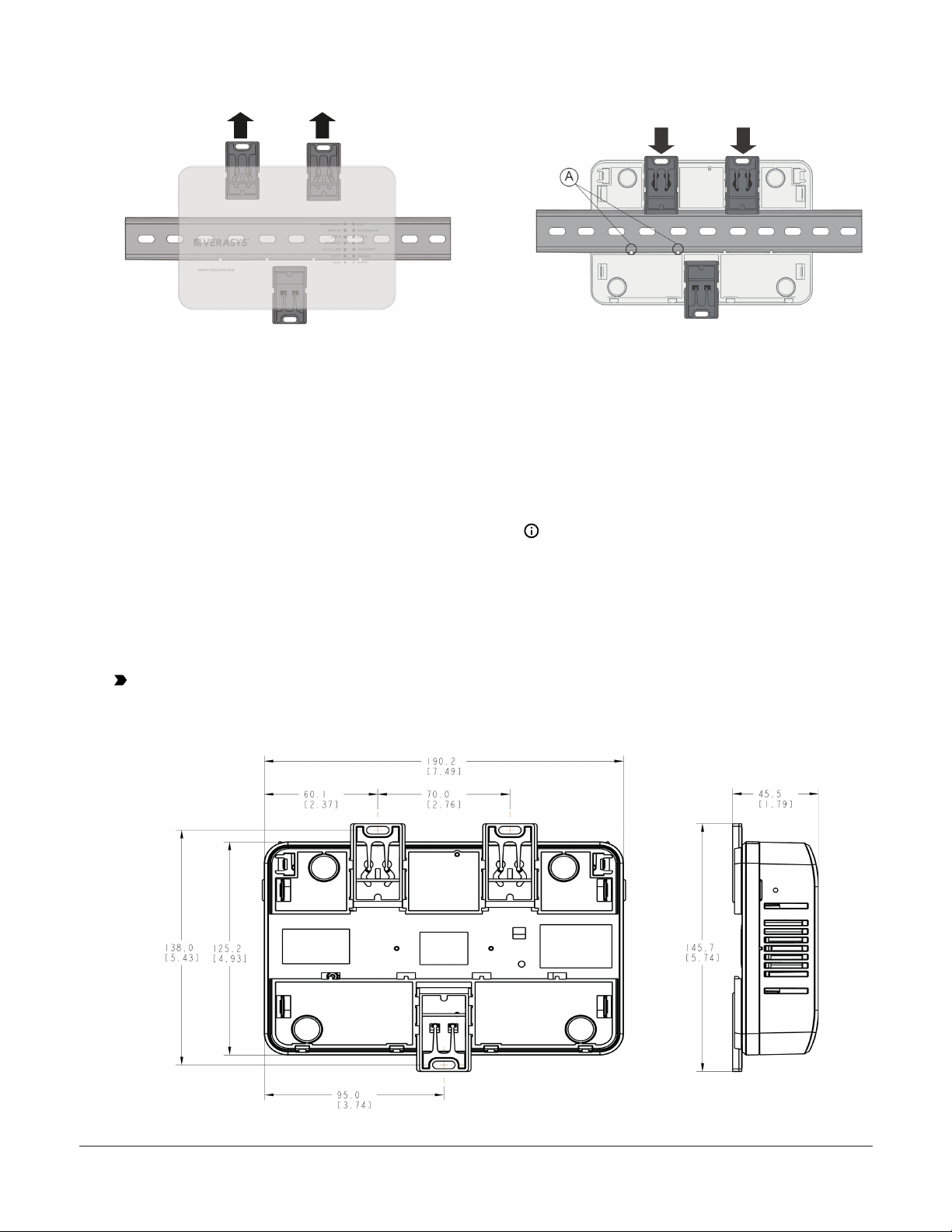
2. On the back of the SBH, extend the top two mounting
clips as shown in the following figure.
*241073700237C*
Part No. 24-10737-00237 Rev. C
2020-01-17
(barcode for factory use only)
LC-SBH200-0, LC-SBH200-0S, LC-
SBH200-0E, LC-SBH200-0LA

Figure 1: Top mounting clips extended (front view)
3. Place the SBH on the DIN rail as shown in the
following figure, so that the DIN rail channel hooks
(A) at the bottom of the baseplate channel catch the
lower part of the DIN rail.
4. Push the top mounting clips down to secure the SBH
on the DIN rail, as shown in the following figure.
Figure 2: Top mounting clips in downward position (rear
view)
5. To remove the SBH from the DIN rail, extend the top
mounting clips to the extended position and carefully
lift the SBH off the DIN rail.
Wall mounting
1. Pull the top two mounting clips upwards to their
extended position.
2. Mark mounting hole locations on the wall. Use the
dimensions shown in Figure 3, or hold the bracket
against the wall and mark the hole locations through
the mounting clips.
Note: The screw holes on the SBH can
accommodate M3.5 and #6 screws.
3. Drill holes in the wall based on the locations marked
in step 2.
4. Insert wall anchors for each hole if necessary.
5. Hold the bracket in place, insert the screws through
the mounting clips and into the screw holes, and then
carefully tighten all screws.
Important: Do not overtighten the mounting screws. Overtightening the screws can damage the mounting
clips or bracket.
Figure 3: Mounting holes, flat-mounting (left) and side-mounting (right)
Verasys Smart Building Hub (SBH) Installation Guide SBH2002

Wiring
Wiring guidelines
Follow these guidelines when you wire the SBH:
• Do not hang the SBH from a cable connection.
• Provide slack in the cable between the SBH and the
device you connect it to.
System bus port
The SBH has one RS-485 system bus port that connects
through a blue, 4-terminal, system bus adapter. You can
also temporarily connect the system bus to a device using
the 6-pin RJ12 cable. For data transmission and other
specifications, see the Technical specifications section.
System bus communications connections
To connect the SBH to the system bus for communication,
use the system bus adapter on the SBH.
Note:
• The SBH has a dedicated system bus address
of 117 by default. You can change the default
address in the BACnet Settings menu. Ensure
that the SBH has a unique address on the system
bus network. The system bus can accommodate
one SBH.
• Performance of the SBH varies based on the
amount of traffic it accommodates.
USB port
The SBH200 has two USB 2.0 host (type A) ports and one
USB 2.0 client (type micro) port. The USB host ports are
dedicated for optional IO expansion modules.
• Do not use the USB port as a charging port.
• Do not connect devices other than those specified in
Johnson Controls® technical documentation.
• Use the USB ports only when needed.
Table 1: USB port pin designations
Pin number
(both ends of
cable) Signal name
1+5 VDC
2Data -
3Data +
4No connection
5Ground
USB
Connect the Wi-Fi adapter that comes with the SBH into
either of the USB ports.
The SBH also supports the third-party USB Wi-Fi adapters
listed in the following table.
Table 2: Supported third-party USB Wi-Fi adapters for
SBH
Manufacturer Model Name
D-LINK® DWA-131 E
Table 2: Supported third-party USB Wi-Fi adapters for
SBH
Manufacturer Model Name
D-LINK DWA-171 A
D-LINK DWA-171 C
NETGEAR® A6100
TP-LINK® Archer
PREMIERTEK® PT-8811AU
Ethernet port
The Ethernet port on the SBH is an 8-pin RJ45 jack. The
maximum allowable cable length is 100 m (328 ft).
External power supply connections
CAUTION
Risk of Property Damage.
Do not apply power to the system before checking all
wiring connections. Short circuited or improperly con-
nected wires may result in permanent damage to the
equipment.
ATTENTION
Risque de dégâts matériels.
Ne pas mettre le système sous tension avant d'avoir
vérifié tous les raccords de câblage. Des fils for-
mant un court-circuit ou connectés de façon incor-
recte risquent d'endommager irrémédiablement
l'équipement.
WARNING
Risk of Electric Shock.
Disconnect or isolate all power supplies before mak-
ing electrical connections. More than one disconnec-
tion or isolation may be required to completely de-en-
ergize equipment. Contact with components carrying
hazardous voltage can cause electric shock and may
result in severe personal injury or death.
Verasys Smart Building Hub (SBH) Installation Guide SBH200 3

AVERTISSEMENT
Risque de décharge électrique.
Débrancher ou isoler toute alimentation avant de
réaliser un branchement électrique. Plusieurs iso-
lations et débranchements sont peut-être néces-
saires pour -couper entièrement l'alimentation de
l'équipement. Tout contact avec des composants con-
ducteurs de tensions dangereuses risque d'entraîner
une décharge électrique et de provoquer des
blessures graves, voire mortelles.
To connect the SBH using the supplied external power
source, complete the following steps:
Important: Power should only be applied and
removed by connecting and disconnecting the
power cord from the 100 VAC to 240 VAC outlet.
Applying or removing power by connecting or
disconnecting the 24 VDC/AC connector can damage
the unit.
1. Connect the DC plug of the 24 VDC, 50 W, Class II
power supply to the power supply port of the SBH.
Alternatively, you can connect a 24 VAC power supply
with a 75 VA, Class II transformer.
2. Connect the power supply to the supplied power
cord.
3. Connect the power cord to a 100 VAC to 240 VAC
outlet.
Operation
Accessing Smart Equipment using the
SBH
When the SBH is physically connected to an MS/TP
network, you can access Smart Equipment devices. The
SBH connects to the network through the system bus
and can access the devices on the trunk through this
connection.
To interact with a device on the network to see its
setpoints, alarms, and other parameters, use a web-
enabled device that is connected to the SBH Wi-Fi network
to select the device. To use the network, you must have
a web-enabled device that uses a supported internet
browser.
Connecting to the SBH Wi-Fi network
1. The SBH permanently connects to the Verasys
system using the four-terminal system bus port. Wire
the system bus communications to the blue, four-
terminal connector and connect to the port as shown
in the following figure.
2. If the SBH is at the end of a line, set the end-of-line
(EOL) switch to ON.
Figure 4: Connecting the SBH to your equipment
3. Connect the Wi-Fi adapter to either of the USB ports.
4. Connect the RJ45 Ethernet port to the building
Ethernet network. Use instructions from the building
IT department.
5. In the Wi-Fi settings of your device or laptop,
connect to the SBH Wi-Fi network using the default
credentials. You can find the default credentials on
a sticker on the Smart Building Hub Quick Start Guide
(Part No. 24-10737-00229) that came with the SBH.
You can also find the default credentials on a sticker
on the back of the SBH.
6. To open the SBH browser interface, direct your
browser to www.smartbuildinghub.com.
Note: The SBH ships with a private
www.smartbuildinghub.com SSL certificate
installed to ensure secure communication.
However, this certificate does not indicate that
it is trusted in a browser. If you want to install
your own certificate, refer to Adding a Private
Key and Certificate to Smart Building Hub in the
Smart Building Hub Network and IT Guidance
Technical Bulletin (LIT-12012324).
7. Read and accept the SBH license agreement.
8. The first time you log in to the SBH, the Change
Password and Passphrase page appears. You must
change the admin password and Wi-Fi passphrase.
Verasys Smart Building Hub (SBH) Installation Guide SBH2004

Important: After you change the Wi-Fi
passphrase or SSID, the web server restarts and
you must rejoin the SBH Wi-Fi network using
the new passphrase. On some mobile devices,
you must select and forget the original SBH Wi-
Fi network before you rejoin the network with
the new passphrase. For example, on a laptop
running a Microsoft® Windows® operating
system, you must select and forget the original
Wi-Fi network before you rejoin.
a. In the New Admin Password field, replace the
default password. Enter the new password in the
Verify New Admin Password field to confirm the
change.
b. In the New Wi-Fi Passphrase field, replace the
Wi-Fi passphrase and click Save.
9. To see and interact with a device on the network, use
the web-enabled device or laptop that is connected
to the SBH Wi-Fi network.
When you physically connect the SBH to the MS/TP
network, all the devices on the network that have unique
addresses appear in the device list and are available to
configure.
Reset button operation and
descriptions
If you lose your password or if you want to restore the
unit to factory defaults, the SBH has the following two
reset functions:
•Network Reset
•Reset to Factory Defaults
Use the instructions in the following sections according
to the type of reset you require. For both resets, the
following information applies:
• The reset button is located on the front of the device,
on the lower left, under the LEDs, see the following
figure and Figure 6. To reach the reset button, use
a small screwdriver or similar tool as shown in the
following figure.
• If the SBH is connected to the network when you press
the reset button, it disconnects from the network.
• If you press the reset button for more than nine
seconds, the reset operation cancels.
• If a fault condition already exists, the reset button does
not work.
Figure 5: Reset button
Network Reset
The Network Reset function resets Wi-Fi and Ethernet
settings. Use this function when you forget your Wi-Fi
connection information. To reset the Wi-Fi and Ethernet
settings, complete the following steps:
1. Press and hold the RESET button for two seconds.
The FAULT LED flickers slowly.
2. Release the RESET button within three seconds. The
FAULT LED continues to flicker slowly.
3. Within five seconds, press the RESET button again,
and then immediately release it to confirm that you
want to reset Wi-Fi and Ethernet settings. If you do
not press the reset button to confirm within five
seconds, the reset operation is canceled.
Result: The Wi-Fi SSID and passphrase and Ethernet are
set to factory defaults. The LEDs stop flickering for two
seconds, then the LEDs return to normal operation based
on the current state of the device.
See Table 3 for more information about LED designations
and flicker behavior.
Reset to Factory Defaults
The Reset to Factory Defaults function resets all device
settings including user profiles. The function also resets
your SSL certificate to the Johnson Controls self-signed
certificate that is included in the device.This function is for
administrators who want to clear all user profiles from a
device. The Reset to Factory Defaults function does not
change the version of the software. If you run a software
upgrade, the SBH retains the upgraded software version
and does not reset to the factory default version .
Verasys Smart Building Hub (SBH) Installation Guide SBH200 5

Important: To use an SBH that is reset to factory
defaults, you must use the default login credentials.
Find the default credentials on a sticker on the
Smart Building Hub Quick Start Guide (Part No.
24-10737-00229) that came with the SBH. Also find
the default credentials on a sticker on the back of
the SBH.
To reset to factory defaults, complete the following
steps:
1. Press and hold the RESET button for six seconds.
After two seconds, the FAULT LED flickers slowly.
After an additional four seconds of holding the
RESET button, the FAULT LED changes to a faster
flicker.
2. Release the RESET button within three seconds of
seeing a fast flicker. The FAULT LED continues to
flicker quickly.
3. Within five seconds, press the RESET button again,
and then immediately release it to confirm that you
want to reset to factory defaults. If you do not press
the RESET button to confirm within five seconds, the
reset operation is canceled.
Result: All device settings reset to factory defaults. The
LEDs stop flashing for two seconds, and then the LEDs
return to normal operation based on the current state of
the device.
See Table 3 for more information on LED designations and
flicker behavior.
Reboot button
The SBH has a REBOOT button beside the RESET button.
The SBH has a super capacitor that, when charged, keeps
the SBH powered up for 30 seconds. To force a reboot
immediately, press the REBOOT button.
Status indication LEDs
The SBH uses status LEDs to indicate functional states
according to the LED map shown in the following figure.
Table 3 provides SBH LED functional information.
Figure 6: LED map
Table 3: SBH LED designations and operation
LED name Color Normal LED operation LED operation for all conditions
POWER Blue or
purple
On steady Off: The device has no power.
On purple: Primary voltage supplies power.
On blue: Operating system (OS) is initialized and primary voltage supplies
power.
FAULT Red Off Off: No faults. Device is operating normally.
On steady: Missing hardware or software, operating system is not yet initialized,
or reset is in progress.
Slow flicker then fast flicker: Reset button is being pressed.
Medium flicker: 2 blinks per second= startup sequence
Fast flicker: 5 blinks per second = other fault
ETHERNET Blue Flicker with activity Off: Receiving data
On steady: Transmitting data
Flicker: Data transmission
100/1G LINK Blue On steady Off: No network connection
On steady: Network is connected
RUN Blue On steady Off: No power or waiting for processes to start
On steady: OS and all monitored processes have started and the device is ready
to use.
UPGRADE Blue On steady Off: No upgrade is in progress
On steady: Upgrade is in progress
USB A Blue On when a device is
connected
Off: No device is connected
On steady: A device is connected
USB B Blue On when a device is
connected
Off: No device is connected
On steady: A device is connected
Verasys Smart Building Hub (SBH) Installation Guide SBH2006

Table 3: SBH LED designations and operation
LED name Color Normal LED operation LED operation for all conditions
SYSTEM BUS Blue Flicker with activity Off: Not receiving data
On steady: Transmitting data
Flicker: Data transmission
Wi-Fi AP Yellow Flicker with activity Off: No Wi-Fi adapter is connected
On steady: A device is connected to the Wi-Fi network of the SBH
Flicker: Wi-Fi adapter is connected but no devices are connected
EOL Yellow On if the device is the end
of the line
Off if it is in the middle of
the bus
Off: EOL not switched on
On steady: EOL is switched on
Wi-Fi CLIENT Yellow n/a Not currently used
LED test sequence at startup
During startup, the SBH automatically initiates a self test
to verify correct operation. Immediately after you connect
the supply power, the following LED lighting sequence
occurs:
• The POWER LED starts on purple and then turns blue
and stays on.
• The FAULT LED flashes for approximately 30 seconds,
then turns off and the RUN LED turns solid when the
SBH is fully functional.
• The Wi-Fi LEDs remain off until you connect the Wi-
Fi dongle. When you connect the Wi-Fi dongle, the
corresponding USB LED turns on and the Wi-Fi AP LED
flickers, which indicates that the SBH is waiting for a
device.
Repair information
Replace the SBH if it fails to operate within its
specifications. The SBH is not a serviceable product;
however, it does support software updates to enable
feature enhancements. For a replacement SBH, software
updates, or accessories, contact your local Johnson
Controls representative.
Do not open the SBH housing. The SBH has no user-
serviceable parts inside.
The SBH requires no periodic field maintenance.
Troubleshooting
Table 4: Launch issues troubleshooting information
Problem Resolution
When you launch a web browser,
it does not direct you to the SBH
login page.
Reason
Device operation varies based on the device and Internet browser you use. For example, some
devices cache browser information and do not automatically redirect you to the SBH login page
when you launch the browser.
Solution
Direct your browser to www.smartbuildinghub.com
When you upgrade a controller or
HVAC device that an SBH connects
to, the SBH does not display active
or current data.
Solution
Disconnect the SBH from the field controller system bus, and then reconnect it.
When you install the SSL certificate
on your device, it asks you to re-
install it.
Solution
1. Verify that the time on your client device is correct. If the device time is not current, for
example, after a hard reset, close the browser, set the time, and then try to install the
certificate.
2. Check your web browser settings and verify that cookies are enabled.
Verasys Smart Building Hub (SBH) Installation Guide SBH200 7

Table 4: Launch issues troubleshooting information
Problem Resolution
When you install the SSL key or
certificate, the message Error
Saving SSL Settings appears.
Reason
When an SSL key or certificate is corrupted, the SSL page detects it and alerts you to the corrupted
key or certificate. However, if the corruption is minor, for example, if you copied an extra space
while installing the certificate, or you missed a character, the UI does not detect the problem and
saves the corrupted key or certificate. The server detects the error and returns the Error Saving SSL
Settings message. This correctly prevents the bad key or certificate from being used, but it does not
inform you about the source of the problem.
Solution
Reinstall the SSL key or certificate as described in the Smart Building Hub Network and IT Guidance
Technical Bulletin (LIT-12012324).
Accessories
Table 5: SBH200 Accessories
Code Number Description Shipped with
ACC-PWRKIT-1A24
AC-PWRKIT-1D24
Verasys LC-SBH200-0 power supply for North America
ACC-PWRKIT-1E24 Verasys LC-SBH200-0 power supply for Europe
LC-SBH200-0S
LC-SBH200-0E
ACC-WIFIKIT-0DU Verasys LC-SBH200-0 USB Wi-Fi adapter for North America and Europe LC-SBH200-0
LC-SBH200-0S
LC-SBH200-0E
Technical specifications
Table 6: Technical specifications SBH
Power consumption 38 W maximum
Ambient temperature
conditions
Operating: 0°C to 50°C (32°F to 122°F)
Operating survival: -30°C to 60°C (-22°F to 140°F)
Non-operating: -40°C to 70°C (-40°F to 158°F)
Ambient humidity
conditions
Storage: 5% to 95% RH 30°C (86°F) maximum dew point conditions
Operating: 10% to 90% RH, 30°C (86°F) maximum dew point conditions
Transmission speeds Serial communication (SA/FC bus): 9600, 19.2k, 67.8k, or 115.2k bps
Ethernet communication: 10 Mbps, 100 Mbps, 1 Gbps
Transmission range
(typical)
Wireless communication:
30 m (100 ft) line-of-sight indoors
91 m (300 ft) line-of-sight outdoors
Network and serial
interfaces
Two SA/FC ports (RJ12 6-pin port; connects with 1.5 m [4.9 ft] RJ12 field bus cable, and one screw terminal
plug, 4-pin)
Three USB ports (one Micro-B port, and two USB A ports). All support USB 2.0 and Open Host Controller
Interface [Open HCI] specification
Dimensions
(H x W x D)
190 mm x 125 mm x 44.5 mm (7.48 in. x 4.92 in. x 1.75 in.)
Housing White Polycarbonate and Acrylonitrile butadiene styrene (ABS) blend
Weight .387kg (.852 lbs)
Web browser
requirements for
computers and handheld
devices
Computer:
Windows Internet Explorer® 10 and Windows Internet Explorer 11, or Google® Chrome™
Handheld device:
The handheld device must run either Internet Explorer Mobile for Windows® Mobile version 5 or version
6 operating system (OS); Android™ or Google Chrome. Other web browsers may display the UI, but the
functionality is not guaranteed.
Verasys Smart Building Hub (SBH) Installation Guide SBH2008

Table 6: Technical specifications SBH
United States: UL Listed File E107041, CCN PAZX, UL 916, Energy Management Equipment, FCC Compliant
to CFR47, Part 15, Subpart B, Class A.
Compliance
Canada: UL listed file E107041, CCN PAZX7, CAN/CSA C22.2 No.205, Signal Equipment; Industry Canada
Compliant.
Europe: CE Mark - Johnson Controls declares that this product is in compliance with the essential
requirements and other relevant provisions of the EMC Directive.
Australia and New Zealand: RCM Mark, Australia/NZ Emissions Compliant.
The performance specifications are nominal and conform to acceptable industry standard. For application at conditions
beyond these specifications, consult the local Johnson Controls office. Johnson Controls shall not be liable for damages
resulting from misapplication or misuse of its products.
Product warranty
This product is covered by a limited warranty, details of which can be found at www.johnsoncontrols.com/
buildingswarranty.
Software terms
Use of the software that is in (or constitutes) this product, or access to the cloud, or hosted services applicable to
this product, if any, is subject to applicable terms set forth at www.johnsoncontrols.com/techterms. Your use of
this product constitutes an agreement to such terms.
Patents
Patents: http://jcipat.com
Single point of contact
APAC Europe NA/SA
JOHNSON CONTROLS
C/O CONTROLS PRODUCT MANAGEMENT
NO. 32 CHANGJIJANG RD NEW DISTRICT
WUXI JIANGSU PROVINCE 214028
CHINA
JOHNSON CONTROLS
WESTENDHOF 3
45143 ESSEN
GERMANY
JOHNSON CONTROLS
507 E MICHIGAN ST
MILWAUKEE WI 53202
USA
Building Technologies and Solutions
507 E Michigan Street, Milwaukee, WI 53202, USA
Verasys® and Johnson Controls® are registered trademarks of Johnson Controls
All other marks herein are the marks of their respective owners.
Contact information
Contact your local branch office: www.johnsoncontrols.com/locations
Contact Johnson Controls: www.johnsoncontrols.com/contact-us
Verasys Smart Building Hub (SBH) Installation Guide SBH200 9

© 2020 Johnson Controls. All rights reserved. All specifications and other information shown were current as of document revision and
are subject to change without notice.
www.johnsoncontrols.com
Other manuals for SBH200
2
Table of contents
Other Verasys Switch manuals