VERDER Carbolite Gero CDF 15/1b Guide

1 MF56 –1.05
Installation, Operation &
Maintenance Instructions
1530°C Chamber Furnaces
CDF 15/1b
This manual is for the guidance of operators of the above Carbolite Gero products
and should be read before the furnace is connected to the electricity supply.
CONTENTS
Section page
1.0 Symbols & Warnings 2
2.0 Installation 2
3.0 Operation 4
4.0 Maintenance 6
5.0 Repairs & Replacements 8
6.0 Fault Analysis 12
7.0 Circuit Diagrams 13
8.0 Fuses & Power Settings 14
9.0 Specifications 15

CDF
2 MF56 –1.05
1.0 SYMBOLS &WARNINGS
1.1 Switches and Lights
1.2 Warning Symbols
2.0 INSTALLATION
2.1 Unpacking & Handling
When unpacking or moving the furnace always lift it by its base. Never lift it by the door. Use two
or more people to carry the furnace where possible. Remove any packing material from the door
gear and furnace chamber before use.
NOTE: This product contains Refractory Ceramic Fibre (better described as Alumino Silicate
Wool) for precautions and advice in handling this material see the ‘Repairs and Replacements’
section.
2.2 Siting & Setting Up
Place the furnace in a well ventilated room, away from other sources of heat, and on a surface
which is resistant to accidental spillage of hot materials. Do not mount the furnace on an
inflammable surface.
DANGER of electrical shock–read any warning printed by this symbol.
DANGER –hot surface. Read any warning printed by this symbol.
WARNING: all surfaces of a furnace may be hot.
DANGER –read any warning printed by this symbol.
Heat Light: the adjacent light glows or flashes to indicate that power is
being supplied to the elements
Instrument switch: when the instrument switch is operated the temperature
control circuit is energised.
Caution: Double pole/neutral fusing.

CDF
MF56 –1.05 3
Ensure that there is free space around the furnace. Do not obstruct any of the vents in the control
section: they are needed to keep the controls cool.
Ensure that the furnace is placed in such a way that it can be quickly switched off or disconnected
from the electrical supply - see below.
If the chimney is supplied unfitted, then fit it into the hole in the top of the furnace case. If the
furnace is to be used to heat substances which emit fumes, then a fume extraction duct of about
150mm inlet diameter may be placed directly above the chimney outlet. Do not make a sealed
connection to the furnace chimney as this causes excessive airflow through the chamber and
results in poor temperature uniformity.
2.3 Hearth Tile
The cast hearth is packed separately and should be fitted into the recess in the bottom of the
chamber before the elements are fitted (See Photo)
2.4 Heating Elements
The Silicon Carbide elements are VERY FRAGILE and are packed separately. Fit them according to
the instructions in section 5.7.
2.5 Electrical Connections
Connection by a qualified electrician is recommended.
Check the furnace rating label before connection. The supply voltage should agree with the voltage
on the label, and the supply capacity should be sufficient for the amperage on the label.
The supply should be fused at the next size equal to or higher than the amperage on the label. A
table of the most common fuse ratings is also given in section 8.1 of this manual.
The furnace is supplied with a 16 amp IEC plug and should be connected using a suitably rated
mains cable.
Connection by line plug: the plug should be within reach of the operator, and should be quickly
removable.
Connection to isolating switch: this should operate on both conductors (single phase).
The supply MUST incorporate an earth (ground).
ELECTRICAL CONNECTION DETAILS
supply type
Supply
Terminal label
Cable colour
Live-Neutral
Reversible or Live-Live
1-phase
L
Brown
To live
to either power conductor
N
Blue
To neutral
to the other power conductor
PE
Green/Yellow
To earth (ground)
to earth (ground)

CDF
4 MF56 –1.05
Technical Notes
The furnaces covered by this manual have electronically controlled power limits. Do not attempt to
calculate the Amps from the Wattage. High break capacity fuses should be used. Avoid fast-blow
fuses and magnetic trip circuit breakers - consult Carbolite Gero if in doubt.
3.0 OPERATION
3.1 Operating Cycle
The furnace is fitted with an Instrument switch. The switch cuts off power to the control circuit.
Connect the furnace to the electrical supply.
Operate the instrument switch to activate the temperature controller. The controller becomes
illuminated and goes through a short test cycle.
Close the furnace door and adjust the temperature controller –see the controller manual.
To turn the Furnace off, set the Instrument switch to it’s off position; the controller display will go
blank. If the furnace is to be left off unattended, isolate it the electrical supply.
3.2 General Operating Advice
Heating element life is shortened by use at temperatures close to maximum. Do not leave the
furnace at high temperature when not required. The maximum temperature is shown on the
furnace rating label and on the back page of this manual.
When heating large objects, in particular poor conductors, avoid shielding the thermocouple from
the heating elements. The thermocouple is intended to sense the temperature near the heating
element, but if a large object is placed in the chamber it may record the average temperature of the
object and the elements, which can lead to overheating of the elements. Allow large objects to gain
heat at a lower temperature and then reset the controller to a temperature close to the desired
maximum.
When heating materials which produce smoke or fumes, the chimney must be correctly fitted and
unobstructed. Otherwise, soot can accumulate in the chamber and could possibly cause an
electrical breakdown of the heating element.
If the furnace is used to heat materials which emit smoke or fumes, regularly heat it up to
maximum temperature for one hour without load to burn away the soot.
Materials such as case hardening compounds and other reactive salts may penetrate the furnace
chamber lining and attack the insulation, or the elements, causing premature failure. Use of a
hearth tile may be advisable: please consult our technical department.
Light weight ceramic fibre insulation can easily be marked by accidental contact. Some fine cracks
may be visible on the surface of the insulation, or may develop in the surface of the chamber due
to the progressive shrinkage of the insulation materials. Cracks are not usually detrimental to the
functioning or the safety of the furnace.
3.3 Use of Probes
Any metal object used to probe into the furnace chamber while the furnace is
connected to the supply must be earthed (grounded). This applies in particular to
metal sheathed thermocouples, where the sheaths must be earthed. The refractory

CDF
MF56 –1.05 5
material of the chamber lining becomes partly conducting at high temperatures, and the electric
potential inside the chamber can be at any value between zero and the supply voltage. Unearthed
probes can cause serious electric shock.
3.4 Atmospheres
Chamber furnaces are not gas tight, so it should be understood that gas usage may be high, and that
the chamber is likely always to contain some air. Residual oxygen levels of 1% are to be expected.
In practice inert or oxidising gases may be used, but not combustible or toxic gases.
3.5 Operator Safety
The furnace incorporates a safety switch which interrupts the heating element circuit when the
door is opened. This prevents the user touching a live heating element, but also prevents the
furnace from heating up if the door is left open. The operation of this switch should be checked
periodically –see section 4.1.2.
Avoid burns: furnace surfaces can be hot. Before you remove a hot object from the furnace make
sure you have a safe place to put it down.

CDF
6 MF56 –1.05
4.0 MAINTENANCE
4.1 General Maintenance
Preventive rather than reactive maintenance is to be preferred. The type and frequency depends on
furnace use: the following are recommended.
4.1.1 Cleaning
Soot deposits may form inside the furnace, depending on the process. At appropriate intervals
remove these by heating as indicated in section 3.2.
The furnace outer surface may be cleaned with a damp cloth. Do not allow water to enter the
interior of the case or chamber. Do not clean with organic solvents.
4.1.2 Safety Switch
The door switch operation mentioned in 3.5 should be checked periodically to ensure that heating
elements are isolated when the door is opened. In normal conditions the safety arrangement should
outlast the furnace, but it could be affected by rough handling, a corrosive environment or work
materials, or exceptional frequency of use.
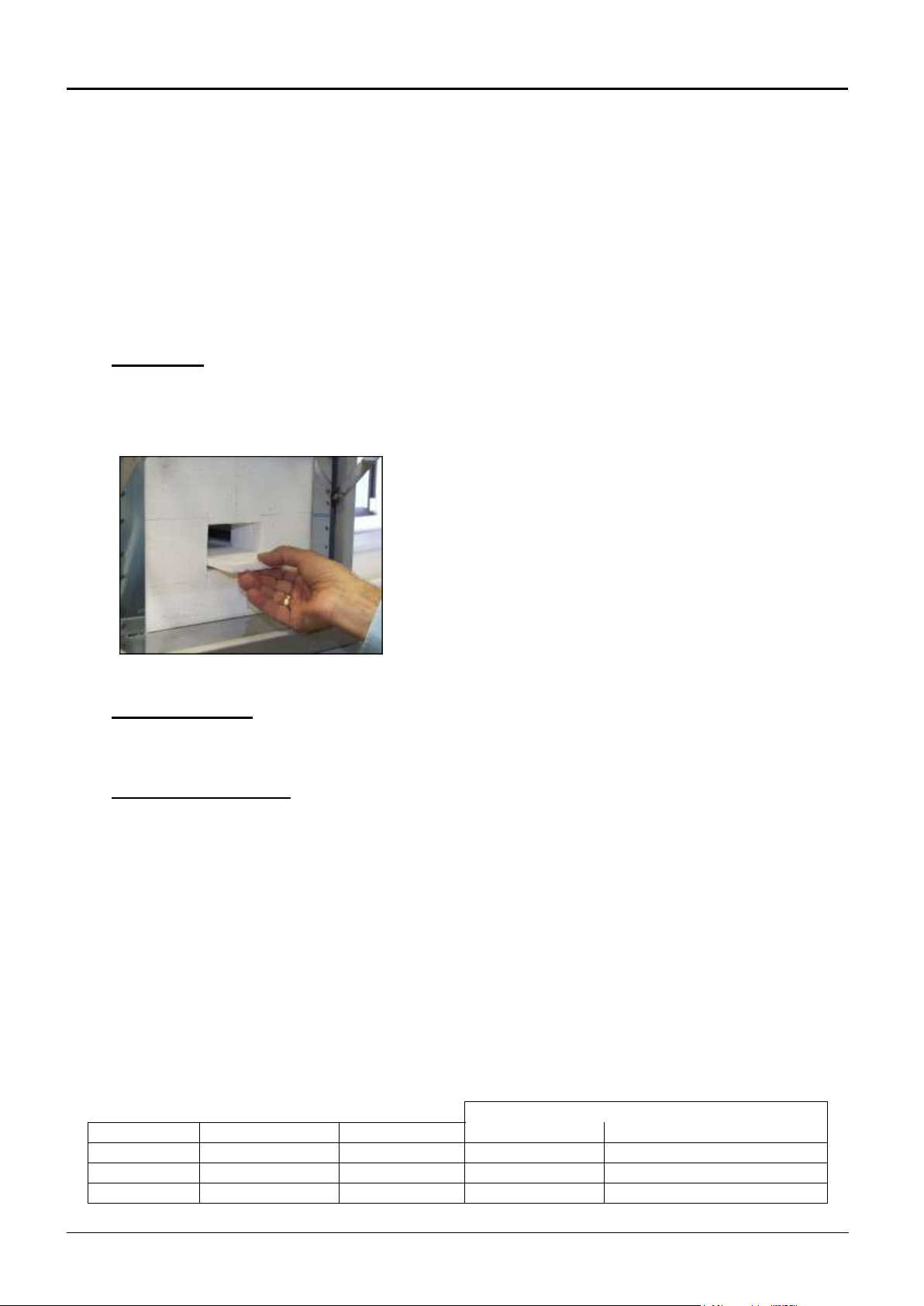
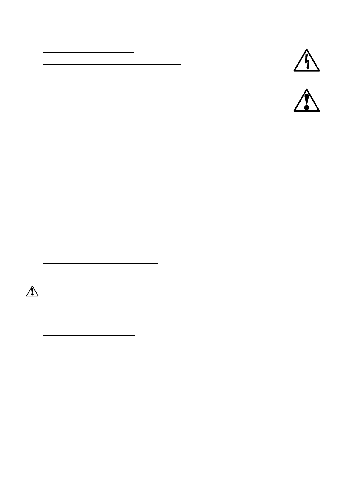
A qualified electrician should check that the supply to the heating elements is cut, with and
without power being on, when the door is open partially and fully; it is important that isolation is
not just marginally achieved. The check is best made on the element terminals after removal of the
furnace back: probing the element surface inside the furnace could be inconclusive because of
surface oxidation. Note that both live and neutral of a 1-phase supply, should be isolated when the
door is opened.
4.1.3 Element Ageing and Power Adjustment
See sections 4.5 and 4.6.
4.2 Calibration
After prolonged use the controller and/or thermocouple could require recalibration. This would be
important for processes which require accurate temperature readings or which use the furnace
close to its maximum temperature. A quick check using an independent thermocouple and
temperature indicator should be made from time to time to determine whether full calibration is
required. Carbolite Gero can supply these items.
Depending on the controller, the controller manual may contain calibration instructions.
4.3 After Sales Service
Carbolite Gero’s service division (Carbolite Gero Service) has a team of Service Engineers
capable of repair, calibration and preventive maintenance of furnace and oven products at our
customers’ premises throughout the world. We also sell spares by mail order. A telephone call or
fax often enables a fault to be diagnosed and the necessary spare part despatched.
Each furnace has its own record card at Carbolite Gero. In all correspondence please quote the
serial number, model type and voltage given on the rating label of the furnace. The serial number
and model type are also given on the front of this booklet when supplied with a furnace.
To contact Carbolite Gero Service or Carbolite Gero see the back page of this manual.
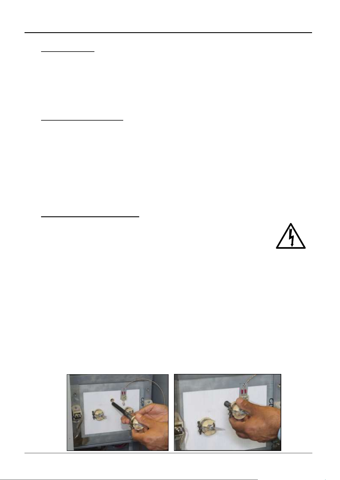
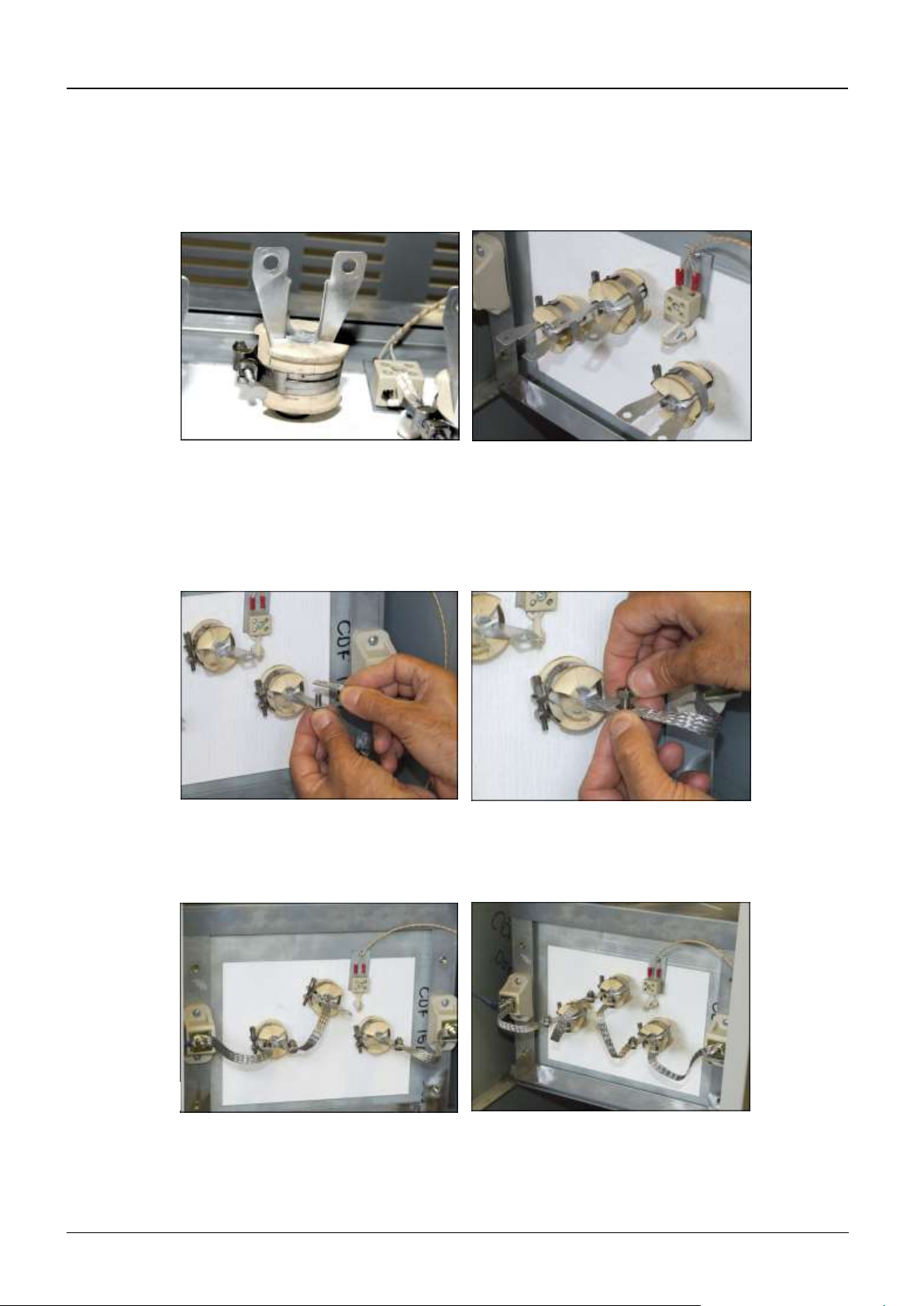
4.4 Recommended Spares Kits
Carbolite Gero can supply individual spares, or a kit of the items most likely to be required. This
can save time in the event of a breakdown. Each kit comprises one thermocouple, one sheath, one
solid state relay, one door insulation piece, a set of elements, and a set of braids. Individual spares
are also available.
When ordering spares please quote the model details as requested above.

CDF
MF56 –1.05 7
4.5 Element Ageing
Silicon carbide elements gradually increase in resistance with use: a process known as ageing.
Their heating power reduces correspondingly.
If the furnace does not reach temperature, or is slow, the elements have aged to a high a resistance
and it may be necessary to replace them.
4.6 Power Adjustment
The furnace control system incorporates electronic power limiting. Power is supplied to the
elements in bursts of about 1/3rd second duration. This prevents overheating of the elements. The
power limit is compensated for, by the aid of the soft start function which will limit the initial
output power until a programmed temperature is reached, whereby the furnace can control the
ramp rate of the program without applying full power.

CDF
8 MF56 –1.05
5.0 REPAIRS &REPLACEMENTS
5.1 Safety Warning –Disconnection from Supply
Always ensure that the furnace is disconnected from the supply before repair work is
carried out.
5.2 Safety Note - Refractory Fibrous Insulation
Insulation made from High Temperature Insulation Wool
Refractory Ceramic Fibre, (better described as Alumino Silicate Wool) (ASW)
This product contains alumino silicate wool products in its thermal insulation. These materials
may be in the form of blanket or felt, formed board or shapes, mineral wool slab or loose fill wool.
Whilst there is no evidence of any long term health hazards, we strongly recommend that safety
precautions are taken whenever the materials are handled.
Exposure to fibrous dust may cause respiratory disease.
When handling the material always use an approved respiratory protection equipment
(RPE-i.e. FFP3), eye protection, gloves and long sleeved clothing.
Avoid breaking up waste material. Dispose of waste in sealed containers.
After handling rinse exposed skin with water before washing gently with soap (not
detergent). Wash work clothing separately.
Before commencing any major repairs we recommend reference to the European Association
representing the High Temperature Insulation Wool industry (www.ecfia.eu)
We can provide further information on request. Alternatively our service division can quote for
any repairs to be carried out at your premises or ours.
5.3 Temperature Controller Replacement
301. These controllers are fitted to the back of the control panel, which can be separated from the
base by removal of two screws.
Before handling the controller: wear an anti-static wrist strap or otherwise avoid any possibility
of damage to the unit by static electricity.
Refer to the instructions supplied with the replacement controller.
5.4 Solid-state Relay Replacement
Disconnect the furnace from the supply and remove the furnace back panel.
Make a note how the wires are connected to the solid state relay, and disconnect them.
Remove the solid state relay from the base panel or aluminium plate.
Replace and reconnect the solid state relay ensuring that the heat-conducting thermal pad is
sandwiched between the relay and the base panel or aluminium plate. Alternatively a thin layer of
white, heat-conducting silicon paste may be applied between the new relay and the plate.
The new solid state relay contains a built-in MOV which protects it from short periods of excess
voltage.
Replace the removed panel.

CDF
MF56 –1.05 9
5.5 Fuse Replacement
Fuses are marked on the circuit diagram (section 7.0) with type codes, e.g. F1, F2. A list of the
correct fuses is given in section 8.1.
If any fuse has failed, it is advisable for an electrician to check the internal circuits.
Replace any failed fuses with the correct type. For safety reasons do not fit larger capacity fuses
without first consulting Carbolite Gero.
The fuses are near the cable entry point, and access is by removal of the back panel.
5.6 Thermocouple Replacement
Disconnect the furnace from the supply, and remove the furnace back panel.
Make a note of the thermocouple connections. The negative leg of the thermocouple is marked
blue. Compensating cable colour codings are:
negative: white
positive (type R): orange
Disconnect the thermocouple from its terminal block.
Bend the metal tag, or release the screw, to release the thermocouple sheath; withdraw the sheath,
and shake out any fragments of thermocouple.
Re-assemble with a new thermocouple observing the colour coding, ensuring that the
thermocouple is not twisted as it is being inserted and that sheath is refastened.
5.7 Element Fitting and Replacement
Replacements: read the section on element ageing (4.5).
Disconnect the furnace from the electrical supply and remove the furnace back panel
to gain access to the element connections.
Remember that the elements are fragile and expensive, and that they can be damaged by
contamination: handle them with care and keep them clean.
5.7.1 Fitting Elements
Ensure that there is no packaging or other objects within the chamber.
Fit Hearth tile: Read Section 2.3
Remove rear panel by unscrewing the 6 retaining screws and disconnecting the earth cable.
From the rear of the furnace, visually check the element location holes for any obstructions.
Carefully unpack the 3 elements.
Carefully take an element and align with element locations hole, in the rear of the brickbox
(See photo 1)
Photo 1
Photo 2

CDF
10 MF56 –1.05
Gently insert the element into the location hole until it reaches the approximate depth of the front
face insulation. (See photo 2) This should require no force at all. Then with a slight twisting action
locate the front end of the element in the front face location hole and gently insert element as far as
possible.(See photo’s 3 & 4) Again no force is required. There should be approximately 6-8 mm
between the elements porcelain terminal connector and the rear insulation.
Repeat the above procedure for the other two elements.
The braids should then be connected as follows. Starting from one side. Take the loose end of
braid that is connected to the connection block (See Photo 5) and attach to the first element tail of
the nearest element using M6 screw, washer, nut (See Photo 6).
Connect the second element tail of the same element to the first element tail of the centre element
using the same method with the loose braids provided (See Photo 7). Repeat this process on the
opposite side.
Once the braids are all connected and the fixings secured, carefully tidy the braids and ensure they
are not touching each other or any other component (See Photo 8).
Photo 3
Photo 4
Photo 5
Photo 6
Photo 7
Photo 8

CDF
MF56 –1.05 11
New furnace: the diagrams indicate the connections. If you have any problems with this procedure,
please contact our service division. A common feature of CDF models is that elements are in
series between 200-240 volts.
Replacements: make a note of the actual braid and cable connections to the elements. Using the
reverse method described above, disconnect the braids or cables and carefully withdraw each
element.
Carefully insert the new elements into the furnace and attach the braids according to the notes
made, or according to the appropriate diagram below
Whether fitting new elements or replacing old, replace the furnace back panel when connections
are complete remembering to connect the earth cable to the back.
Element connections –3 Elements
Photograph shows typical live and neutral connections
L1
N

CDF
12 MF56 –1.05
6.0 FAULT ANALYSIS
A.
Furnace Does Not Heat Up
1.
The HEAT light
is ON
The heating
element has failed
Check also that the SSR is working
correctly
2.
The HEAT light
is OFF
The controller
shows a very high
temperature or a
code such as 0000
The thermocouple has broken or has a
wiring fault
The controller
shows a low
temperature
The door switch(es) (if fitted) may be
faulty or need adjustment
The contactor (if fitted) may be faulty
The SSR could be failing to switch on due
to internal failure, faulty logic wiring from
the controller, or faulty controller
There are no lights
glowing on the
controller
Check the supply fuses and any fuses in the
furnace control compartment
The controller may be faulty or not
receiving a supply due to a faulty switch or
a wiring fault
B.
Furnace Overheats
1.
The HEAT light
goes OFF with
the instrument
switch
The controller
shows a very high
temperature
The controller is faulty
The controller
shows a low
temperature
The thermocouple may have been shorted
out or may have been moved out of the
heating chamber
The thermocouple may be mounted the
wrong way round
The controller may be faulty
2.
The HEAT light
does not go off
with the
instrument
switch
The SSR has failed
“ON”
Check for an accidental wiring fault which
could have overloaded the SSR

CDF
MF56 –1.05 13
7.0 CIRCUIT DIAGRAMS
In all CDF models the safety switch in the diagram is a positive-break door switch.
EMC Filters (if fitted): dependent on the model there may be one filter, or more than one fitted in
parallel. The circuit diagram example does not show multiple filter arrangements.
7.1 Single Phase
SSR
TC
Control thermocouple
G
P
Coil
R
Instrument Switch
Safety
Switch
F2
F2
if fitted
Filter
F1
Heat
F1
N
L
GR/Y
PE
BU
R
BU
Contactor
L
Element(s)

CDF
14 MF56 –1.05
8.0 FUSES &POWER SETTINGS
8.1 Fuses
F1-F3: Refer to the circuit diagrams.
F1
Internal
supply fuses
Fitted if supply cable fitted.
Fitted on-board to some types of EMC filter.
16 Amps:
38mm x 10mm type F
F2
Auxiliary
circuit fuses
Fitted on-board to some types of EMC filter.
May be omitted up to 10 Amp/phase supply rating.
2 Amps glass type F
On board: 32mm x 6mm
Customer
fuses
Recommended if cable fitted.
See rating label for
amperage; see table below
for fuse rating.
Model
phases
Volts
Supply Fuse Rating
CDF 15/1b
1-phase
200-230
13A/ph

15 MF56 –1.05
9.0 SPECIFICATIONS
Carbolite Gero reserves the right to change specifications without notice.
9.1 Models Covered by this Manual
MODEL
Max.
Temp.
Max.
Power
Chamber Size (mm)
Approx.
Capacity
Net
Weight
(°C)
(kW)
H
W
D
(l)
(kg)
Chamber Furnaces heated by Silicon Carbide elements.
CDF 15/1b
1530°C
2.0
80
90
150
1.1
40
9.2 Environment
The furnaces contain electrical parts and should be stored and used in indoor conditions as
follows:
temperature:
5°C - 40°C
relative humidity:
maximum 80% up to 31°C decreasing linearly to 50% at 40°C

Carbolite Gero Limited, Parsons Lane, Hope,
Hope Valley, S33 6RB, England.
Telephone: +44 (0)1433 620011
Fax: +44 (0)1433 621198
E-mail: info@carbolite-gero.com
The products covered in this manual are only a small part of the wide range of ovens, chamber
furnaces and tube furnaces manufactured by Carbolite Gero for laboratory and industrial use. For
further details of our standard or custom built products please contact us at the address below, or
ask your nearest stockist.
Copyright © 2016 Carbolite Gero Limited
For preventive maintenance, repair and calibration of
all Furnace and Oven products, please contact:
Carbolite Gero Service
Telephone: +44 (0)1433 624242
Fax: +44 (0)1433 624243
Email: ServiceUK@carbolite-gero.com
MF56 –1.05 01/01/16
Table of contents
Popular Dental Equipment manuals by other brands

W&H
W&H Assistina MB-302 Instructions for use

mectron
mectron MICROPIEZO Use and maintenance manual

Schick
Schick QUBE II Original instruction

Waterpik
Waterpik Waterflosser WP-950 Series quick start guide

FKG
FKG Rooter X3000 user manual

Dentsply Sirona
Dentsply Sirona Cavitron Select SPS Instructions for use