Veris Industries H8126-CB User manual

-1-
Installation Instructions
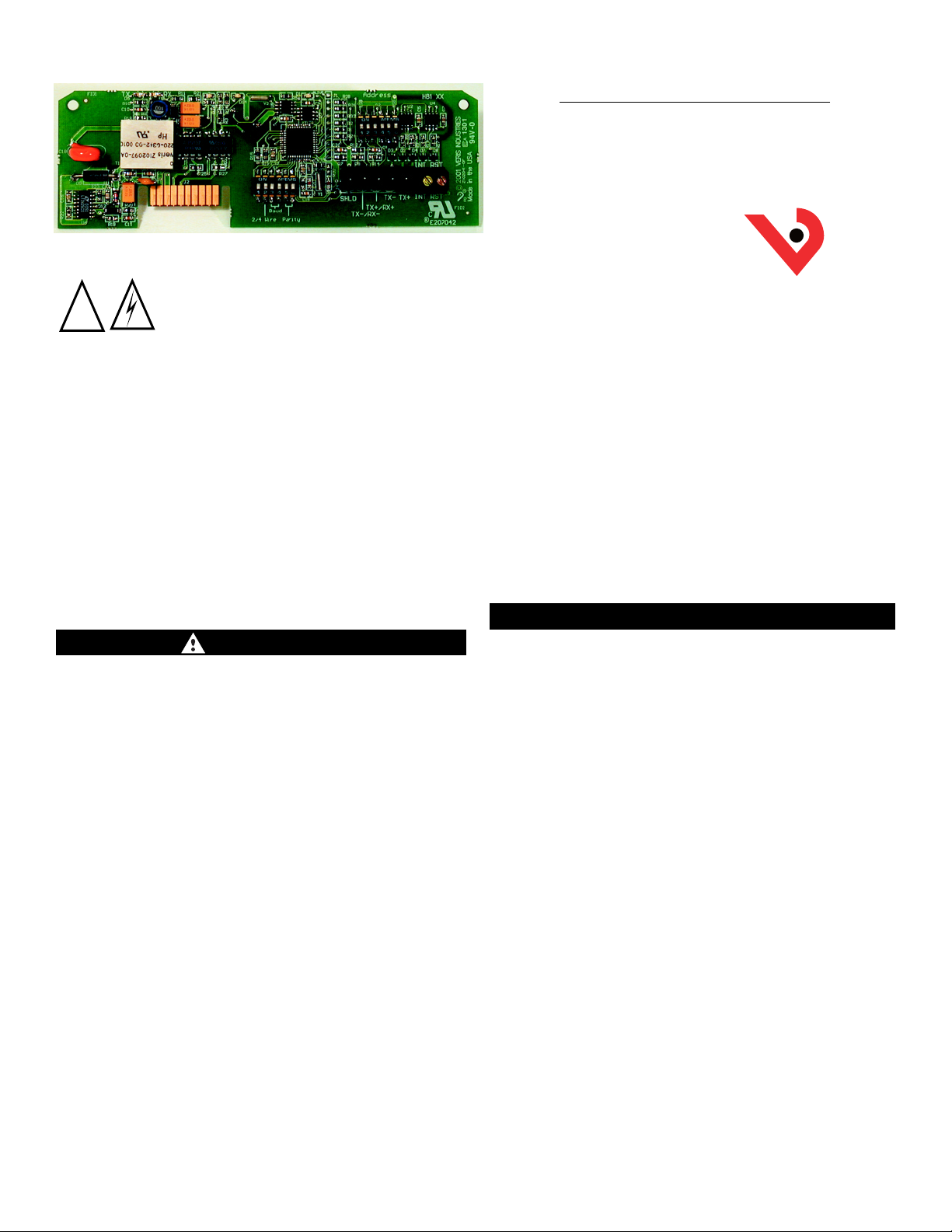
H8126-CB
Energy Meter
Communication Board, N2
DESCRIPTION
The H8126-CB Energy Meter Communication Board is an optional
field-installable board for the H8163 Energy Meter, providing N2
communications capability. The H8126-CB also enables the Energy
Meter to provide true kW & kVAR Demand information.
The easy-to-install H8126-CB provides a simple, cost-effective way to
network the Energy Meter on the N2 bus.
Applications
■Commercial tenant submetering
■Performance contracting
■Cost allocation
■Real time power monitoring via local display or through control/data
acquisition systems.
Features
■Easily network to existing systems via N2 RS-485 output
■Metasys compatible
• This product is not intended for life or safety applications.
• This product is not intended for installation in
hazardous or classified locations.
• Read instructions thoroughly before installing
this equipment.
Severe injury or death can result from electrical shock
during contact with high voltage conductors or related
equipment. Disconnect and lock-out all power sources
during installation and service. Applications shown
are suggested means of installing sensors, but it is the
responsibility of the installer to ensure that the
installation is in compliance with all national and
local codes. Installation should be attempted only by
individuals familiar with codes, standards, and proper
safety procedures for high-voltage installations.
!
VERIS INDUSTRIES
PORTLAND, OREGON USA
Toll Free in USA 1.800.354.8556
®
Tel USA 1.503.598.4564
FAX USA 1.503.598.4664
http://www.veris.com
email: [email protected]
P/N Z103167-0A
HAZARD OF ELECTRIC SHOCK, BURN OR EXPLOSION
• Only qualified workers should install this equipment. Such work
should be performed only after reading this entire set of instructions.
•NEVER work alone.
• Before performing visual inspections, tests, or maintenance on this
equipment, disconnect all sources of electric power. Assume that
all circuits are live until they have been completely de-energized,
tested, and tagged. Pay particular attention to the design of the
power system. Consider all sources of power, including the
possiblity of backfeeding.
• Turn off all power supplying the energy meter and the equipment
in which it is installed before installing the H8126-CB.
NOTE: The energy meter may be connected to multiple power
sources.
CAUTION: ESD-SENSITIVE COMPONENTS
Use an anti-static or grounding strap (customer-supplied) to
ground yourself and discharge any static charge before installing
the EMCB. Static can damage electrostatic discharge-sensitive
components in the circuit monitor and its accessories. Avoid
touching the gold plated connector points.
Failure to follow this instruction can result in equipment damage.
• Beware of potential hazards, wear personal protective equipment,
and carefully inspect the work area for tools and objects that may
have been left inside the equipment.
• The successful operation of this equipment depends upon proper
handling, installation, and operation. Neglecting fundamental
installation requirements may lead to personal injury as well as
damage to electrical equipment or other property.
Failure to observe these instructions will result in death or
serious injury.
DANGER!

-2-
1. RS-485 LED (TX)-D5
Red LED; blinks to indicate that the H8126-CB is
transmitting data to the master.
2. RS-485 LED (RX)-D6
Red LED; blinks to indicate that the H8126-CB is
receiving data from the master.
3. LED from Main Board (RX)-D13
Green LED; blinks to indicate that the H8126-CB is
receiving data from the main board.
4. LED from Main Board (TX)-D14
Green LED; blinks to indicate that the H8126-CB is
transmitting data to the main board.
5. “ALIVE” LED-D1
Green LED; should blink once per second to
indicate normal operation of the H8126-CB.
6. N2 Network Address DIP Switches
Use these DIP switches to set the network address
for the H8126-CB. See pg. 3 for settings.
7. Connection to Energy Meter
Install the H8126-CB in the energy meter by inserting
this connector into the connection slot at the top
of the energy meter.
8. Communication DIP Switches
N2 factory default.
COMPONENT LOCATIONS
9. RS-485 Communication Terminals
Insert the RS-485 connector into these terminals.
See Figure 6 on page 4 for instructions on wiring
the connector for 2-wire communications.
10. End of Demand Subinterval Terminal
Use this terminal as the input connector for “end
of demand interval” signal from the utility or
other source. See Figure 1a.
Figure 1
ON
123456
ON
123456
12
TX RX
3
RX
4
TX
5
6
7
8
910
ALIVE
LITHIUM BATTERY
D5 D6D13 D14D1
N2+
N2-
REF
10
COM N.O.
Figure 1a
CAUTION! Danger of Explosion if battery is
incorrectly replaced. Replace only with the
same or equivalent type recommended by
the manufacturer.
Dispose of used
batteries according
to the
manufacturer’s
instructions.
!
An interposing isolated relay should be used as the
dry contact for this terminal. No voltage should be
applied to this connection.

-3-
This section describes the communications settings you must
make to the H8126-CB. When daisy-chaining N2 devices,
follow these guidelines:
• You can connect up to 63 H8126-CB devices on a single
daisy chain.
• Each H8126-CB device on the daisy chain must have a
unique address. Before connecting the H8126-CB to the
RS-485 communication wires, set the address according to
directions in “Selecting the Network Address DIP Switches”
on this page. If you assign the same address to two
devices, neither device will communicate.
• For RS485 cables, use shielded, twisted-pair wire
(Belden Cable 1120A or equivalent).
• Terminate the last device on the daisy chain. If the H8126-CB
is the last device, see instructions in under “RS-485
Communications”.
Selecting The Network Address – DIP Switches
Use the Network Address DIP switches to select the network
address. Each H8126-CB on a daisy chain must have a unique
network address (from 1–63). Devices with the same address
will be unable to communicate.
Always set the address before you install the H8126-CB in the
energy meter and before you connect the energy meter to the
daisy chain.
Each of the six DIP switches has a unique address value, page 7
lists DIP switch positions for specific addresses.
Network Address DIP Switch Values
Switch Value
11
22
34
48
516
632
INSTALLATION
communications connection and terminating the H8126-CB
(if it is the last device in its daisy chain).
Wiring the Connector
For this procedure, use the 5 pin connector from the RS-485
communication terminals of the H8126-CB (see page 4). To
wire RS-485 communications, follow these steps:
1. Wire the communications connector as shown in Figure 6
2. Use a small, flat-blade screwdriver to tighten the
connector screws.
3. Plug the 5 pin connector into the RS-485 communication
terminals of the H8126-CB.
4. If the H8126-CB is the last device on the daisy chain,
terminate it, following directions in “Terminating the
H8126-CB” on page 5.
Figure 2
8 + 32 = 40
In this example, the network address
for the device is 40. From Figure 2,
you can see that switch 4 and 6 offer
the only combination of values that
total 40.
This figure illustrates how to set the
switches. Up is ON; down is OFF.
Figure 3
RS-485 COMMUNICATIONS
Selecting Wiring Type, Baud Rate, and Parity– Communication
DIP Switches
Factory set to N2 specifications
This section describes the procedures for wiring the

-4-
RS-485 COMMUNICATIONS
ON
123456
ON
123456
TX RXRX TX ALIVE
D5 D6D13 D14D1
N2+
N2-
REF
TX+
REF N2+
N2-TX–
SHIELD
TX+
REF TX–
MASTER SLAVE
N2+
N2-
2-wire Communications Wiring
Detail showing N2 connector
wired for 2-wire communication.
*See note on page 5 regarding
terminating the H8126-CB.
Figure 6

-5-
RS-485 COMMUNICATIONS
Terminating the H8126-CB
If the H8126-CB is the last device in a daisy chain, you need to
terminate it to ensure reliable communication per the RS-485
standard (120 ohm nominal impedence). See Figure 7.
This section provides information on installing the H8126-CB in
the energy meter.
Before you begin this procedure, ensure that all addressing
and configuration DIP switches are set correctly.
INSTALLING THE H8126-CB
DANGER
HAZARD OF ELECTRIC SHOCK, BURN, OR EXPLOSION!
• Remove the voltage terminal and all fuses from the
energy meter.
• Use a properly rated voltage sensing device to confirm
that all power is off.
Failure to follow these instructions may result in death
or serious injury.
CAUTION
ESD-SENSITIVE COMPONENTS
Use an anti-static or grounding strap (customer-supplied)
to ground yourself and discharge any static charge
before installing the EMCB. Static can damage electro-
static discharge-sensitive components in the circuit
monitor and its accessories.
Failure to follow this instruction can result in equipment
damage.
The H8126-CB is designed as a plug-and-play accessory for the
H8163 energy meter. Follow these instructions to install the
H8126-CB into the energy meter.
1. Turn off all power to the energy meter and the equipment
in which it is installed. To turn off power to the energy
meter, do this:
a. Remove the voltage terminal from the energy meter
and all fuses.
b. Always use a properly rated voltage sensing device to
confirm that power is off.
2. To discharge static, follow the instructions that come with
your anti-static or grounding strap.
NOTE: We recommend using an anti-static or grounding
strap until you have completed installation of the H8126-CB.
3. Insert the communication terminal onto the RS-485
communication terminals.
4. Slide the H8126-CB into the slot in the energy meter. The
sides of the H8126-CB slide down into the channels on
either side of the energy meter. When the male connection
to the energy meter (see Figure 8) clicks into place, the
H8126-CB is properly installed.
5. If the external demand subinterval feature is used,
connect the wires into the end of the demand subinterval
terminal, which is called out on page 2, #10.
6. Replace the voltage terminal into the energy meter.
SLOTS
TOP
COMMSBOARD
BATTERY
CONNECTORS
CONNECTION
SLOTS
Figure 8 H8126-CB Installation
TX+
REF N2+
N2-TX–
Figure 7

-6-
TROUBLESHOOTING
This section covers the solutions for some of the common problems you might encounter with the H8126-CB.
There are five LEDs that indicate various types of communication. Figure 9 indicates the locations of these LEDs.
All LEDs will blink when operating normally.
If there is a problem communicating, first be sure that the board is properly seated in its slots on the energy meter. Verify that
the connector has clicked into place in the connection slot of the energy meter.
ON
123456
12
TX RX
3
RX
4
TX
5
6
ALIVE
D5D6D13D14D1
Figure 9 LED Positions on the H8126-CB
Number LED Abnormal Operation Solution
1 RS-485 LED (TX)-D5 Not Blinking There is no communication from the H8163 to the master.
Check the wiring; N2- and N2+ may be reversed. Correct the
wiring. Check Figure 6, pg. 4 for wiring diagram.
If RX LED-D6 is blinking, verify the DIP switch
address, parity, baud rate, and wire type.
2 RS-485 LED (RX)-D6 Not Blinking There is no communication from the master. Check the N2- and
N2+ wires as they may be reversed. Check Figure 6, pg. 4,
for wiring diagram.
3 From main board LED Not blinking The main board is not responding. Contact the factory for
(RX)-D13 support.
4 From main board LED Not blinking but There is an internal communications board error. Contact
(TX)-D14 “Alive” LED (D1) the factory for support.
is blinking
5 “Alive” status-D1 Steadily lit There is an internal communications board error. Contact
the factory for support.

-7-
N2 DIP SWITCH SETTINGS
The figure below illustrates the switch settings, using the Network Address DIP switches, for each Network address. See
“Selecting the network Address– NETWORK ADDRESS DIP SWITCHES” on page 3 for instructions on setting the switches.
DO NOT
USE ZERO!
32
33 34 35 36 37 38 39 40 41 42 43
44 45 46 47 48 49 50 51 52 53 54
55 56 57 58 59 60 61 62 63

-8-
NPT NPA OR WR Units Range Description
AI 1 Y Y kWH 0-33554432 Consumption
AI 2 Y Y kW 0-100.6 Power
AI 3 Y Y kVAR 0-100.6 Reactive Power
AI 4 Y Y kVA 0-100.6 Apparent Power
AI 5 Y Y 0-1.0 Total Power Factor
AI 6 Y Y Volts 5-528 Average Voltage, L-L
AI 7 Y Y Volts 3-305 Average Voltage, L-N
AI 8 Y Y Amps 1-110 Average Current
AI 9 Y Y kW 0-33.5 Real Power, phase A
AI 10 Y Y kW 0-33.5 Real Power, phase B
AI 11 Y Y kW 0-33.5 Real Power, phase C
AI 12 Y Y 0-1.0 Power Factor, phase A
AI 13 Y Y 0-1.0 Power Factor, phase B
AI 14 Y Y 0-1.0 Power Factor, phase C
AI 15 Y Y Volts 5-528 Voltage, phase A-B
AI 16 Y Y Volts 5-528 Voltage, phase B-C
AI 17 Y Y Volts 5-528 Voltage, phase A-C
AI 18 Y Y Volts 3-305 Voltage, phase A-N
AI 19 Y Y Volts 3-305 Voltage, phase B-N
AI 20 Y Y Volts 3-305 Voltage, phase C-N
AI 21 Y Y Amps 1-110 Current, phase A
AI 22 Y Y Amps 1-110 Current, phase B
AI 23 Y Y Amps 1-110 Current, phase C
AI 24 Y Y kW Demand 0-100.6 Present Demand Sub-Interval
This is the currently accumulating Sub-Interval demand,
which is constantly changing.
AI 25 Y Y kW Demand 0-100.6 Present Demand (kW)
This is the present demand, which is updated at the
end of every Sub-Interval. This value is the average
of the previous N sub intervals, where N is the
number of sub intervals (ADI 17).
AI 26 Y Y kW Demand 0-100.6 Peak Demand
The peak demand is the highest demand value (AI 25)
that has occurred. This is a Non-Volatile
point.*Note: This value is also Displayed on LCD for
MAX kW when the comms board is present.
AI 27 Y Y kVAR Demand 0-100.6 Present KVAR Sub-Interval
This is the currently accumulating Sub-Interval KVAR,
which is constantly changing.
AI 28 Y Y kVAR Demand 0-100.6 Present KVAR
This is the present KVAR, which is updated at the end of
every Sub-Interval. This value is the average of the
previous N sub intervals, where N is the number of sub
intervals (ADI 17).
AI 29 Y Y kVAR Demand 0-3072 Peak KVAR
The peak KVAR is the highest KVAR value (ADI 28)
that has occurred. This is a Non-Volatile point.
BI 1 Y N kWH 100A:0.0078125/count BI-1 is intended to be used as an accumulator
200A:0.015625/count (ACM) type. It should not be read as a binary
800A:0.0625/count status.
1600A:0.125/count
300A:0.03125/count
400A:0.03125/count
2400A:0.25/count
N2 OBJECTS

-9-
NPT NPA OR WR Units Range Description
ADI 1 Y N kWH 0-65535 LSW of kWH accumulator. Lower 16 bits of kWH.
ADI 2 Y N kWH 0-65535 MSW of kWH accumulator. Upper 16 bits of kWH
ADI 3 Y N 0-65535 Phase Loss, Latching Register (bit mapped):
bit 0: phase A (unpredictable results on phase A)
bit 1: phase B
bit 2: phase C
ADI 4 Y N 0-65535 Date/Time Month 1-12(LSB) Day 1-31(MSB)
ADI 5 Y N 0-65535 Date/Time Year 0-199(LSB) Hour 0-23(MSB)
ADI 6 Y N 0-65535 Date/Time Minutes 0-59(LSB) Seconds 0-59(MSB)
ADI 7 Y N Secs 0-65535 High Alarm Delay - sets the minimum time signal
must remain in state before the Alarm is set.
Default is 30 Sec.
ADI 8 Y N Secs 0-65535 High Warning Delay - sets the minimum time signal
must remain in state before the Warning is set.
Default is 30 Sec.
ADI 9 Y N Secs 0-65535 Low Warning Delay - sets the minimum time signal
must remain in state before the Warning is set.
Default is 30 Sec.
ADI 10 Y N Secs 0-65535 Low Alarm Delay - sets the minimum time signal
must remain in state before the Alarm is set.
Default is 30 Sec.
ADI 11 Y N 0-65535 Count of KWH resets
The number of times the KWH accumulator has been
reset. This value can never be reset. It will roll-over
from 65535 to zero.
ADI 12 Y N 0-65535 Count of Peak Demand Resets
The number of times the peak demand (ADI 26)
has been reset. This value can never be reset. It will
roll-over from 65535 to zero.
ADI 13 Y N 0-65535 Count of Peak KVAR Resets
The number of times the peak KVAR (ADI 29) has
been reset. This value can never be reset. It will roll-
over from 65535 to zero.
ADI 14 Y N 0-65535 Count of elapsed Sub Intervals
This counts the number of sub-intervals that have
elapsed. Because the demand (AI 25) is updated
every sub-interval, this register may be
read to determine if an identical value in (AI 25)
is actually the same demand interval or if it is a new
interval and the load has remained steady.
ADI 15 Y N 0-65535 Number readings in present sub-interval
This value indicates the number of readings that are
represented by the present sub-interval (AI 24 & AI 27).
This register acts as an unsigned integer. See below
for explanation of sub-interval reading count
overflow. This register will increment every 200 ms
(5 times per Second).
ADI 16 Y N 0-65535 Sub Interval Length
Sets the length of a sub-interval. Value is the
number of seconds * 5, eg 4500 is 15 minutes. For
sync-to-comms, or sync-to-demand-reset-input
(hardware signal), set this to zero.
Default is 4500.
ADI 17 Y N 1-6 Number of Sub Intervals per Demand Interval
Sets the number of sub-intervals that make a single
demand interval. Legal values are 1 to 6. For block
demand, set this to 1.
Default is 6.
N2 OBJECTS

-10-
NPT NPA OR WR Units Range Description
ADI 18 Y N 100-2400 CT Size
This register reads as the CT size, 100, 300, etc.
ADI 19 Y N 1-3 CT Number. The number of CT’s that are connected,
1,2,or 3.
ADI 20 Y N 0-65535 Count of Phase Losses
The number of times a phase loss has occurred on
any phase. This is can never be reset and will roll-
over from 65535 to zero.
ADI 21 Y N 0-65535 Phase Loss Timestamp, Month 1-12(LSB) Day 1-31(MSB)
ADI 22 Y N 0-65535 Phase Loss Timestamp, Year 0-199(LSB) Hour 0-23(MSB)
ADI 23 Y N 0-65535
Phase Loss Timestamp, Minutes 0-59(LSB) Seconds 0-59(MSB)
ADI 24 Y N 0-65535 Last Restart Timestamp, Month 1-12(LSB) Day 1-31(MSB)
ADI 25 Y N 0-65535 Last Restart Timestamp,Year 0-199(LSB) Hour 0-23(MSB)
ADI 26 Y N 0-65535 Last Restart Timestamp, Minutes 0-59(LSB)
Seconds 0-59(MSB)
ADI 27 Y N 0-65535 Last KWH Reset Timestamp, Month 1-12(LSB)
Day 1-31(MSB)
ADI 28 Y N 0-65535 Last KWH Reset Timestamp, Year 0-199(LSB)
Hour 0-23(MSB)
ADI 29 Y N 0-65535 Last KWH Reset Timestamp, Minutes 0-59(LSB)
Seconds 0-59(MSB)
ADI 30 Y N 0-65535 Firmware Version
ADI 31 Y N 0-65535 Firmware Revision
ADI 32 Y N 0-65535 Serial Number LSW
ADI 33 Y N 0-65535 Serial Number MSW
N2 OBJECTS

-11-
NPT NPA OR WR Units Range
BO 1 Y N 0=NA,1=Reset kHW accumulator
BO 2 Y N 0=NA,1=Reset Peak Demand
BO 3 Y N 0=NA,1=Reset Peak KVAR
BO 4 Y N 0=NA,1=Begin new demand sub-interval
BO 5 Y N 0=NA,1=Reset Phase Loss Register
LEGEND
OR: Object can be overridden
WR: Object can be written
RANGE: The AI ranges are based on a 3 phase 480V system with 100A CT’s.
NPT: Network Point Type
NPT: Network Point Address
UNITS: Engineering Units
DESCRIPTION: Point Description
Supported N2 Commands
0/0 - Time Update Message
0/4 - Poll without acknowledge message
0/5 - Poll with acknowledge message
1/1 - Read AI Command
1/6 - Read ADI command
1/2 - Read BI command
1/4 - Read BO command
2/1 - Write AI command
2/2 - Write BI command
2/4 - Write BO command
7/2/01 - Override AI command
7/2/06 - Override ADI command
7/2/04 - Override BO command
7/3/01 - Override Release AI request
7/3/06 - Override Release ADI request
7/3/02 - Override Release BI request
7/3/04 - Override Release BO request
F - Identify device type command
Demand Computation, Internal Algorithm:
The meter will compute average kw/kvar, by accumulating every kw/kvar reading and keeping a count of the number of kw/kvar
readings accumulated. This will occur every 200 ms (5 Hz). The accumulated value, divided by the number of kw/kvar readings,
will be the present sub-interval demand (kw/kvar), which may be read at registers AI-25 (KW) and AI-28 (KVAR).
A sub-interval may be terminated in three ways. A write to BO 4 will cause the present sub-interval to end. Second, if the
Hardware signal (interval reset) is detected. Last, the present sub interval will also end automatically if the sub interval length
(register ADI-16) has been set to a non-zero value. If the count of the number of kw readings equals or exceeds the non-zero
sub interval length, then the sub interval will be ended. While there are three ways to end a sub interval, it is expected that
applications will use only one of them.
The maximum legal sub-interval length is 65535 readings, which corresponds to 3 hours, 38 minutes, 27.2 seconds. When the
65536th reading is taken, the sub-interval reading counter will overflow. This condition is detected and causes the sub-interval
to end. The next sub-interval will begin on the next reading. In normal operation, it is expected that a sub interval should not
last longer than 1 hour.
When a sub-interval ends, the average kw/kvar during that sub-interval (which is the accumulated kw/kvar readings divided by
the number of readings) is added to a 6 value fifo that stores the 6 most recent sub-intervals. The kw/kvar accumulator and
count of kw/kvar readings are cleared to zero, to begin a new sub interval. The count of sub intervals (register ADI-14) is
incremented. The present demand is recomputed by averaging the first N elements of the fifo, where N is the value in register
ADI-17. If the new present demand is higher than the stored peak demand, then the peak demand is updated to the new
present demand.
N2 OBJECTS
Table of contents