Vernier VE User manual

User Manual for VE GSM Modem
INTRODUCTION
GSM/GPRS Smart Modem is a multi-functional, ready to use, rugged unit that can be embedded or plugged into any
application. The Smart Modem can be controlled and customized to various levels by using the standard AT commands.
The modem is fully type-approved, it can speed up the operational time with full range of Voice, Data, Fax and Short
Messages (Point to Point and Cell Broadcast), and the modem also supports GPRS (Class 10) for spontaneous data
transfer.
*The Smart Modem supports previous VEsions of Class 2 and the latest VEsions of Class 10.
The TCP/IP suite & PPP protocol is built in.
Physical Characteristics
Dimensions
93 x 81 x 26 mm ( excluding connectors)
Weight
125 grams
Housing
Metallic Enclosure
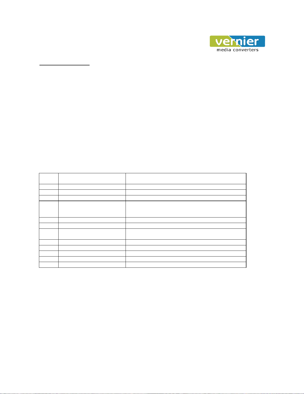
Functions –GSM Modes
Standard
Quad Band Extended GSM 850 / 900 MHz Class 4 (2W) and GSM 1800 / 1900 Class(1W)
Interface
Serial interface RS232/ RS485 V. 24/V.28 Auto bauding function
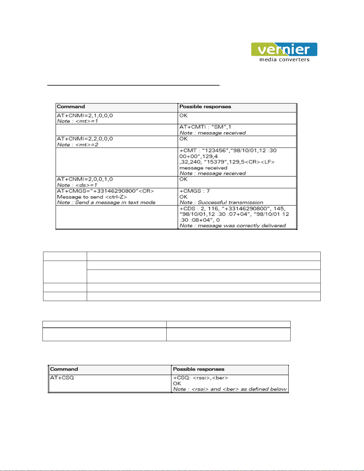
AT command set based on V.25ter and GSN 07.05 & 07.07
SMS
Mobile Originated (MO) and Mobile Terminated (MT),
Mode Text & PDU point to point. Cell broadcast. In accordance with GSM 07.05.
Data
Asynchronous 2400, 4800, 9600, 14400 upto 115000 bits/s
Transparent and Non Transparent mode
Audio
Half Rate/Full Rate/ Enhanced Full Rate.
Installing the Modem
To install the modem, plug the device on the provided SMPS Adapter.
Inserting/ Removing the SIM Card
To insert or Remove the SIM Card, it is necessary to press the SIM holder ejector button with Sharp edged object like a
pen or a needle. When this is done the SIM holder comes out a little, then pull it out and insert or remove the SIM Card.
Place the SIM Card Properly as per the direction of the installation. It is VEy important that the SIM is placed in the right
direction for its proper working condition.
Connecting External Antenna
Connect GSM/GPRS Smart Modem to the external SMA antenna male end. The Frequency of the
antenna should
be set
to
GSM850/900/1800/1900.
The right Antenna should be used with the specified frequency or else the Antenna can
damage the modem or it can affect the communication.
Power Supply –Screw type connector with 9-30V DC, 2A supply.
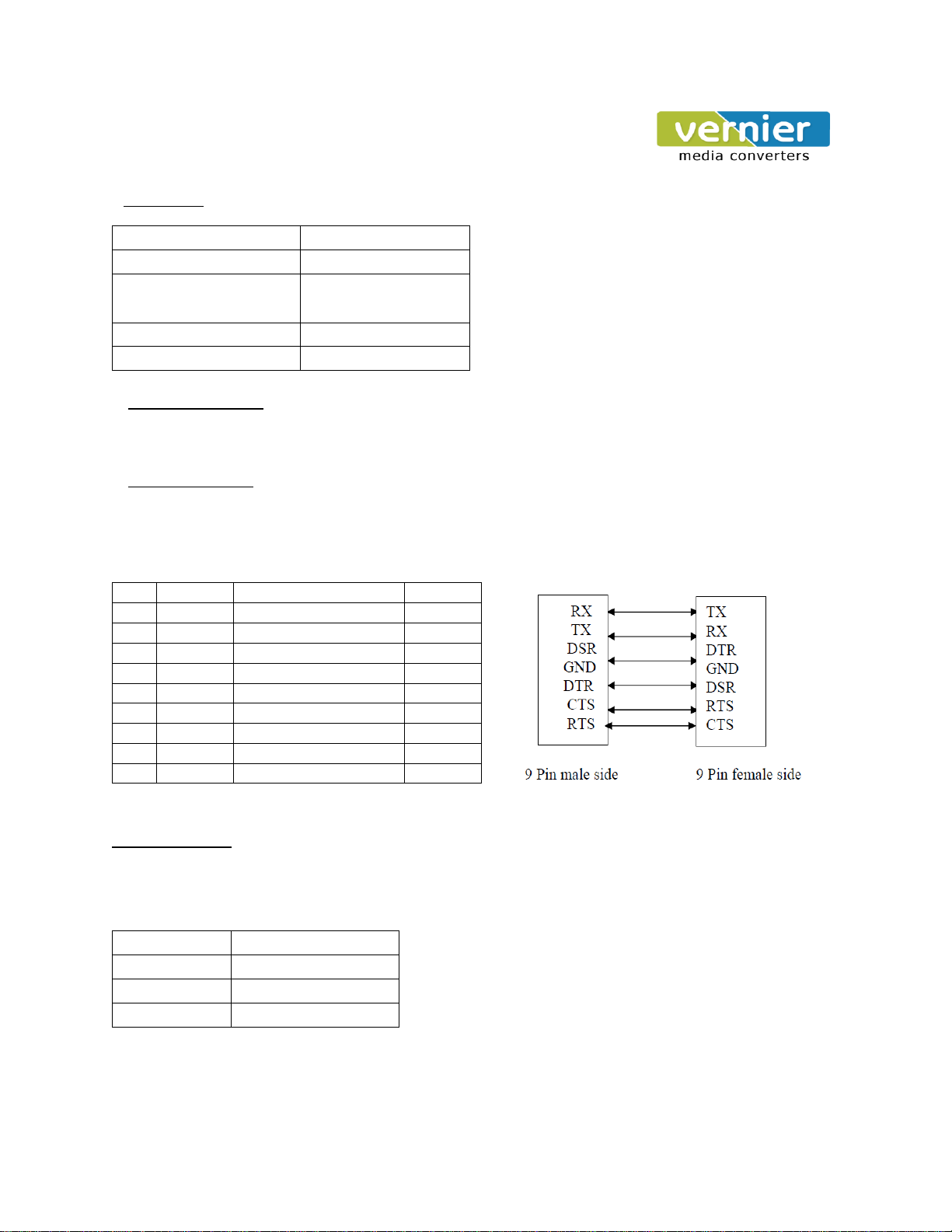
Connection Modem to external devices:
RS232/RS485 can be used to connect to the external device through the D-SUB/screw type connector device that is
provided in the modem

Connectors
Connector
Function
SMA
RF Antenna connector
9 pin D-SUB /3 pin screw
type
RS232 link / RS485 link
Adaptor Socket
Power Supply Connector
SIM Card holder
SIM Card
LED Status Indicator
Single LED to indicate Data / Registration / GPRS connectivityand Power ON.
RS232 Cable details
9 –PIN D-SUB Female Connector 9- PIN Serial Male to Female Cable Details
PIN
NAME
Designation
Type
1
NC
-
-
2
Tx
Transmit Data
Input
3
Rx
Receive Data
Output
4
DSR
Data Set Ready
Output
5
GND
Ground
Ground
6
DTR
Data Terminal Ready
Input
7
CTS
Clear to send
Output
8
RTS
Request to send
Input
9
NC
-
-
RS485 Cable details
RS485 is 2 wire interface which has following signals.
3 pin screw type connector
PIN
NAME
1
D+
2
D-
3
GND

Some basic AT Commands (for Dialing, SMS Read/write, signal quality)
SMS send/receive: Following commands selects the procedure for message reception from the network and
transmission to the network.
Dialing / Attending the Incoming call: Following commands selects the procedure for Dialing or initiating the call
and Attending the incoming call.
Commands
Possible Responses
ATDT
1234567890;
Ok, No carrier
Note: for dialing any fixed line, mobile no, No carrier is possible when signal quality is low, absence
of mobile signals.
ATA
Attending an incoming call.
ATH
Hung up the call
Modem connection with network: Following Commands indicates modem is entering into network.
Commands
Possible Responses
AT+CREG?
0,1-OK
0,2-Resnchronizingis attempt with network
Signal Quality +CSQ: This command is used to ascertain the received signal strength indication with or without a SIM
card inserted.
Note: All at commands are given at serial side with help of hyper terminal.

TROUBLESHOOTING:
Q. The modem does not answer through the serial link
A) Is the modem correctly powered on?
If not, the Check power Adapter, rating is INPUT –230 VAC, OUTPUT- 9-30V DC, 2AMPS
B) Is the serial cable suitable and adjusted in the modem and PC sockets?
A suitable cable must follow pin assignment described in PIN DETAILS
Check in particular, that Rx and Tx are properly connected for 3 wire communication
C) Check that your communicationprogram is properly configured:
Modem factory setting for the character framing are:
Data Bits: 8, Parity: None, Stop Bits: 1
The factory setting for the baud rate is 9600 bps.
D) Does any other program interfere with your communication program (conflict on communication port
access)?
If yes, close any application likely to interfere (e.g. mouse or printer driVE).
Q) The modem always returns «Error» when trying to issue a communication
A) Issue AT+CMEE=1 to have extended error code and retry
Error
Code
Diagnostic
Hint
0
Phone Failure
Call your technical support
3
Operations not allowed
4
Operation not supported
10
SIM not inserted
Insert the SIM card in the SIM holder of the Modem
If SIM card is inserted, insure that it is clean and properly
inserted
11
SIM PIN required
Enter PIN Code
12
SIM PUK required
Enter PUK code ( Call your network provider)
13
SIM Failure
Check validity of your SIM Card. If SIM damaged, call
network provider
16
Incorrect password
Check the code you entered
17
SIM PIN2 required
Enter PIN2
18
SIM PUK2 Required
ENTER PUK2 ( Call your Network Provider)
26
Dail String too long
Check your phone number ( max 20 digits)
30
No Network Service
For all other codes, and/or details, see AT commands manual.

PC with
Serial Com
Por
t
GSM
Modem
Basic Test Procedure for Data Transfer between Two GSM Modems:-
1)
Setup Diagram –
Serial Cable
GSM Ne
t
work
PC with
Serial Com
Por
t
GSM
Modem
Procedure- Serial Cable
1) Open HyperTerminalutility on PC1 with following serial setting –
¾ Baud rate –9600
¾ Data Bit –8
¾ Parity - None
¾ Stop bit - 1
¾ Flow control –None
Above serial parameter can be change as per setup
requirement.
2) Open Hyper terminal Utility on PC2 with setting given as above.
3) Connect both the modems to serial com ports.
4) Put the “Data Mode” activated SIM card in SIM card holder.
5) Power on the both modems, wait till the time ‘LED’on the modem starts Blinking.
6) Use following at commands for active the Data call for data transfer from hyper terminal.
¾ For Data call –ATD98XXXXXXXX–Modem will generate data call form PC1.
¾ For Auto answering- ATS0=2 - Issue this command on PC2 so the modem will answer the
call after two rings.
¾ Passing some time delay (less than 1min.) “Connect 9600”message will appear on both hyper
terminals it indicates data call has started.
7) Now type the data on hyper terminal of PC1; it should be appearing on another hyper terminal of PC2.
8) You can transfer file size between two hyper terminals using GSM modems.
P.O Box: 234911, Dubai, UAE
Tel : +971-4-2955966
Fax : +971-4-2955977
E-mail : sales@VEniertech.net
Table of contents
Popular Modem manuals by other brands

iDirect
iDirect X1 Series Installation, Support, and Maintenance Guide

Linksys
Linksys BEFCMU10 - Cable Modem With USB user guide

Digi
Digi Connect WAN 3G IA quick start guide

AOR
AOR ARD9900 instruction manual

Nivetec
Nivetec UNICOMM SAT-504 manual

Paradyne
Paradyne COMSPHERE 3821PLUS installation instructions