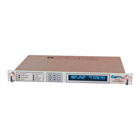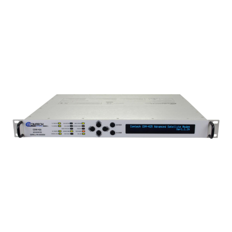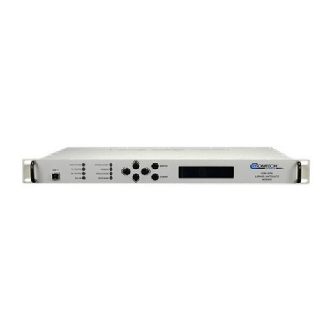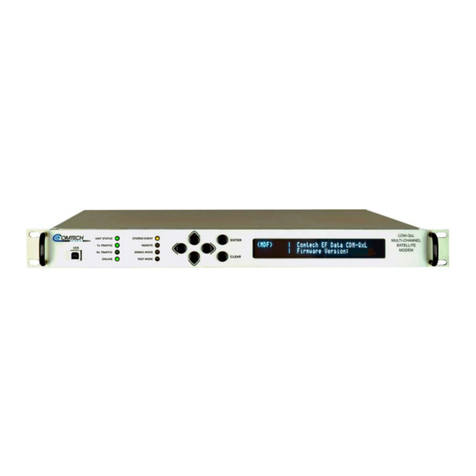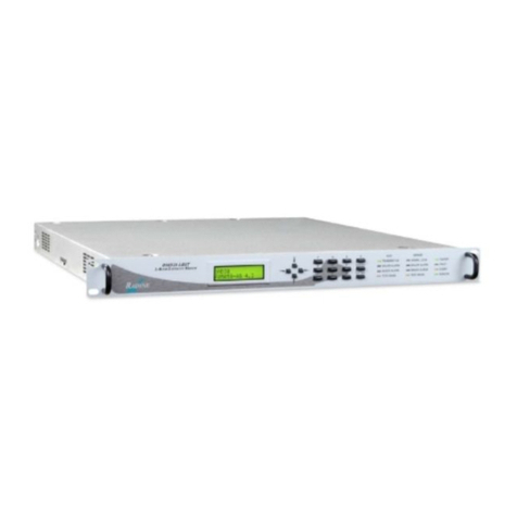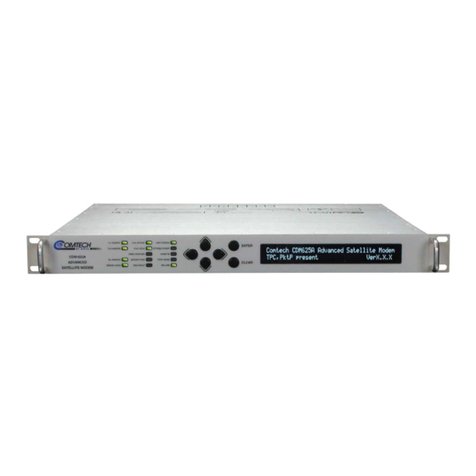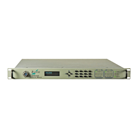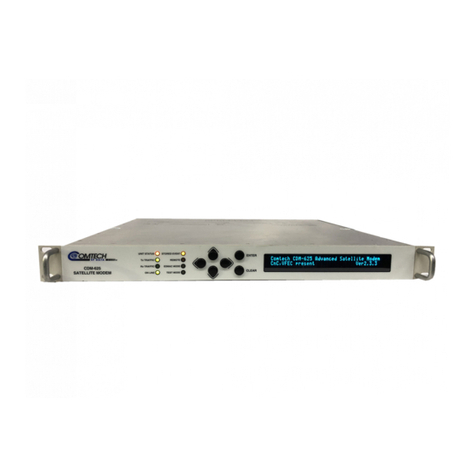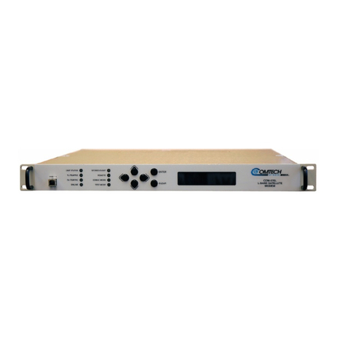
CDM-710/L Broadcast Satellite Modem MN/CDM710.IOM / CD-MNCDM710
Table of Contents Revision 12
v
2.1.7.3 Chassis Power Consumption...................................................................2–3
2.1.7.4 Chassis Fusing .........................................................................................2–3
2.1.7.5 IF Connectors ..........................................................................................2–3
2.1.7.6 Ethernet Connector.................................................................................2–4
2.1.7.7 Serial Connectors ....................................................................................2–4
2.1.7.8 Utility Connector.....................................................................................2–4
2.2 Operational Specifications...........................................................................2–5
2.2.1 Unit Configuration .......................................................................................... 2–5
2.2.2 Symbol Rates .................................................................................................. 2–5
2.2.3 Data Rate ........................................................................................................ 2–5
2.2.4 Symbol Rate/Data Rate .................................................................................. 2–5
2.2.5 Forward Error Correction (FEC) Types............................................................ 2–5
2.2.6 Operating Modes............................................................................................ 2–6
2.2.7 Transport Streams .......................................................................................... 2–6
2.2.8 Physical Layer (PL) Scrambling........................................................................ 2–6
2.2.9 Pilot Insertion ................................................................................................. 2–6
2.2.10 1:1 Redundancy .............................................................................................. 2–6
2.2.11 1:N Redundancy.............................................................................................. 2–6
2.2.12 Fault Handling................................................................................................. 2–6
2.2.13 External Tx Carrier Off .................................................................................... 2–7
2.2.14 Frequency Reference (Selectable).................................................................. 2–7
2.2.15 Test Functions................................................................................................. 2–7
2.2.16 Monitor Functions .......................................................................................... 2–7
2.2.17 Remote M&C Operations ............................................................................... 2–8
2.2.18 Spectral Mask ................................................................................................. 2–8
2.2.19 Firmware Update............................................................................................ 2–9
2.2.20 Modulator (Transmit) Specifications............................................................ 2–10
2.2.20.1 Frequency Range...............................................................................2–10
2.2.20.2 Impedance ........................................................................................ 2–10
2.2.20.3 ‘J1 | Tx’ Connector Type ................................................................... 2–10
2.2.20.4 Return Loss........................................................................................2–10
2.2.20.5 Output Power....................................................................................2–10
2.2.20.6 Output Power Accuracy ....................................................................2–10
2.2.20.7 Output Power Stability......................................................................2–11
2.2.20.8 Carrier Mute...................................................................................... 2–11
2.2.20.9 Carrier Null ........................................................................................2–11
2.2.20.10 Harmonics and Spurious ...................................................................2–11
2.2.20.11 Integrated Phase Noise.....................................................................2–11
2.2.20.12 Spectral Inversion .............................................................................2–11
2.2.20.13 Quadrature Phase Error .................................................................... 2–11
2.2.20.14 Quadrature Amplitude Imbalance ....................................................2–11
2.2.20.15 Combined Amplitude Imbalance and Quadrature Phase Error........ 2–12
