VERTICALLY URBAN SPECTRA DRIVE User manual

SPECTRA DRIVE
INSTALLATION INSTRUCTIONS
PLEASE ENSURE YOU HAVE READ THE FOLLOWING INSTRUCTIONS THOROUGHLY AND CAN
UNDERTAKE THE REQUIRED ACTIONS BEFORE COMMENCING INSTALLATION.
IF YOU HAVE ANY QUERIES, PLEASE CONSULT OUR TECHNICAL SUPPORT DEPARTMENT BEFORE
PROCEEDING.
012986

On-Site Manual
Page 2of 12
Page 2of 12
Contents
Scope.......................................................................................................................................................2
Revision History ......................................................................................................................................2
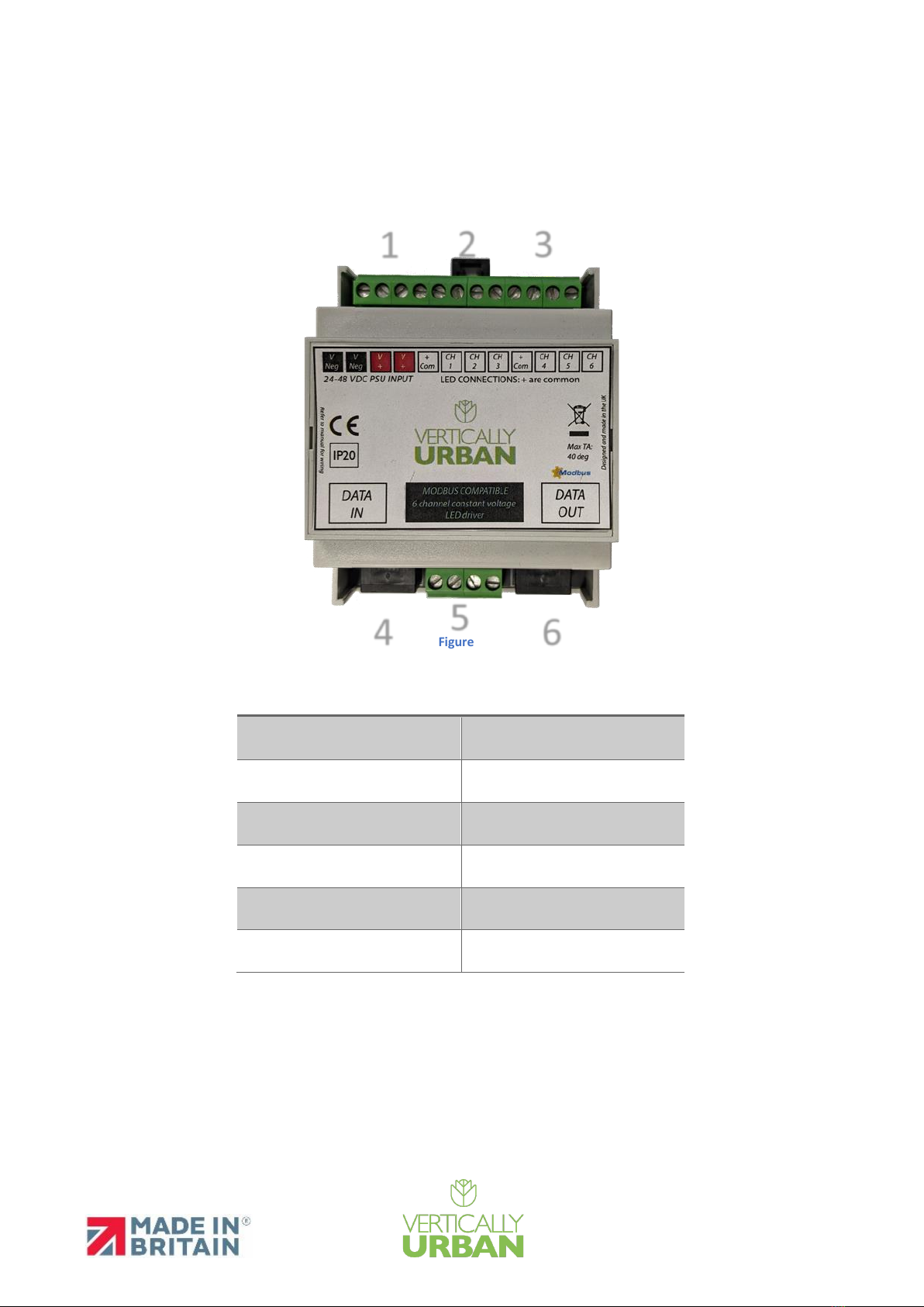
Overview.................................................................................................................................................3
Installation Instructions: .........................................................................................................................5
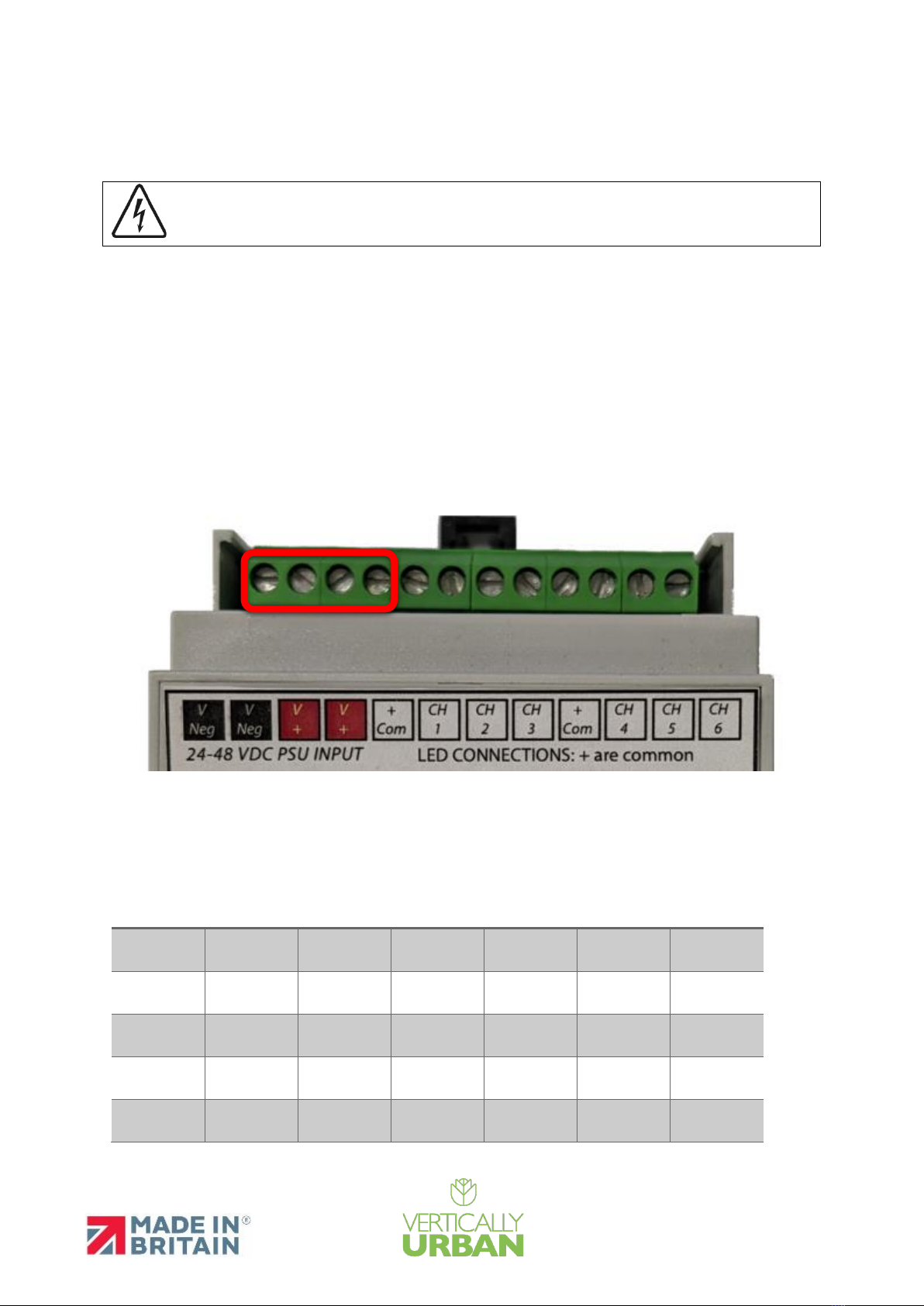
Powering the VU SPECTRA DRIVE.......................................................................................................5
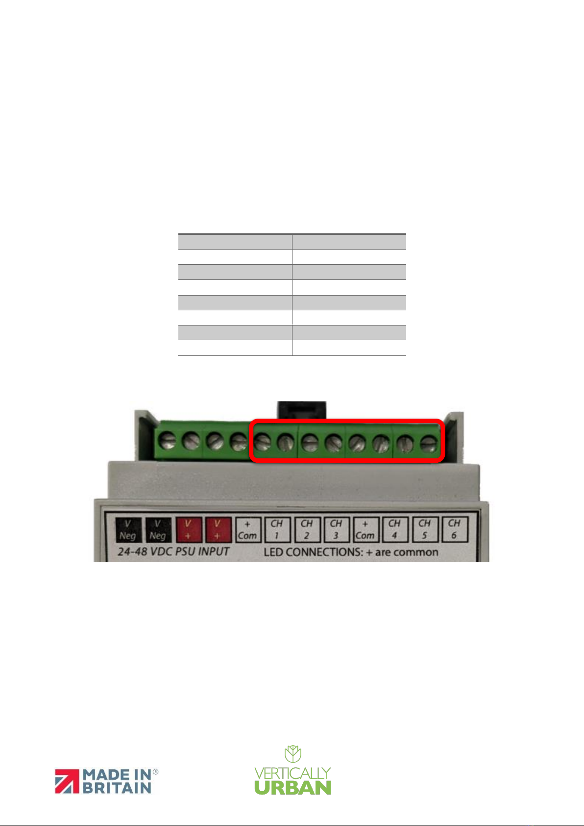
Installing VU-HORTI-BLADE-4CH:........................................................................................................6
DMX Setup ..........................................................................................................................................7
Addressing Drivers with RDM for PWM Output .............................................................................7
Modbus Setup.........................................................................................................................................9
Web Interface ...................................................................................................................................10
Terminating Drivers ..........................................................................................................................11
Cautions: ...............................................................................................................................................12
Scope
This manual will detail the installation and use of a VU SPECTRA DRIVE Driver
Revision History
Approved By
Rev
Date
Comment
Author
A
16/06/19
Document created
JP
B
10/08/21
Changed Format
JP
C
05/04/2022
Added DMX Addressing
JP
Person
Date
Signature
Technical Manager

On-Site Manual
Page 3of 12
Page 3of 12
Overview
The VU SPECTRA DRIVE is a 24-48VDC Din-rail mounted LED Driver; it can be used to provide PWM
control. Installation is covered below.
Figure 1
1
24-48VDC Input/Link Through
2
PWM Channels One to Three
3
PWM Channels Four to Six
4
RJ45 Modbus Input
5
N/A
6
RJ45 Modbus Output
Table 1
1
2
3
4
6
5

On-Site Manual
Page 4of 12
Page 4of 12
Housing: DIN-Rail Case
Material: UL94-V0 PC
Overall Dimensions: 90mm (H) x 106mm (W) x 58mm (D)
Weight: 0.14kg
Mounting: 35mm DIN Rail
Country of Manufacture: United Kingdom
Operating Temperature: 0°C to 40°C
Storage Temperature: -10°C to +50°C
Operating Relative Humidity (max): 80% non-Condensing
IP Rating: IP20 Indoor Use Only

On-Site Manual
Page 5of 12
Page 5of 12
Installation Instructions:
WARNING! Risk of electrical shock. Disconnect power before
servicing or installation.
Please read these instructions carefully before installation and make sure you fully understand them.
Also, pay attention to how the Driver is wired. If you require any further guidance, please contact
Vertically Urban.
Powering the VU SPECTRA DRIVE
Connect the VU SPECTRA DRIVE to a suitable Power Supply using the terminals marked below
(Figure 1). The Power Supply is dependent on the load (See Table 2).
Figure 1
Channel 1
Channel 2
Channel 3
Channel 4
Channel 5
Channel 6
Total
Current
6
6 Amps
6
6
12 Amps
4
4
4
12 Amps
3
3
3
3
12 Amps
2
2
2
2
2
2
12 Amps
Table 2

On-Site Manual
Page 6of 12
Page 6of 12
Installing VU-HORTI-BLADE-4CH:
The VU SPECTRA DRIVE has six PWM channels that can be controlled; they are rated to a maximum
of 6A per channel but only under certain load conditions (refer to Table 1 for loading).
To install a VU-HORTI-BLADE-4CH with the VU-PORWERDRIVE using the six-way starter cable (P/N:
013153) connect to the VU-PORWERDRIVE following the table below.
Starter Cable
VU SPECTRA DRIVE
Yellow
+
Red
CH1
Green
CH2
Blue
CH3
Black
+
White
CH4
N/A
CH5
N/A
CH6
Table 3
Figure 2

On-Site Manual
Page 7of 12
Page 7of 12
DMX Setup
Addressing Drivers with RDM
The drivers need to be addressed to work correctly; this can be done with a DMX testing tool such as
the Swisson XMT-350. Addressing should be done individually and not when the Drivers are
connected together.
Power the VU SPECTRA DRIVE and connect the Swisson XMT-350 to the DMX IN.
Using the arrows navigate to the RDM menu
option and select it.

On-Site Manual
Page 8of 12
Page 8of 12
The Hybrid Drive 6 should be discovered.
Select the DMX START ADDRESS option.
Set the Desired DMX Start address for that
Driver and confirm to save.
NOTE: Each Driver has six PWM channels which correspond to six following DMX addresses assigned
to that Driver. The DMX start address of each Driver should be in the sequence of 6, i.e. if Driver One
has channels 1,2,3,4,5 and 6. Driver Two will start at channel 7 to 12 and so on with no overlapping
channels.

On-Site Manual
Page 9of 12
Page 9of 12
Modbus Setup
Remove the top cover of the Driver and press the button indicated below with the red arrow on the
PCB.
After the button has been pressed, the VU Spectra Drive will create a Wi-
Fi Access Point. The SSID will be PowerDrive_********. Where * is
random characters. The Password is:12345678
As the access point has no internet, you will be prompted to stay
connected. For example, on Android devices, there is a prompt displayed
as shown below. Select yes to stay connected.
On iPhone, it may be necessary to disable Wi-Fi Assist. This is done by going to Settings > Cellular or
Settings > Mobile Data. Then scroll down and tap the slider for Wi-Fi Assist

On-Site Manual
Page 10 of 12
Page 10 of 12
Web Interface
Once you have connected to the PowerDrive, navigate to 192.168.1.1 (in certain circumstances, this
may be 192.168.4.1) in your browser. From here, you can configure the Modbus settings.
Label
Description
Start Register
The first Holding Register
Baud Rate
The Baud rate of the Master
Slave ID
Slave ID of the VU Spectra Drive
Number Of Holding Registers
The quantity of Holding Registers. Each channel
is represented by one Holding Register. The
value of the holding register is value from 0 to
255 with 0 being off and 255 representing 100%
Brightness.
Save
Saves the settings and restarts the Driver

On-Site Manual
Page 11 of 12
Page 11 of 12
Terminating Drivers
After the VU SPECTRA DRIVE has been addressed, they can be wired as required and connected to a
Modbus RTU or DMX data source via the RJ45 port marked Data In. The signal can then be passed
through the VU SPECTRA DRIVE by chaining drivers together sequentially via the Data IN/OUT ports
as shown below up to a maximum of 31 Drivers. The last Driver in the chain must be terminated
using an RJ45 TERMINATOR (Supplied) Spare terminators can be discarded or retained as spares.
The RJ45 cable should be wired as per T-568B Standard with the Orange as Data -, Orange/White as
Data +, and Brown and Brown/White as Ground
MAKE SURE THAT THE DRIVERS ARE ARRANGED IN THE SAME ORDER AS THEY ARE ADDRESSED

On-Site Manual
Page 12 of 12
Page 12 of 12
Cautions:
PLEASE TAKE NOTE OF LUMINAIRE AND DRIVER INGRESS PROTECTION RATING WHEN DECIDING
LOCATION
MAKE SURE ALL CONNECTIONS MADE ARE TIGHT WITH NO LOOSE STRANDS AND WITH AN
APPROPRIATE IP RATING.
DO NOT HOTPLUG. ISOLATE ALL POWER BEFORE ADDING OR REMOVING FITTINGS.
DO NOT REVERSE POLARITY.
ALWAYS ALLOW SUFFICIENT SLACK ON THE SUPPLY CABLE TO REMOVE THE LUMINAIRE FROM ITS
POSITION FOR ANY FURTHER MAINTENANCE
MAKE SURE THE SUPPLY CABLE IS NOT IN CONTACT WITH ANY SHARP OBJECTS; DO NOT LEAVE
THE CABLE OR ANY CONNECTOR EXPOSED TO RAIN/MOISTURE FOR ANY PERIOD.
CAUTION!
•All images are representative and may not be of the product supplied, depending on
options specified when ordering.
•Avoid staring directly into the light beam.
•A certified electrician should install the product following local regulations.
•Take extreme care when working with mains voltages.
•There are no user-serviceable parts inside this unit. Do not attempt any repairs yourself.
Doing so will void your manufactures warranty.
•During operation, the housing may become hot. Avoid touching the unit with bare hands
while in use.
•Do not allow the product to operate in ambient temperatures above the maximum
ambient stated on the datasheet; doing so will void any warranty.
•Do not use aggressive cleaning agents! Any warranty will not cover any chemical damage
to the seals.
•DO NOT “HOTPLUG” THE LED FITTINGS OR DRIVERS, AS THIS WILL INVALIDATE THE
WARRANTY!
Table of contents