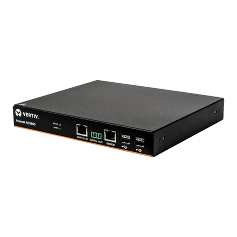
Vertiv Avocent ACS8000 Installation and maintenance instructions

Avocent® ACS800/8000 Advanced Console Server
Installer/User Guide

Vertiv™ | Avocent® ACS800/8000 Advanced Console Server Installer/User Guide
Technical Support Site
If you encounter any installation or operational issues with your product, check the pertinent section of this
manual to see if the issue can be resolved by following outlined procedures.
Visit https://www.VertivCo.com/en-us/support/ for additional assistance.
The information contained in this document is subject to change without notice
and may not be suitable for all applications. While every precaution has been
taken to ensure the accuracy and completeness of this document, Vertiv
assumes no responsibility and disclaims all liability for damages resulting from
use of this information or for any errors or omissions. Refer to other local
practices or building codes as applicable for the correct methods, tools, and
materials to be used in performing procedures not specifically described in this
document.
The products covered by this instruction manual are manufactured and/or sold
by Vertiv. This document is the property of Vertiv and contains confidential
and proprietary information owned by Vertiv. Any copying, use or disclosure of
it without the written permission of Vertiv is strictly prohibited.
Names of companies and products are trademarks or registered trademarks of
the respective companies. Any questions regarding usage of trademark names
should be directed to the original manufacturer.

TABLE OF CONTENTS
1 Introduction 1
1.1 Features and Benefits 1
1.1.1 Access options 1
1.1.2 Web user interface (web UI) 1
1.1.3 IPv4 and IPv6 support 2
1.1.4 Flexible users and groups 2
1.1.5 Security 2
1.1.6 Authentication 2
1.1.7 VPN based on IPSec with NAT traversal 2
1.1.8 Packet filtering 3
1.1.9 SNMP 3
1.1.10 Data logging, notifications, alarms and data buffering 3
1.1.11 Power management 3
1.1.12 Auto discovery 3
1.1.13 FIPS module 3
1.2 Configuration Examples 3
1.2.1 Serial port LEDstatus 6
2 Getting Started 7
2.1 Installation 7
2.2 Turning On the Console System 7
2.2.1 AC power 7
2.2.2 DC power 7
2.3 Configuring a Console System 8
2.3.1 Using Telnet or SSH 9
3 Accessing the Console System via the Web UI 11
3.1 Wizard Mode 11
3.2 Web User Interface Overview for Administrators 13
3.3 Expert Mode 14
3.3.1 Access 14
3.3.2 System Tools 15
3.3.3 System 18
3.3.4 Network 22
3.3.5 IPSec(VPN) Advanced Settings 33
3.3.6 SNMP configuration 33
3.3.7 Ports 34
3.3.8 Pluggable devices 48
3.3.9 Authentication 49
3.3.10 Users accounts and user groups 51
3.3.11 Event notifications 59
3.3.12 Power management 61
Vertiv | Avocent® ACS800/8000 Advanced Console Server Installer/User Guide | i

3.3.13 Sensors 65
3.3.14 Active sessions 67
3.3.15 Monitoring 67
3.3.16 Change password 67
3.4 Web UIOverview for Regular Users 68
Appendices 69
Appendix A: Technical Specifications 69
Appendix B: Zero-touch provisioning 71
Appendix C: Bootp Configuration Retrieval 76
Appendix D: Recovering a Console System Password 77
Appendix E: SSH Setup Allowing RSA Keypair Authentication Instead of a Username/Password 78
Appendix F: Port Information for Communication with the DSView Software 80
Appendix G: Accessing a Console System with a DSView Software Installation via Dial-up 81
Appendix H: Internal Modem 83
Appendix I: Regulatory Information Concerning the Analog Modem Installed in This Product 91
Vertiv | Avocent® ACS800/8000 Advanced Console Server Installer/User Guide | ii

1 INTRODUCTION
The Avocent® ACS800/8000 Advanced Console Server serves as a single point for access and administration of connected
devices, such as serial consoles, modems and power devices. The console server supports secure remote data center
management and out-of-band management of IT assets from any location worldwide.
NOTE: Unless noted, references to a console server refer to all models in the 800/8000 series.
The console server provides secure local (console port) and remote (IP and dial-up) access. The console server runs the
Linux® operating system with a persistent file system in Flash memory that can be upgraded with a local file on a computer
connected to the console server.
Multiple administrators can be logged into the console server at the same time and can use the web user interface (web UI),
the Command Line Interface (CLI utility) or DSView™ 4 management software to access and configure the console server.
NOTE: Unless otherwise noted, all references to DSView software in this document refer to version 4 or greater.
Depending on the model, the console server has either four or eight USB ports to support modems, storage devices, network
adapters, USB hubs and USB console devices. Some models have an SDcard slot to support an additional storage device.
Two network ports support connections to more than one network, or can be configured for Ethernet bonding for redundancy
and greater reliability or network failover support.
For dial-in and secure dial-back with Point-to-Point Protocol (PPP), an optional internal modem can be factory installed or
you can use an external modem connected to either a serial or USBport.
1.1 Features and Benefits
1.1.1 Access options
Secure access is available through the following local (analog console port) and remote (digital IP and dial-up) options:
•LAN/WAN IP network connection.
•Dial-up to a factory-configured internal modem (optional) or a modem connected to one of the serial or
USBports.
•Target device connection. An authorized user can make a Telnet, SSH v2 or Raw connection to a target
device. For Telnet or SSH to be used for target device connections, the Telnet or SSH service must be
configured in the Security Profile that is in effect.
•Console system console connection. An administrator can log in either from a local terminal or from a computer
with a terminal emulation program that is connected to the console port and can use the CLI utility. The CLI
utility prompt (--:- cli->) displays at login.
More than one administrator can log into the console server and have an active CLI or web UI session. All sessions receive
the following warning message when the configuration is changed by another administrator or by the system: The appliance
configuration has been altered from outside of your session. Upon receipt of this message, each administrator needs to verify
that changes made during the session were saved.
1.1.2 Web user interface (web UI)
Users and administrators can perform most tasks through the web user interface (web UI), which can be accessed with
HTTP or HTTPS. The web UI runs in Microsoft® Internet Explorer®, Microsoft® Edge®, Mozilla® Firefox®, Google® Chrome®
and Apple® Safari® on any supported computer that has network access to the console server. The list of supported client
browsers and their versions are available in the release notes.
1

NOTE: When accessing the console server via the web UI, do not disable additional dialogs if prompted by your
browser. Disabling dialogs will disable some functionality of the web UI.
1.1.3 IPv4 and IPv6 support
The console server supports dual stack IPv4 and IPv6 protocols. The administrator can use the web UI or CLI to configure
support for IPv4 addresses only or for both IPv4 and IPv6 addresses. The following list describes the IPv6 support provided
in the console server:
•DHCP
•Dial-in and dial-out sessions (PPP links)
•DSView software integration
•eth0 and eth1 Ethernet interfaces
•Firewall (IP tables)
•HTTP/HTTPs
•Linux kernel
•Remote authentication: Radius, Tacacs+, LDAP and Kerberos servers
•SNMP
•SSH and Telnet access
•Syslog server
NOTE: IPSec is not supported with IPv6.
1.1.4 Flexible users and groups
An account can be defined for each user on the console server or on an authentication server. The admin and root users have
accounts by default, and either can add and configure other user accounts. Access to ports can be optionally restricted
based on authorizations an administrator can assign to custom user groups or individual users. For more information, see
Users accounts and user groups on page 51.
1.1.5 Security
Security profiles determine which network services are enabled on the console server. Administrators can either allow all
users to access enabled ports or allow the configuration of group and user authorizations to restrict access. You can also
select a security profile, which defines which services (FTP, TFTP, ICMP, IPSec and Telnet) are enabled and SSH and
HTTP/HTTPS access. The administrator can select either a preconfigured security profile or create a custom profile. For
more information, see Security on page 18.
1.1.6 Authentication
Authentication can be performed locally, with One Time Passwords (OTP), a remote Kerberos, LDAP, RADIUS, TACACS+
authentication server or a DSView server. The console server also supports remote group authorizations for the LDAP,
RADIUS and TACACS+ authentication methods. Fallback mechanisms are also available.
Any authentication method configured for the console server or the ports is used for authentication of any user who attempts
to log in through Telnet, SSH or the web UI. For more information, see Authentication on page 49.
1.1.7 VPN based on IPSec with NAT traversal
If IPSec is enabled in the selected security profile, an administrator can use the VPN feature to enable secure connections.
For more information, see IPSec(VPN) on page 26.
Vertiv™ | Avocent® ACS800/8000 Advanced Console Server Installer/User Guide
2

1.1.8 Packet filtering
An administrator can configure a console server to filter packets like a firewall. Packet filtering is controlled by chains, which
are named profiles with user-defined rules. The console server filter table contains a number of built-in chains that can be
modified but not deleted. An administrator can also create and configure new chains.
1.1.9 SNMP
If SNMP is enabled in the selected security profile, an administrator can configure the Simple Network Management
Protocol (SNMP) agent on the console server to answer requests sent by an SNMP management application.
The console server SNMP agent supports SNMP v1/v2 and v3, MIB-II and Enterprise MIB. For more information, see SNMP
configuration on page 33.
NOTE: The text files with the Enterprise MIB (ACS8000-MIB.asn) and the TRAP MIB (ACS8000-TRAP-MIB.asn) are
available in the appliance under the /usr/local/mibs directory.
1.1.10 Data logging, notifications, alarms and data buffering
An administrator can set up data logging, notifications and alarms to alert administrators of problems with email, SMS,
SNMP trap or DSView software notifications. An administrator can also store buffered data locally, remotely or with DSView
management software. Messages about the console server and connected servers or devices can also be sent to syslog
servers.
1.1.11 Power management
The console server enables users who are authorized for power management to turn power on, turn power off and reset
devices plugged into a connected power distribution unit (PDU). The power devices can be connected to any serial port.
Authorized users can also monitor and control a connected uninterruptible power supply (UPS)device. For more
information, see Power management on page 61.
1.1.12 Auto discovery
An administrator can enable auto discovery to find the hostname of a target connected to a serial port. Auto discovery’s
default probe and answer strings have a broad range. An administrator can configure site-specific probe and answer strings.
Auto discovery can also be configured through the DSView software.
1.1.13 FIPS module
The 140 series of Federal Information Processing Standards (FIPS) are U.S. government computer security standards that
specify requirements for cryptography modules.
The console server uses an embedded cryptographic module that is based on the FIPS 140-2 validated cryptographic
module (certificate number 1747) running on a Linux ARM platform.For more information, see FIPS module on page 19.
1.2 Configuration Examples
The following graphic and table illustrate a typical Avocent® ACS800/8000 Advanced Console Server configuration.
1 Introduction 3

Figure 1.1 Typical ACS8000 Advanced Console System Configuration
NUMBER DESCRIPTION
1 Power supply (dual power supply shown).
2 Sensor ports for one-wire environmental, smoke, leak, pressure or dry contact sensors.
3 USBports for supported USBdevices.
4 SDcard slot.
5 Connect a phone line to the Modem port for the internal modem.
6Serial ports. Using CAT 5e or CAT6 cables and DB9 or DB25 console adaptors, connect the appropriate serial and power devices to the serial
ports on the console server.
7 Console port and two USBports on the rear of the console server for additional USBdevices.
8
LAN ports. The ports on the left are for copper interface connections. The ports on the right are for fiber interface connections. You may
connect to either or both network ports for redundancy, however only one LAN1 and one LAN2 port may be used at the same time. If both
LAN1 or LAN2 ports are connected, the fiber connection has priority.
Table 1.1 Typical ACS8000 Advanced Console System Configuration Descriptions
The following graphic and table illustrate the multi-protocol ports and LEDs.
Vertiv™ | Avocent® ACS800/8000 Advanced Console Server Installer/User Guide
4

Figure 1.2 Avocent® ACS8000 Multi-Protocol Ports and LEDs
NUMBER DESCRIPTION
1 Multi-protocol ports. These two ports can accept RS422 and RS485 pin-outs in addition to Cyclades and Cisco pin-outs.
2LEDs. The STATUSLEDis green when the console server is fully booted up and initialized. The P1 and P2 LEDs indicate an active power
supply. P1 is green when Power Supply 1 is on. P2 is green when Power Supply 2 is on.
Table 1.2 Multi-Protocol Ports and LED Descriptions
Figure 1.3 Typical ACS800 Advanced Console System Configuration
1 Introduction 5

NUMBER DESCRIPTION
1LEDs. The STATUSLEDis green when the console server is fully booted up and initialized. The Power LEDis green when power is being
supplied to the console server.
2 Connect a phone line to the Modem port for the internal modem.
3 Sensor ports for one-wire environmental, smoke, leak, pressure or dry contact sensors.
4 USBports for supported USBdevices.
5Serial ports. Using CAT 5e or CAT6 cables and DB9 or DB25 console adaptors, connect the appropriate serial and power devices to the serial
ports on the console server. All of the serial ports are multi-protocol and user selectable with RS485, RS422 and RS232 pinouts.
6 Copper LAN ports. You may connect to either or both network ports for redundancy.
7 Console port.
8 Power supply.
Table 1.3 Typical ACS800 Advanced Console System Descriptions
1.2.1 Serial port LEDstatus
Each serial port has two LEDs that illuminate either green or yellow. Green LEDs indicate the status for physical connection
with a serial port, remote connectivity (when applicable)and data transfer. Yellow LEDs indicate whether a serial port is
being monitored along with the alert level (emergency, alert or none)of a monitored target. The following table describes
the meaning of each LEDstatus.
STATE DESCRIPTION FOR GREEN LEDS DESCRIPTION FOR YELLOW LEDS
Off (not illuminated) No physical connection No data buffering
On (solid green or yellow) Device is physically connected to the serial port Data buffering is enabled for the serial port
Slow blink Telnet, SSHor Raw session is active Alert is active
Fast blink TXor RX data activity Emergency
Table 1.4 LED Status Descriptions
Vertiv™ | Avocent® ACS800/8000 Advanced Console Server Installer/User Guide
6

2 GETTING STARTED
2.1 Installation
For information on installing your console server, see the ACS800 or ACS8000 Quick Installation Guide that shipped with
your product.
2.2 Turning On the Console System
Depending on the model, the console server is supplied with single or dual AC or DC power supplies.
WARNING! Always execute the shutdown command through the web UI, CLI or DSView software under the
Overview/Tools node before turning the console server off, then on again. This will ensure the reset doesn't
occur while the file system in Flash is being accessed, and it helps avoiding Flash memory corruptions.
2.2.1 AC power
To turn on a console server with AC power:
1. Make sure the console server is turned off.
2. Plug the power cable into the console server and into a power source.
3. Turn the console server on.
4. Turn on the power switches of the connected devices.
2.2.2 DC power
DC power is connected to a DC-powered console server by way of three wires: Return (RTN), Ground (GND) and -48 VDC.
For redundancy, there are two sets of wires that can be connected to two separate power sources.
WARNING! It is critical that the power source supports the DC power requirements of your console server.
Make sure that your power source is the correct type and that your DC power cables are in good condition
before proceeding. Failure to do so could result in personal injury or damage to the equipment.
The following diagram shows the connector configuration for DC power.
NOTE: DC Power is only available on the ACS8000 console server.
7

Figure 2.1 DC Power Connection Terminal Block
NUMBER DESCRIPTION NUMBER DESCRIPTION
1 Power switch, one for each power source 4 RTN(Return)
2 Connections for the first power source 5 GND (Ground)
3 Connections for the second power source 6 -48 VDC
Table 2.1 DC Power Connection Details
To turn on a console server with DC power:
1. Make sure the console server is turned off.
2. Make sure DC power cables are not connected to a power source.
3. Remove the protective cover from the DC power block by sliding it to the left or right.
4. Loosen all three DC power connection terminal screws.
5. Connect your return lead to the RTN terminal, your ground lead to the GND terminal and your -48 VDC lead to
the -48 VDC terminal and tighten the screws.
6. Slide the protective cover back into place over the DC terminal block.
7. If your console server has dual-input DC terminals, repeat steps 3-6 for the second terminal.
8. Connect the DC power cables to the DC power source and turn on the DC power source.
9. Turn on the console server.
10. Turn on the power switches of the connected devices.
2.3 Configuring a Console System
A console server may be configured at the appliance level through the command line interface accessed through the
CONSOLE or Ethernet port. All terminal commands are accessed through a terminal or PC running terminal emulation
software.
NOTE: To configure the console server using DSView software, see the Avocent® DSView 4.5 Management Software
Installer/User Guide. To configure the console server using the web UI, see Web User Interface Overview for
Administrators on page 13. To configure the console server using Telnet or SSH, see the Avocent® ACS 800/8000
Advanced Console System Command Reference Guide.
To connect a terminal to the console server:
1. Using a null modem cable, connect a terminal or a PC that is running terminal emulation software (such as
HyperTerminal®) to the CONSOLE port on the back panel of the console server. An RJ-45 to DB9 (female)
cross adaptor is provided.
Vertiv™ | Avocent® ACS800/8000 Advanced Console Server Installer/User Guide
8

The terminal settings are 9600 bits per second (bps), 8 bits, 1 stop bit, no parity and no flow control.
2. Turn on the console server. When the console server completes initialization, the terminal will display the login
banner plus the login prompt.
2.3.1 Using Telnet or SSH
An authorized user can use a Telnet or SSH client to make a connection directly to the console of a device if all of the
following are true:
The Telnet or SSH:
•protocol is enabled in the selected security profile
•client is available, and it is enabled on the computer from which the connection is made
To use Telnet to connect to a device through a serial port:
For this procedure, you need the username configured to access the serial port, the port name (for example, 14-35-60-p-1),
device name (for example, ttyS1), TCP port alias (for example, 7001) or IP port alias (for example, 100.0.0.100) and the
hostname of the console server or its IP address.
To use a Telnet client, enter the information in the dialog boxes of the client.
-or-
To use Telnet in a shell, enter the following command:
#telnet [hostname | IP address]
login:username:[portname |device name | TCP Port Alias]
-or-
#telnet [hostname |IP address] TCPPort Alias
login:username
-or-
#telnet IPPort Alias
login:username
To close a Telnet session:
Enter the Telnet hotkey defined for the client. The default is Ctrl ] + q to quit
-or-
enter the text session hotkey for the CLI prompt and then enter exit.
To use SSH to connect to a device through a serial port:
For this procedure, you need the username configured to access the serial port, the port name (for example, 14-35-60-p-1),
TCP port alias (for example, 7001), device name (for example, ttyS1), and the hostname of the console server, IP address or
IP Port alias (for example, 100.0.0.100).
To use an SSH client,
Enter the information in the dialog boxes of the client.
-or-
2 Getting Started 9

To use SSH in a shell, enter the following command:
ssh -l username:port_name [hostname | IP_address]
-or-
ssh -l username:device_name [hostname | IP_address]
-or-
ssh -l username:TCP_Port_Alias [hostname | IP_address]
-or-
ssh -l username IP_Port_Alias
To close an SSH session:
At the beginning of a line, enter the hotkey defined for the SSH client followed by a period. The default is ~.
-or-
enter the text session hotkey for the CLI prompt and then enter exit.
Vertiv™ | Avocent® ACS800/8000 Advanced Console Server Installer/User Guide
10

3 ACCESSING THE CONSOLE SYSTEM VIA THE WEB UI
Once you’ve connected your Avocent® ACS800/8000 Advanced Console Server to a network, you can access the console
server with its web user interface (web UI). The web UI provides direct access to the console server via a graphical user
interface instead of a command-based interface.
NOTE: For a new console server using factory defaults, LAN1 attempts to obtain an IPaddress using DHCP, and LAN2
has a static IPaddress of 192.168.161.10. Use LAN2 for initial configuration or use the Console port to discover the IPv4
DHCP-assigned address for LAN1.
NOTE: For instructions on accessing the console server via the CLI or DSView software, see the Avocent®
ACS800/8000 Advanced Console Server Command Reference Guide or the Avocent® DSView 4.5 Management
Software Installer/User Guide.
3.1 Wizard Mode
The Wizard mode is designed to simplify the setup and configuration process by guiding an administrator through the
configuration steps. An administrator can configure all ports in the CAS Profile and set the Security Profile, Network and
Users Settings using the Wizard.
By default, the first time an administrator accesses the console server through the web UI, the Wizard displays. Subsequent
log-ins open in Expert mode, and once the console server has been configured, Expert mode becomes the default mode. An
administrator can toggle between Expert and Wizard modes by clicking the tab bar on the web UI administrator screen.
The following image shows a typical screen when an administrator is in Wizard mode.
11

Figure 3.1 Wizard Screen
The following procedures describe how to configure the console server from the Wizard.
To configure security parameters and select a Security Profile:
1. Select the Security link in the content area.
2. Select the desired Security Profile. If using a Custom Security Profile, click the checkboxes and enter values as
needed to configure the services, SSH and HTTP and HTTPS options to conform with your site security policy.
3. Pluggable devices, which include devices connected to SDcard slot and USBports, are disabled by default. To
enable them, check the Enable Pluggable Device Detection box. Storage devices (SDcard and
USBstorage)are enabled by default when Pluggable Device Detection is enabled. To disable this subset of
pluggable devices, clear the Enable Pluggable Storage Devices box. Pluggable devices also include the 1-Wire
Sensor port which is enabled by default. To disable the 1-Wire Sensor port, uncheck the Enable 1-Wire Support
box.
4. Under the Bootp Configuration Retrieval heading, uncheck the box(es)to disable Bootp configuration retrieval
and/or live configuration retrieval.
5. If you are not using DSView software to manage the appliance, uncheck the Allow Appliance to be Managed by
DSView box.
6. Click Next to configure the Network or click the Network,Ports or Users link to open the appropriate screen.
To configure network parameters:
1. Select the Network link in the content area.
2. Enter the Hostname, Primary DNS and Domain in the appropriate fields.
Vertiv™ | Avocent® ACS800/8000 Advanced Console Server Installer/User Guide
12

3. Select the IPv4 or IPv6 method for the ETH0 interface. If using Static, enter the Address, Mask and Gateway in
the appropriate fields.
4. Enable or disable LLDP(Link Layer Discovery Protocol).
5. Enable or disable IPv6 support.
6. Click Next to configure ports or click on the Security,Ports or Users link to open the appropriate screen.
To configure Ports:
1. Select the Ports link in the content area.
2. Check the box to enable all ports.
3. Use the appropriate drop-down menus to select the values for the RJ45 Pin-Out, Speed, Parity, Data Bits, Stop
Bits, Flow Control, Protocol, Authentication Type and Data Buffering Status and Data Buffering Time Stamp.
4. Select the Data Buffering Type. If using NFS, enter the NFS Server and NFS Path information in the appropriate
fields.
5. Click Next to configure users or click on the Network,Security or Users link to open the appropriate screen.
To configure users and change the default user passwords:
WARNING! For security reasons, it is recommended you change the default password for both root and admin
users immediately.
1. Select the Users link in the content area.
2. Click a username (admin or root) and enter the new password in the Password and Confirm Password fields.
-or-
3. Click Add to add a user. Enter the new username and password in the appropriate fields.
4. (Optional) To force the user to change the default password, select the User must change password at next
login checkbox.
5. Assign the user to one or more groups.
6. (Optional) Configure account expiration and password expiration.
7. Click Next.
8. Repeat steps 3-7 as needed to configure new user accounts and assign them to default groups.
NOTE: By default, all configured users can access all enabled ports. Additional configuration is needed if your site
security policy requires you to restrict user access to ports.
9. Click Save, then click Finish.
3.2 Web User Interface Overview for Administrators
NOTE: For an overview of the web user interface (UI)for regular users, see Web UIOverview for Regular Users on
page 68.
To log into the web UI:
1. Open a web browser and enter the console server IP address in the address field.
2. Log in as either admin with the password avocent or as root with the password linux.
The following figure shows a typical web UI screen for an administrator.
3 Accessing the Console System via the Web UI 13

Figure 3.2 Administrator Web UI Screen
NUMBER DESCRIPTION
1
Top option bar. The name of the appliance and of the logged
in user appear on the left side. Refresh, Print, Logout and Help
buttons appear on the right.
2Tab bar. Displays whether the admin is in Expert or Wizard
mode.
3
Side navigation bar. Menu options for configuration, viewing
of system information and access to devices. The options
change based on user rights.
4Content area. Contents change based on the options selected
in the side navigation bar.
Table 3.1 Web UI Screen Areas
3.3 Expert Mode
The following tabs are available in the side navigation bar of the web UI when an administrator is in Expert mode.
3.3.1 Access
All the devices connected to the console server can be viewed from the Access icon.
To view and connect to devices using the web UI:
1. Select Access in the side navigation bar. The content area displays the name of the console server and a list of
names or aliases for all installed and configured devices the user is authorized to access.
2. Select Serial Viewer from the Action column to open a connection to the selected serial port.
-or-
Select Appliance Viewer from the Action column to open a connection to the console server.
NOTE: The HTML5 viewer is the default viewer to open; however, if an administrator has selected the JNLPviewer,
the Java® applet viewer appears.
Vertiv™ | Avocent® ACS800/8000 Advanced Console Server Installer/User Guide
14

3. If you are not automatically logged in, log in when prompted.
3.3.2 System Tools
Click System Tools to display icons which can be clicked to reboot or shut down the console server, upgrade the console
server’s firmware, save or restore its configuration or open a terminal session with the console server.
Upgrading firmware
The console server supports the storage of two firmware images. As the firmware is upgraded, the image not currently
running will be overwritten with the new firmware. The latest firmware can be downloaded from the Vertiv website and
accessed by the console server using a File Transfer Protocol (FTP), Secure File Transfer Protocol(SFTP)or Secure Copy
Protocol (SCP)server. Firmware can also be downloaded via a web browser from the user's local machine.
To view the console server's current firmware version, from the sidebar of the Expert tab, click System-Information.
To upgrade a console server's firmware:
1. From http://www.VertivCo.com, browse to the product updates section and find the firmware for your console
server.
2. Save the new firmware to a server accessible via FTP,SFTPor SCP, or to your desktop.
3. From the sidebar of the console server's web UI, click System Tools, then click Upgrade Firmware.
4. Download the file from theserver you selected in step 2.
a. Click the radio button next to Remote Server, then use the drop-down menu to select the protocol of the
server where you saved the file.
b. Enter the IPaddress for the server where the firmware is saved in the appropriate field.
c. Enter the username and password for the server in the appropriate fields.
d. Enter the file directory where the firmware is saved and the filename for the firmware in the appropriate
fields.
-or-
Download the file from your desktop by selecting My Computer.
a. Type the filename for the new firmware or click Browse to open a window and browse to the file.
5. Click Download. The console server will download the firmware from the specified site and will display a
message when the download is complete.
6. Click Install.
7. Once the new firmware is installed, reboot the console server.
Configuration files
An administrator can create a backup image of the console server's configuration. During creation, no changes should be
made to the configuration. The backup configuration file may be uploaded to a remote server, stored on a console server
local file or saved to the web user's computer. Configuration files can be saved as a compressed file, CLIscript or XMLfile.
To save the current configuration file:
1. From the sidebar of the Expert tab, click System Tools.
2. Click Save Configuration.
3. Use the drop-down menu to select the file format.
4. Upload the file to a remote server.
3 Accessing the Console System via the Web UI 15

a. Click the Remote Server radio button, then use the drop-down menu to select the protocol of the server
where you want to save the file.
b. Enter the IPaddress for the server where the file will be saved in the appropriate field.
c. Enter the username and password for the server in the appropriate fields.
d. Enter the file directory where the configuration file will be saved and the filename in the appropriate
fields.
-or-
Save the file locally by clicking the Local File radio button, then enter the filename.
NOTE: The filename can include the full path to where the file will be saved. Specifying the full path permits the file to
be saved to a USBstorage device that is mounted, for example /media/sda1/filename. If the full path is not specified,
the file is written to /mnt/hdUser/backup/<filename>.
-or-
Save the file to your computer by clicking the My Computer radio button. The file will be saved in your
Downloads folder.
5. Click Save.
To restore a previous configuration:
1. From the sidebar of the Expert tab, click System Tools.
2. Click Restore Configuration.
3. Restore the file from a remote server.
a. Click the Remote Server radio button, then use the drop-down menu to select the protocol of the server
where the configuration file is saved.
b. Enter the IP address of the server where the file is saved in the appropriate field.
c. Enter the username and password for the server in the appropriate fields.
d. Enter the path and filename for the configuration file.
-or-
Restore from a local file by clicking the Local radio button and entering the filename.
-or-
Restore the file from your computer by clicking the My Computer radio button, then browse to where the file is
saved on your computer and click Open.
4. Click Restore.
Configuration integrity
In order to ensure configuration integrity, the console server permits an administrator to generate and verify a digital
signature (MD5)of the console server's configuration. The console server compares its MD5 checksum value against a
known MD5 checksum value to verify its configuration and keep it protected from corruption.
An administrator can specify a running configuration as trusted and instruct the console server to generate an MD5 tag for
the trusted configuration. An administrator can also verify the configuration by comparing it to another known or trusted
configuration. The console server will declare the configuration to either be Unchanged or Modified after the verification is
complete.
Vertiv™ | Avocent® ACS800/8000 Advanced Console Server Installer/User Guide
16
Other manuals for Avocent ACS8000
3
This manual suits for next models
1
Table of contents
Other Vertiv Network Hardware manuals
Popular Network Hardware manuals by other brands

Patton electronics
Patton electronics 2888 Product brief

ATTO Technology
ATTO Technology FibreBridge 2370E Specifications

FieldServer
FieldServer X-25 Startup guide

Magma
Magma PCI Expansion System PE6R4 user manual

IEI Technology
IEI Technology PUZZLE-9030 Series user manual

GNS
GNS NR31P4-4 Quick operation guide