VERTON Everest 6 User manual

Everest 6 User Manual

REVISION HISTORY
VERSION NO. DATE UPDATED REVISION AUTHOR SUMMARY OF MAJOR CHANGES MADE
1.0 7-Nov-2019 Mitchell Bourne Initial Release
2.0 10-Feb-2020 George Gett R20 changed to Everest 6
3.0 3-July-2020 George Gett Updates to transportation and long-term storage.
Warning Labels and safety sections refined.
4.0 16-Oct-2020 George Gett Troubleshooting guide updated
5.0 18-May-2021 Joel Kok Maintaining a safe yaw rate
DOCUMENT REFERENCES
N0. DESCRIPTION REFERENCE
1 VERT_0005 Everest 6 Rigging Arrangement Revision 1
2 VERT_0010 Sound Pressure Measurement Revision 1
3 VERT_0052 Operating Temperature Justification Revision 1
4 VERT_0002 Basic Maintenance Manual Revision 1
5 VERT_0013 Advanced Maintenance Manual Revision 1
6 VERT_0003 Packing Guidelines Revision 1
VERT_0014_User_Manual_04 Confidential © Verton 2021 2

2. Declaration of Conformity 4
3. General Information 5
3.1. Purpose and Scope 5
3.2. Disclaimer 5
3.3. Points of Contact 5
4. Safety 6
4.1. Limitations of Use 6
4.2. Warning Symbols and Notes 6
4.3. Training and Competence 7
4.4. Noise 7
4.5. Important Note on the Everest 6 Stop
Function and Loss of RadioLink 7
4.6. General Hazard Reduction 7
5. Operation 8
5.1. General Assembly and Rigging 8
5.2. Unit Control 9
5.2.1 Starting the Unit 10
5.2.2 Safe Manoeuvring of the Load 11
5.2.3 Maintaining a safe yaw rate 11
5.2.4 Shutting down the Unit 12
5.2.5 Gimbal Reset 12
5.2.6 Remote Shutdown 12
5.3. Information Labels 13
6. Information Display 14
6.1. Display Screen 15
6.1.1. Overview Page 15
6.1.2. Unit Control Page 16
6.2. Machine States 16
7. Operating Environment 17
8. Looking After the Unit 18
8.1. Maintenance 18
8.2. Storage Instructions 18
8.2.1. Short Term Storage 18
8.2.2. Long Term Storage 19
9. Transportation 20
9.1. General 20
9.1.1. Purpose and Scope 20
9.1.2. Responsibility
and Reliability 20
9.1.3. Additions, Exceptions,
and Modifications 20
9.2. Hazardous Materials 20
9.3. Moving and Relocating the
Everest 6 Via Forklift 21
9.4. Packing for Shipping 22
9.4.1. Battery 22
9.4.2. Packing and Loading
recommendations 22
10. Troubleshooting Guide 23
10.1. General Information 23
10.2. Remote Errors 24
10.3. Connectivity Errors / Problems 24
10.4. Start-up / Shutdown Errors 26
10.5. Charging Errors 27
10.6. Irregular Machine Behaviour 28
11. Customer Delivery Acceptance Test 29
12. Load Suitability Lookup Table 30
Table of
Contents
VERT_0014_User_Manual_04 Confidential © Verton 2021 3

2. Declaration of Conformity
EC Declaration of Conformity (DoC)
In accordance with:
EC Machinery Directive 2006/42/EC (Annex II 1A)
EC Electromagnetic Compatibility 2014/30/EU (Annex IV)
We herewith declare, under our sole responsibility that the:
Product Name Everest Series a.k.a E-Series
Model Number E6
Serial Number
Manufacturer Verton Technologies Australia, 5 Gardner Close,
Milton, Queensland, 4064, Australia
When used in accordance with the manufacturer’s instructions,
conforms with the applicable essential health and safety requirements
of the Machinery Directive and conforms with the protection
requirements of the EMC Directive by virtue of its design, construction
and assessment.
In support of this declaration the subject machine has been evaluated
as complying with the following:
a. The Machinery Directive (Annex I), by compliance with the
applicable clauses of the following harmonised standards; EN
ISO 12100, EN 13155, EN 60204-1 and associated standards
(Technical File for Compliance with 2006/42/EC [VERT_0054
Machinery Technical File_04] dated 06 July 2020 is held by the
manufacturer). Certificate of Conformity 191010GRc issued by
Projects etc Pty Ltd.
b. The EMC Directive (Annex II), by application of EMC Assessment
Procedure ref VERT_0017 EMC Assessment Procedure dated
12 September 2019. (Technical Documentation for Compliance
with 2014/30/EU VERT_0055 EMC Technical File_03 dated 06
July 2020 is held by the manufacturer). Certificate of Conformity
191010GRd issued by Projects etc Pty Ltd refers.
The “Person Authorised to Compile the Technical File” (TF) under the
EU Machinery Directive (2006/42/EC) and “Authorised Representative”
under the EU EMC Directive (2014/30/EC) under Contract VERT_0018_
CE Nominated Person Contract Dated 2018 October 25 is:
Craig Millis, General Manager
Verton Europe BV
Registered address is Bulgersteyn 7241, Rotterdam 3011 AB
If the equipment is modified without the agreement of the
undersigned, this declaration becomes invalid.
4
VERT_0014_User_Manual_04 Confidential © Verton 2021

3.1. PURPOSE AND SCOPE
The contents of this manual detail instructions for the transportation
and operation of the Everest 6 smart lifting beam.
Every care has been taken to ensure the accuracy of information
contained in this manual, but no liability can be accepted for any
errors or omissions. Due to ongoing product development, Verton
Australia reserves the right to change without notice, any product
details including specification, appearance, and performance.
Strict compliance with all local and national laws, regulations and
practices regarding the safe operation and maintenance of the
Everest 6 is necessary to assure the personal safety of those working
on, or around, this machine.
3.2. DISCLAIMER
It is a requirement of use of this machine that all aspects of
transporting, rigging, operation, and maintenance are thoroughly risk
assessed by the site owner. Compliance with local laws regulations
and practices is required for safe use of this machine.
Verton Australia provides instructions, training, warnings, and notes
regarding the use of the Everest 6. Consequently, Verton Australia for
itself, its directors, ocers, employees and agents expressly disclaims
any liability whatsoever, whether it be for personal injury, death,
property damage, economic loss or any other loss by any person or
entity of the Everest 6.
3.3. POINTS OF CONTACT
If there are any questions related to the operation and use of the
Everest 6, you can contact Verton via phone on +61 7 3217 5816 or
alternatively you can email Verton support at support@verton.com.au
3. General Information
5
VERT_0014_User_Manual_04 Confidential © Verton 2021

4.1. LIMITATIONS OF USE
The Everest 6 has been specifically designed to lift and rotate
suspended loads of up to but no greater than 20T. Any other uses are
not recommended or warranted by Verton Australia.
4.2. WARNING SYMBOLS AND NOTES
Actions and items detailed throughout this user manual may expose the
user to various levels of risk. These items and sections have been clearly
labelled throughout this document and are indicated by the following:
Additionally, warning labels located on the Everest 6 provide
information about the hazards related to operation of the unit. An image
and description of each on beam warning label is provided in Table 1.
Table 1: Everest 6 machine warning labels
LABEL DESCRIPTION
Unit contains moving parts;
risk of injury
Stand clear of
suspended loads
Unit contain electrical
components; risk of
electric shock
4. Safety
CAUTION – Failure to heed these cautions may
result in damage to equipment or components
WARNING – Failure to heed these warnings may
result in personal injury or death
6
VERT_0014_User_Manual_04 Confidential © Verton 2021

4.3. TRAINING AND COMPETENCE
All personnel using or associated with the use of this equipment
must be competent and trained by Verton Australia itself or a third
party authorised to deliver training on behalf of Verton Australia.
At a minimum:
1. Read and understand this manual and all safety warnings.
2. Familiarisation with machine functions and limitations.
3. Be competent and trained in the risks of lifting equipment,
practises, and planning.
4. Know and be trained in the use of the emergency stop function
fitted to the Everest 6 (See Section 4.5)
4.4. NOISE
As the units contain moving parts, sound pressure generation
should be taken into consideration. Testing results show that a
maximum sound pressure of 78.5dBA was taken from the unit during
operation1. While this is below the requirement for ear protection,
general safety precautions such as PPE should be used to minimise
long term exposure.
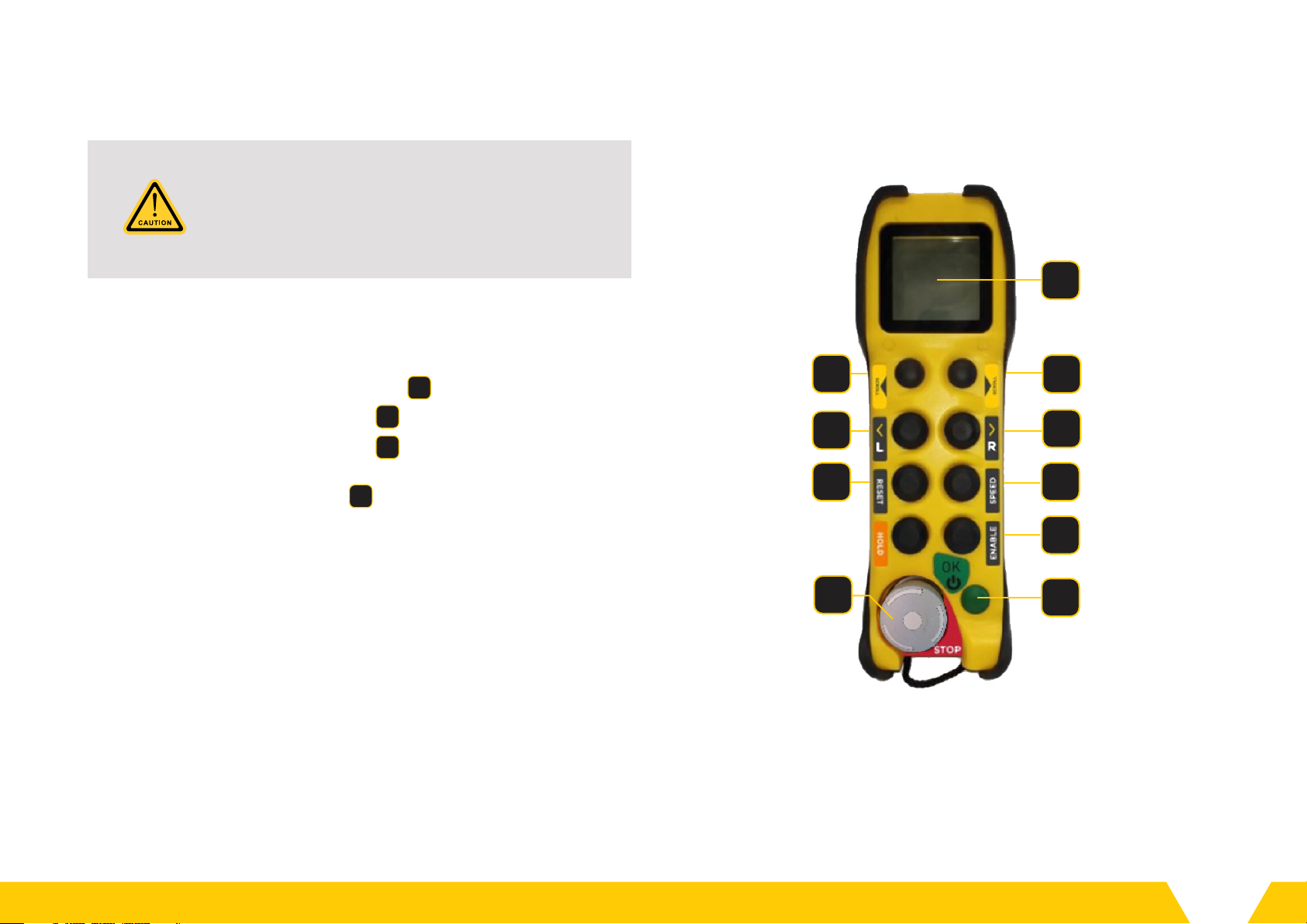
4.5. IMPORTANT NOTE ON THE EVEREST 6 STOP
FUNCTION AND LOSS OF RADIO LINK
4.6. GENERAL HAZARD REDUCTION
General hazard reduction whilst using the Everest 6 can be
accomplished by observing the following items:
• Only qualified dogmen and riggers shall use the unit.
• Operators must be trained, competent and authorised for a
specific operation.
• Inspect the unit prior to use and do not use the lifting beam
if it is damaged.
• Test operation of the unit before use. Do not use if faulty.
• Do not remove any cover panels unless authorised.
• Do not cover the air-vents while the beam is in operation as
overheating may occur.
Whilst all local laws, regulations and practises must be satisfied whilst
completing any lifting operation, additional safety considerations must
be made to reduce the general lifting operational hazards whilst using
the Everest 6. These items include:
• Observe all the normal lifting and rigging safety precautions.
• Do not exceed the SWL of the unit.
• Avoid rough landings or collisions as internal components
may be damaged.
• Cease operation immediately if the unit is damaged or faulty.
• Do not stand under the suspended unit or move the unit
over personnel.
• Avoid rotating the beam close to the ground or around
other objects.
• Avoid bodily contact with the beam, especially if the unit
is operating in a hot environment.
IMPORTANT NOTE: The Remote Shutdown / STOP button IS NOT
an Emergency Stop button in the conventional sense. The stop
function, or loss of radio communications will prevent the Verton
beam applying any torque to the lifting arrangement.
1VERT_0010 Sound Pressure Measurement
7
VERT_0014_User_Manual_04 Confidential © Verton 2021

5.1. GENERAL ASSEMBLY
AND RIGGING
The unit’s general assembly is
displayed in Figure 2 below. This will be
referenced throughout the document.
To correctly rig the unit for a load,
please refer to the relevant rigging2
documentation provided.
5. Operation
Figure 2: General Assembly Drawing
END FRAME
LIFTING LUG
BOTTOM BEAM
LOCKABLE BATTERY ISOLATOR
SWITCH
LIFTING
POINTS
2VERT_0005 Everest 6 Rigging Arrangement
8
VERT_0014_User_Manual_04 Confidential © Verton 2021

5.2. UNIT CONTROL
General operation of the machinery utilises the use of a hand-held
remote control to send user commands to the unit. As described in
Table 2 below, the remote control contains the following elements.
Table 2: Controller Button Descriptions
DESCRIPTION OPERATION
1Display Screen Displays the current status of the unit
2Remote Shutdown Press to shut down the beam
3Battery Pack Must be fitted for operation
MRemote Connect Connects controller to the unit
F1 Motor Enable Enables the flywheel motors
F2 Gimbal Reset Resets gimbals to neutral position
F3 Speed Select Selects the motor RPM
F4 Left Rotates the beam left
F5 Right Rotates the beam right
N1 Page Left Changes the display page left
N2 Page Right Changes the display page right
The controller is connected to the unit utilising RF communications.
An encryption method is used ensuring unit and control security. The
range of the controller is approximately 300 metres for unobstructed
line of sight, and generally 150-170 metres otherwise.
Figure 3: Controller Overview
N2
1
F5
F3
3
F1
M
2
F2
F4
N1
9
VERT_0014_User_Manual_04 Confidential © Verton 2021

5.2.1. STARTING THE UNIT
1. Disconnect the battery charger from the unit.
2. Move the isolation power switch (refer to Figure 2) on the unit to
the ON position.
3. Release the Remote Shutdown button 2on the remote control.
4. Press the Remote Connect button M.
5. Press the Remote Connect button Magain to begin a connection
with the unit.
6. Press the Motor Enable button F1 to begin spinning the flywheels.
Wait until the roll speed reaches the selected motor speed.
*Note: The flywheels will continue to spin down for several minutes
after power shuto.
ENSURE THE BEAM IS IN A READY STATE (ALL
HATCHES ARE CLOSED AND ALL COMPONENTS
ARE CORRECTLY INSTALLED INTO THE BEAM)
WHEN THE POWER ISOLATION SWITCH IS
PLACED INTO THE ON STATE.
N2
1
F3
F1
M
2
F2
F4
N1
Figure 3: Controller Overview
F5
10
VERT_0014_User_Manual_04 Confidential © Verton 2021

5.2.2. SAFE MANOEUVRING OF THE LOAD
1. Press the Gimbal Reset button F2 to roll the gimbals to a
neutral position.
2. Press the Speed Select button F3 to select the desired motor
speed for the planned operation.
3. Connect the load to the beam and raise the beam with the crane.
4. Press the Left button F4 to rotate left, or the Right button F5
to rotate right. In general, it is recommended that a “Tap-Tap”
technique is used when pressing the Left F4 and Right F5 buttons.
(see Section 5.2.3). *
5. To slow down and/or stop rotation, press the Left or Right button
(F4 / F5 ) opposite to the current direction of rotation.
6. Once the load is lowered into desired position, disconnect the load
from the beam.
7. Press the Gimbal Reset button F2 to roll the gimbals to a neutral
position.
*Note that there are instances when the “Tap-Tap” technique may
not be appropriate, namely when the inertia is large relative to the
capacity of the Verton Beam - e.g. an Amber load (see Section 12 Load
Suitability Table). In these cases, longer button press duration on the
Left/Right buttons are more ecient than “Tap-Tap”, where excessive
short inputs may result in the unit reaching maximum gimbal limit
quicker.
5.2.3. MAINTAINING A SAFE YAW RATE
(“TAP-TAP” TECHNIQUE)
1. For safety reasons and to minimize unnecessary dynamic loads, it
is desirable to keep the yaw rate of the Verton Beam (with the load
hung underneath) at or under 4 deg/s.* (For reference, the Seconds
Hand on a clock sweeps at 6 deg/s)
2. In general, it is recommended that a “Tap-Tap” technique is used
when pressing the Left F4 and Right F5 buttons.
3. When going Left, press and hold down the Left F4 button for
no longer than 1 - 2 seconds (considered a “Tap”), and gauge
the yaw rate of the Verton beam. If the beam is still far below 4
deg/s, repeat the “Tap” (pressing down and holding for no more
than 1 - 2 seconds), possibly for several times, until the yaw rate is
approximately 4deg /s. Once this yaw rate is reached (or slightly
exceeded), allow the Verton beam to “coast” to its intended
orientation (i.e. no further “Taps” required unless the yaw rate starts
to drop).
* Note that the Verton beam comes with an inbuilt safe-guard where
the yaw-rate is automatically limited to 4deg/s – 6deg/s. Note that the
Tap-Tap technique should still be observed regardless of the presence
of this safeguard.
ALWAYS USE AUTHORISED LIFTING TECHNIQUES,
RIGGING, EQUIPMENT AND PLANNING
THROUGHOUT ALL LIFTING OPERATIONS.
11
VERT_0014_User_Manual_04 Confidential © Verton 2021

5.2.4. SHUTTING DOWN THE UNIT
1. Press the Motor Enable button F1 to disable the flywheel motors.
This will ensure the flywheel energy is regenerated back into the
battery.
2. Once the remote-control reports zero RPM for both motors push
the Remote Shutdown button 2to disable the system.*
3. Turn the Battery Isolator switch on the main unit to the
OFF position.
4. Recharge the unit by connecting the electrical charging cable
(if required).
5. Recharge the remote controller by removing rechargeable battery
pack 3and inserting into charging unit (if required).
*Note: The flywheels will continue to spin down for several minutes
after power shuto
5.2.5. GIMBAL RESET
Resetting flywheel roll angles brings the gyroscopes back to their
neutral positions (0°). Resetting this angle improves performance and
should be completed before every lift (where possible).
1. Lower the beam to a safe position on the ground.
2. Press the Gimbal Reset button F2 . The gimbals will rotate, one side
at a time, back to the neutral position.
3. Continue use or shut down the beam when this operation is complete.
5.2.6. REMOTE SHUTDOWN
The Remote Shutdown button 2is only be used to shut down the
unit once the lift has completed. The Remote Shutdown button will
disconnect power to the unit immediately. If this button is de-pressed
during a lift, the unit and suspended load may continue to rotate under
their own inertia until power is reapplied by restarting the Verton unit or
until wind or hook friction brings the lift assembly to a complete halt.
PERFORMING A GIMBAL RESET WHILST THE
EVEREST 6 IS SUSPENDED IN THE AIR MAY
RESULT IN AN UNCOMMANDED YAWING MOTION.
12
VERT_0014_User_Manual_04 Confidential © Verton 2021

Table 3: Table of Information Labels
INFORMATION LABELS DESCRIPTION
Indicator for the direction of the
battery isolator switch.
Main plate axed to the unit
which describes the input
voltage and current for the mains
supply. It has the working load
limit (WLL) capacity and the tare
weight of the unit.
Plate adjacent to power input
5.3. INFORMATION LABELS
Information labels provide information
about the operation of the unit. An image
and description of each information label is
provided in Table 3.
13
VERT_0014_User_Manual_04 Confidential © Verton 2021

6.1. DISPLAY SCREEN
The Display Screen shown as item 1 in Figure 3 (refer page 4) displays
a variety of real-time information about the operation of the unit,
including battery level, unit heading, gimbal angles and motor speed.
The Display Screen has three pages; to navigate between these pages,
use the Page Left N1 and Page Right N2 buttons.
6.1.1. OVERVIEW PAGE
The Overview Page, shown in Figure 4 below, primarily displays current
machine state (shown in Figure 4 as IDLE) and current battery level
(shown at 50%).
Machine states are further explained in section 4.3.
The page also shows the current average RPM of the units roll motors
(shown above as 1550RPM).
The bottom part of each page also provides visual confirmation of
instructions given to the unit (rotate left, rotate right, gimbal reset,
speed select, hold, motor enable).
This page is most useful for monitoring the overall machine state
and should be checked regularly throughout unit operation.
6. Information Display
Figure 4:
Remote Display –
Overview Page
14
VERT_0014_User_Manual_04 Confidential © Verton 2021

6.1.2. UNIT CONTROL PAGE
The Unit Control Page, shown in Figure 5 adjacent, displays the
roll angle of each gimbal, as well as the current motor RPM state
(shown as Low – 1800RPM).
Possible motor states are:
• Low – 1800RPM,
• Med – 2500RPM and
• High – 3000RPM.
Note it is possible that the current RPM of the two motors may be
higher or lower than the specified motor state. For example, if the
motor state is decreased from Medium to Low it will take several
minutes for the motor speed to reduce accordingly.
The roll angle of the two gimbals will be in the range -90 to +90
degrees. If the roll angles diverge significantly (more than 10 degrees)
the gimbals should be returned to a neutral position by pressing the
Gimbal Reset button ( F2 ).
This page is most useful for managing the gimbal angle while
orienting a load. It is also useful to monitor progress when the unit
is resetting gimbals.
Figure 5:
Remote Display –
Gimbal Page
15
VERT_0014_User_Manual_04 Confidential © Verton 2021

6.2. MACHINE STATES
The state word displayed on the controller represents the current
running state that the unit is operating in. All available unit states
are displayed in Table 4 below, with the related state word being
displayed on the controller’s screen.
Table 4: State Descriptions
STATE WORD STATE DESCRIPTION
WAIT FOR SPIN The machine is waiting for the spin motors
to be enabled.
SPIN-UP The machine is waiting for the spin motors
to each time the desired user speed.
READY
The machine is ready for use at minimum
operating speed. The spin motors may not
yet have reached desired operating speed.
IDLE The machine is now in an idle state and will
begin to reduce power draw.
LEFT The Left button ( F4 ) is pressed.
RIGHT The Right button ( F5 ) is pressed.
RESET ROLL
POSITIONS
The machine is resetting the gimbals to
neutral position.
FAULT The system has detected a fault. In this case
an alarm and/or stop bit will be displayed.
16
VERT_0014_User_Manual_04 Confidential © Verton 2021

The allowable temperature range of the beam is determined by the
rated range of individual components3, the conclusions of which are
summarised in Table 5 below.
Table 5: Unit Temperature Range
LOW (CELSIUS) HIGH (CELSIUS)
OPERATING
TEMPERATURE -5° 36°
CHARGING
TEMPERATURE -5° 40° (Ambient)
Operations outside these temperatures can be achieved with
calibration and modification.
3VERT_0052 Operating Temperature Justification
7. Operating Environment
17
VERT_0014_User_Manual_04 Confidential © Verton 2021

8.1. MAINTENANCE
In general, maintenance should be completed on both a short and
long-term basis. Short term maintenance includes daily visual checks
and general operational maintenance, further specified in the Basic
Maintenance Manual provided4.
For long term maintenance, certain components require a mix
of recurring visual inspections and occasional replacement for
pro-active maintenance. For these components, general lifecycle/
duration and replacement frequency is specified, with general
long-term maintenance in the Advanced Maintenance Manual5.
8.2. STORAGE INSTRUCTIONS
8.2.1. SHORT TERM STORAGE
Prior to storage, ensure that the Battery Isolator switch is placed into
the OFF position as per Figure 7.
Although the Everest 6 is designed and certified to be IP-55 water
and dust resistant, it is strongly recommended that the beam is stored
in a covered location (e.g. warehouse) and kept protected from the
elements when not in use (e.g. at the end of each work day).
8. Looking After the Unit
4VERT_0002 Basic Maintenance Manual
5VERT_0013 Advanced Maintenance Manual
Figure 7: Everest 6 Battery Isolator
18
VERT_0014_User_Manual_04 Confidential © Verton 2021

8.2.2. LONG TERM STORAGE (1 MONTH OR MORE WITHOUT USE)
Prior to storage, ensure that the Battery Isolator switch and the QB1
circuit breaker are both placed into the OFF position. For the locations
of both of these switches please refer to Figure 7 and Figure 8.
Ensure the battery is charged to 100% capacity prior to long term
storage. To ensure the health and longevity of the battery system,
it is required that the machine be placed on charge for a 48-hour
period at least once per every month of long-term storage.
Prior to charging, ensure the Battery Isolator switch and the BMS
breaker (QB1) are both placed into the ON position. If the BMS display
does not turn on (see Figure 7), then the battery must be revived.
If the battery must be revived please contact Verton Australia (see
Section 3.3) immediately.
For long term storage, it is required that the beam be stored in a covered
location and kept from prolonged exposure to both sun and rain.
FAILURE TO ROUTINELY RECHARGE THE
BATTERY WILL RESULT IN SIGNIFICANT
DAMAGE TO THE BATTERY SYSTEM.
DO NOT ATTEMPT TO REVIVE THE BATTERY
UNLESS INSTRUCTED TO DO SO
BY VERTON DIRECTLY.
Figure 8:
Location of the QB1
Circuit Breaker
Figure 9:
BMS Display
On O
↑ ↓
19
VERT_0014_User_Manual_04 Confidential © Verton 2021

9.1. GENERAL
9.1.1. PURPOSE AND SCOPE
These instructions are applicable for Packing, Marking and Shipping
of the Verton Everest 6.
Adherence to these instructions will help ensure that under normal
handling, shipping, and storage conditions, no damage shall occur
to the Everest 6.
Clients who cannot meet these Instructions for Packing, Marking and
Shipping are advised to inform and consult with Verton immediately.
9.1.2. RESPONSIBILITY AND RELIABILITY
The Client shall be responsible for any damages and/or losses of all
and any kind that may occur by non-adherence to these instructions.
9.1.3. ADDITIONS, EXCEPTIONS, AND MODIFICATIONS
There may be special requirements, more particularly in terms of
climate conditions, or in relation with the duration of storage and/or
mode of transport, which require that this document may have to be
modified, replaced or cancelled while also additional instructions may
be added by Verton.
Such additions, exceptions, modifications will be subject to written
notification to be given by the Client to Verton.
9.2. HAZARDOUS MATERIALS
The Everest 6 is powered by an onboard battery system that carries
15kwh of capacity. Total net weight of the battery is 70 kg.
The battery is of Lithium-Ion rechargeable type, using a Lithium-
Polymer (Li-Po) chemistry. Please refer to VERT_0100 MSDS of
the Module Lithium Battery.
The battery system is classified as UN3481 (Lithium ion batteries
contained in equipment), and the individual cells have passed
UN38.3 testing6.
With proper packing and requisite declarations to logistics providers,
the Everest 6 is transportable via road and sea freight.
9. Transportation
6VERT_0042 Westart 210Ah UN38.3
20
VERT_0014_User_Manual_04 Confidential © Verton 2021
Table of contents
Popular Remote Control manuals by other brands

Universal Remote Control
Universal Remote Control URC-SR3 owner's manual

Trace Engineering
Trace Engineering RC7 Installation and operator's manual

Barthelme
Barthelme CHROMOFLEX RC manual

Hayward
Hayward AQL-SS-6B owner's manual

Huf
Huf HUF2724 User manual instruction

NEP
NEP PVG-1 Installation and operation manual