4
www.ves.co.uk
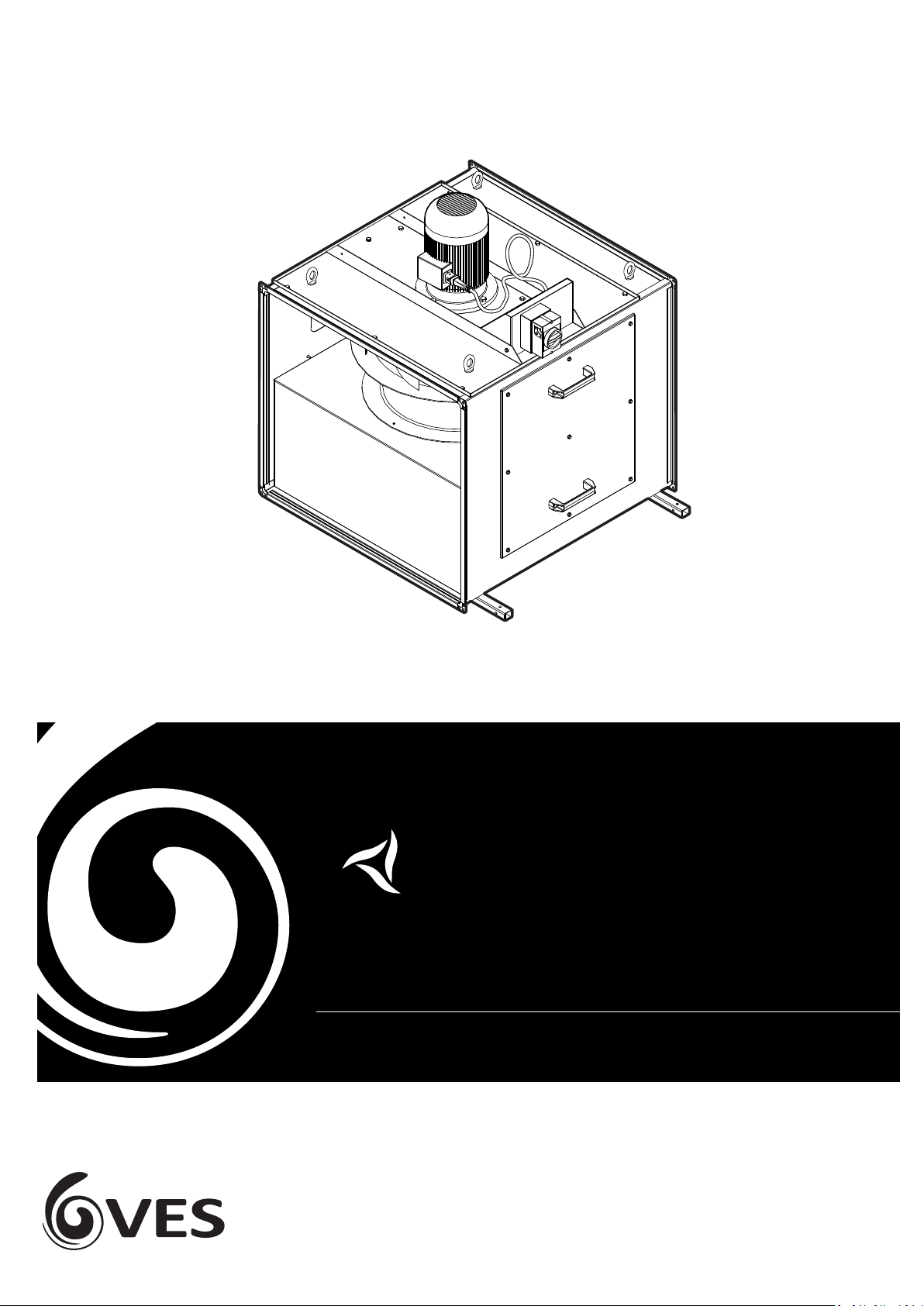
t-line Extract Units
Immediately upon receipt of goods, check for possible damage in transit. Also check to
ensure that any ancillary items are included. These will be supplied fied or taped to the
unit (in the case of small items). In the event of any damage having occurred or if any item
is found to be missing, it is essenal to inform VES Andover Ltd. within 3 working days of
delivery, quong the sale s order (SO) number, and the unit type as found on the unit
nameplate. Aer this period VES Andover Ltd. will be unable to accept any claim for
damaged or missing goods.
Receipt of Goods
When moving the unit, handle with care and in such a manner liming damage to the
casework. Parcular care must be taken when moving weatherproof units, any damage to
the external powder coat finish may reduce the ability to resist corrosion. Units are to be
rigged and lied using spreaders, taking into account the weight of the unit, liing gear
should be arranged so as not to bear on the casework.
Installaon
Safety for the enre system must be considered when installing the unit and it is the
responsibility of the installer to ensure that all of the equipment is installed in
compliance with the manufacturer’s recommendaons, with due r egard to the current
HEALTH AND SAFETY AT WORK ACT and conform to all relevant statutory regulaons.
Precauons should be in place so that in the unlikely event of component failure the risk of
personnel injury is reduced. For opmum unit performance, careful consideraon must be
paid to the locaon of the unit in relaon to the ductwork and associated items; i.e placing
the unit directly adjacent to a bend in the ductwork will impede airflow and reduce
performance.
Duct Connecons
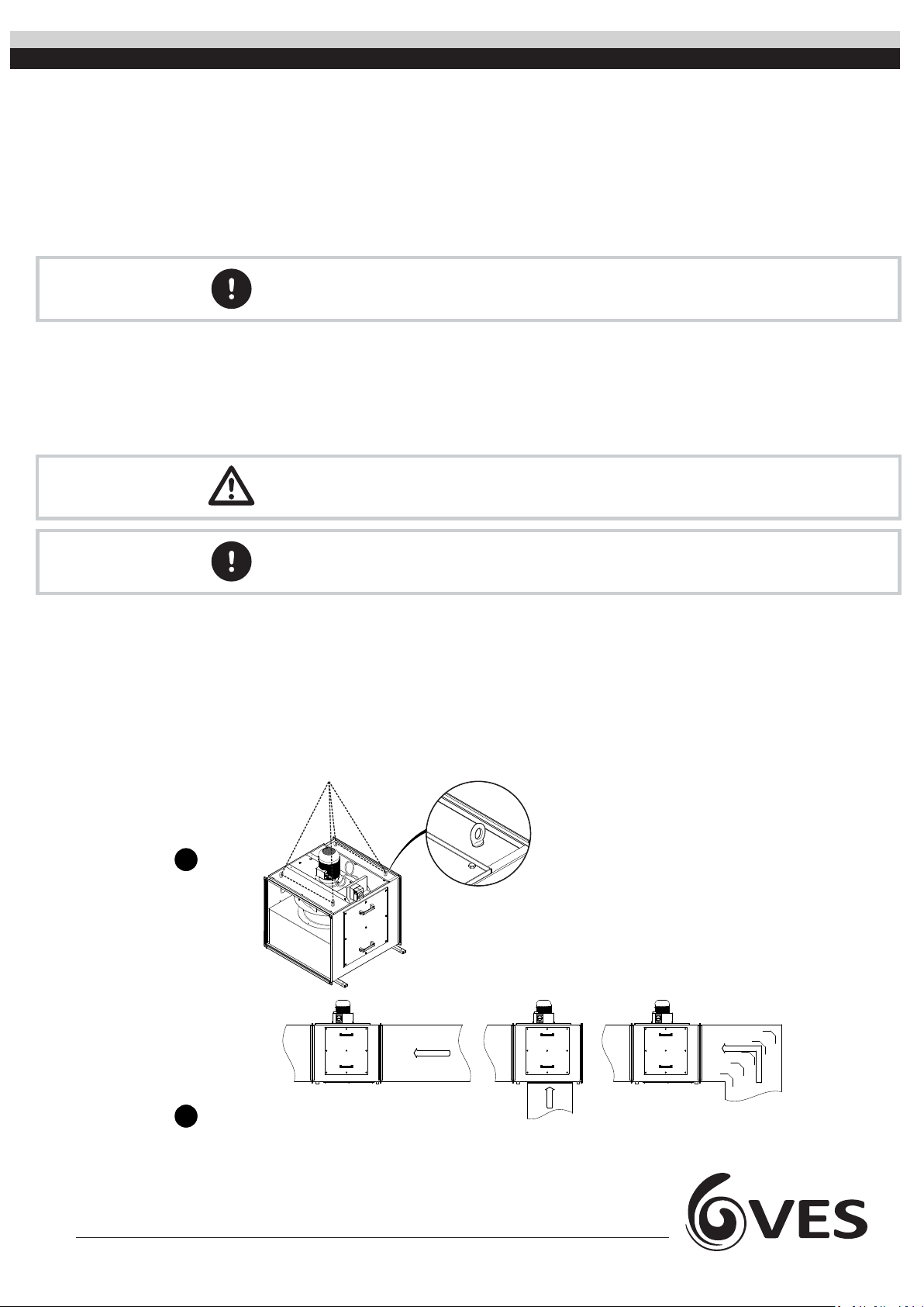
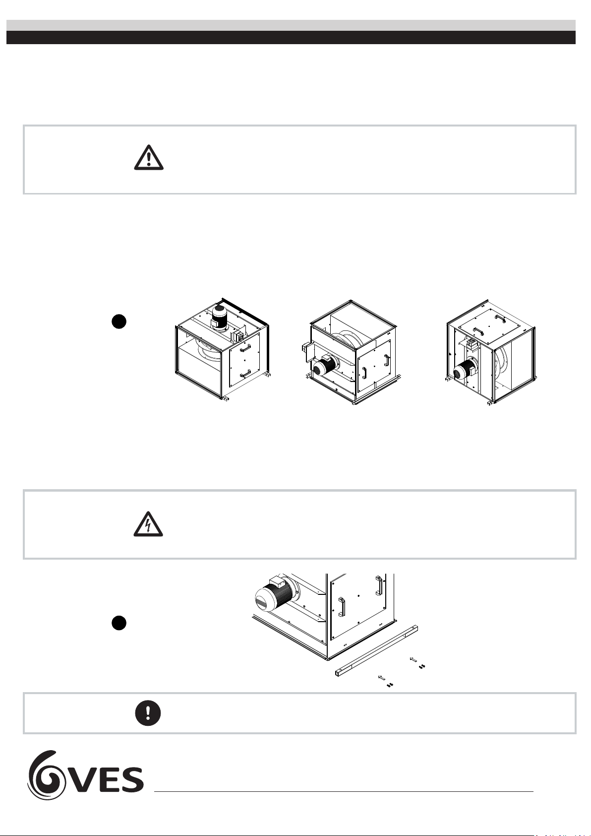
Liing and Connecng
to Duct
Cauon
3
Important The unit should NOT be lied by handles, lids, housings, sha, motor or drive.
Only experienced engineers should undertake this work.
Secure liing cable through the liing lugs.
Ensure fan plate is securely in place before
liing the unit.
It is recommended that the unit is lied
using the supplied liing lugs.
(For illustraon
purposes only)
3
4
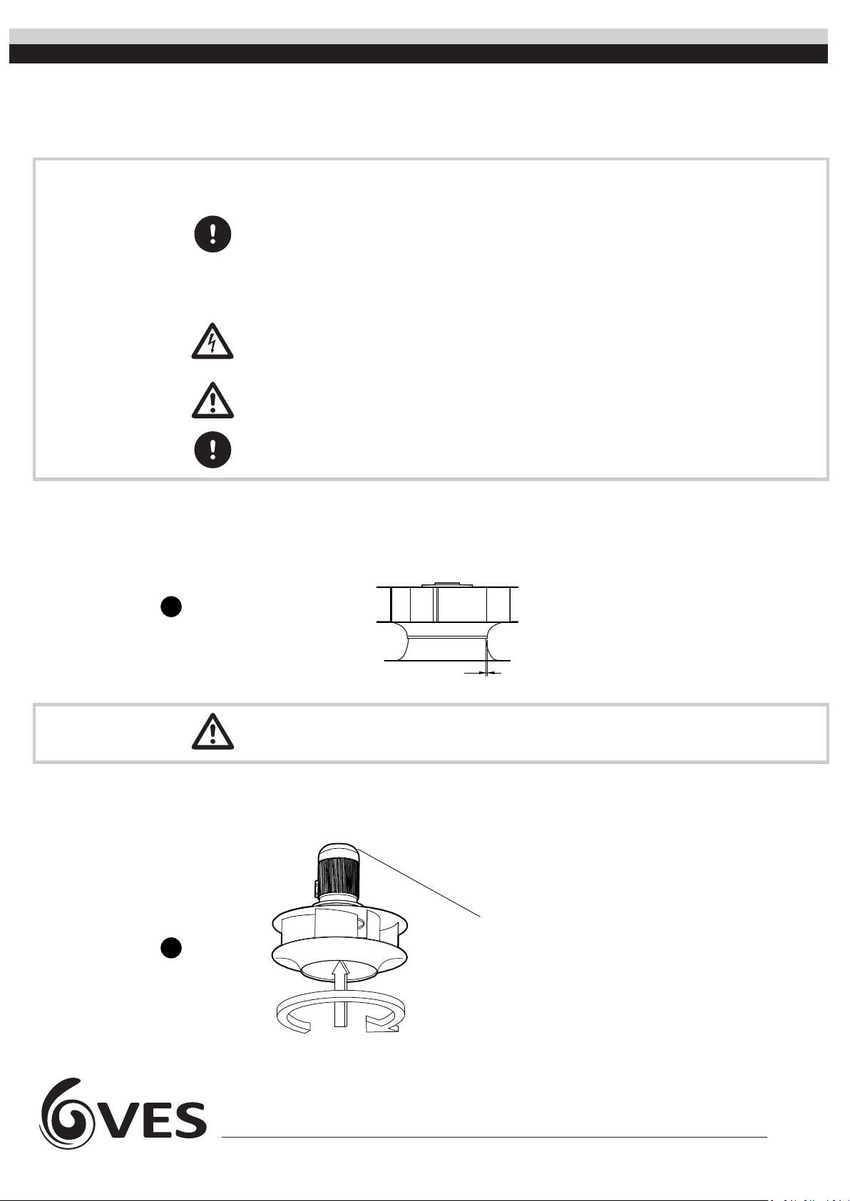
Recommended only with fied
turning vanes
RecommendedRecommended
Fig. 1
Fig. 2
Important An Inverter Speed controller is required for the operaon of this fan