VESA 80486 Deep Green User manual

11.
2.
3.
Please short pins 2-3 on jumper
JPl
before using this
system mainboard.
In GREEN CPU inactive mode, the system will stop the
DOS timer. To update the DOS timer, please use
Microsoft POWER.EXE to put the following line in your
config.sys
file:
DEVICE=POWER.EXE STD
Please check the Intel CPU type detected by the BIOS in
the start-up screen:
If the detected Intel CPU is a
DX4-S,
80486DX2-S,
80486DX-S
or
80486SX-S,
the CPU jumpers must be set for
a DX-SL CPU.
If the detected Intel CPU is a
80486DX,
80486DX2,
or
80486SX,
the CPU jumpers must be set for a
DX/DX2
CPU.
The information presented in this publication has been
carefully checked for reliability; however, no responsibility
is assumed for inaccuracies. Specifications are subject to change
without notice.
Trademarks
IBM, PC/AT, and OS/2 are trademarks of International
Business Machines Corporation.
AMD is a trademark of Advanced Micro Devices Inc.
AWARD is a registered trademark of Award Software Inc.
Microsoft is a registered trademark of
Microsoft
Corporation.

Contents
Chapter 1:Introduction
..................................................
1
Key Features.....................................................................
2
Unpacking the Mainboard
.................................................
3
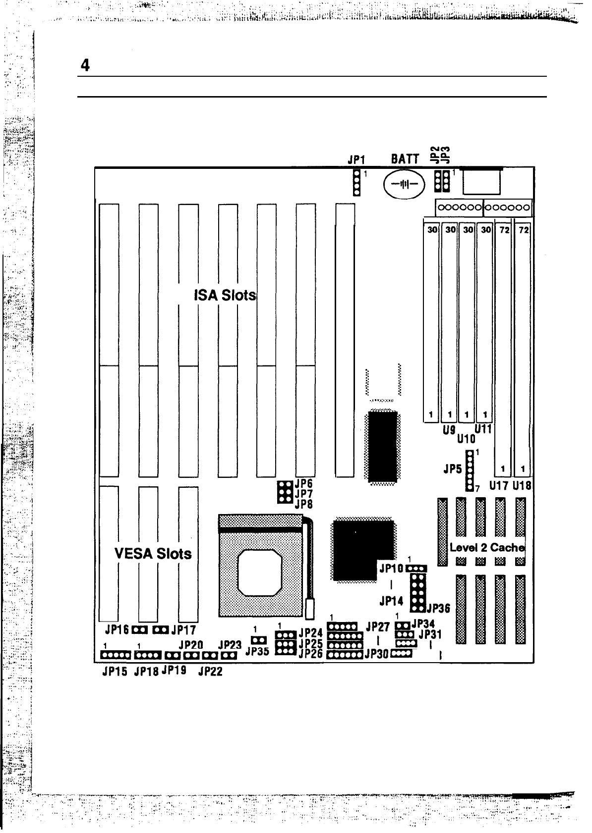
Mainboard Layout.............................................................
4
Chapter 2: Hardware Configuration.
...........................
5
Power Precautions
.............................................................
5
Jumper Switch Settings
......................................................
5
JP3
-
FlashROMVPPSupply
Selector......................
6
JP27-JP30,
JP32,
JP33-
CPU Type Jumpers
...................7
JP6-JP8
-
CPU Clock Setting
.....................................
7
JP31-
Intel
80486DX4
CPU Clock Multiplier Jumper
..
.8
JP34-
AMD
80486DX4
CPU Clock Multiplier Jumper . .
8
JP21-JP24,
JP35
-
CPU
Power
Selectors......................
.8
JP16
-
VESA Clock
Selector
.......................................
8
JP17
-
VESA Wait State...........................................
9
Memory Configuration.......................................................
9
Chapter 3: Mainboard Installation
.....
....................
10
What You Need
...............................................................
10
Power Supply Requirements
..............................................
11
Installing the Mainboard
.................................................12
Connecting
the Mainboard
................................................
13
Connectors
........................................................................
13
Jl
-
Keyboard Connector
...........................................
13
J9
-
Power Supply Connectors
....................................
14
.’
‘-
J18
-
Speaker Connector
............................................
14

25
.
.
.
.
.
.
.
.
l
.
*
.
.
l
:
.
.
.
.
.
.
.
.
.
.
.
.
.
.
.
.
.
*
.
’
.
.
*
:
.
.
*
.
.
.
.
.
.
.
3
;
g
:
c
.
i3
;
n
$5
ii7
8
s
td
3
v2
?a
Es
2
8
x
s
cil
aJ
I
x
IA
pz
2
.
.
.
.
.
.
.
.
.
.
.
.
:
.
.
.
.
.
.
.
.
.
.
.
.
.
.
.
.
.
.
.
.
.
.
.
.
.
8
z
2
5
w
a
3
x
3
t-(
I
m
E:
a
H
.
.
.
.
.
.
.
.
.
.
.
.
.
.
.
.
.
.
.
.
.
.
.
.
.
.
.
.
.
.
.
.
.
.
E
8
2
3
A
I!
.
$
cn
5
Is
i
e
h
(_(
.
.
.
.
.
.
.
.
.
.
.
.
.
.
.
.
.
.
.
.
.
.
.
.
.
.
.
.
.
.
.
.
.
.
.
.
5
8
2
s
A
3
‘d
3
m
2
5
v
z
cl
th
H
.
.
.
.
.
.
.
.
.
.
.
.
.
.
.
.
.
.
.
.
.
.
.
.
.
.
.
.
.
.
3
%
2
3
A
3
.
5
cn
2
!i
3
I
iTi
e
00
v-
.
.
.
.
.
.
.
.
.
.
.
.
.
.
.
.
.
.
.
.
.
.
.
.
.
.
.
.
.
.
.
.
.
.
.
.
.
.
.
.
.
.
.
.
s
,.$
8
6
A
3
E
92
2
6
Q,
z
ci?
El
:
:
:
:
:
:
:
:
:
:
:
:
:
:
:
:
:
:
:
:
:
:
:
.
i
&
2
CE
;3
E
4
E
i?
6
8
:
:
:
:
:
:
:
:
:
:
.
:
:
:
:
:
:
:
:
:
:
:
:
:
:
:
:
:
:
t
cz
8
z
1
3
4
qG
.
.
.
.
.
l
.
*
l
:
.
*
:
*
.
l
.
.
.
.
.
.
.
.
.
.
.
.
.
.
.
.
l
.
:
.
l
:
*
.
.
.
:
.
;
.
.
.
.
.
.
.
.
.
l
. l
l :
.
*
:
*
.
*
.
*
.
. .
. .
jd
.
.
.
2
iw
;
cn
2%
.
.
.
.
.
.
*
.
l
.
l
.
l
.
l
.
.
*
:
.
.
l
.
.
.
.
.
.
.
.
.
.
.
.
.
.
.
.
:
:
l
.
l
.
.
l
:
.
.
l
.
*
.
.
.
:
.
.
.
.
.
.
.
l
.
l
.
l
.
l
.
l
.
:
:
n
c‘!
.
.
.
.
.
.
.
.
.
.
.
.
.
.
.
.
SF3
.
.
0
r?
8
.
.
.
.
.
l
_
.
*
:
l .
*
.
-
.
.
;
.
.
.
.
.
.
.
.
.
.
.
.
.
*
.
’
.
l
*
:
l
.
l
.
.
l
.
.:
.
.
.
.
.
.
.
.
.
.
:
*
:
*
.
*
.
..
.
.
.
.
.
.
.
.
.
.
.
.
.
.
.
’
;2
G$
5
3
ILn
..
.
.
.
.
.
.
.
.
.
.
.
.
.
.
.
.
.
.
.
.
.
.
.
.
.
.
.
.
.
33
.
.
.
.
.
.
.
.
.
.
.
.
.
.
.
.
.
.
.
.
.
.
.
.
.
.
.
.
.
.
.
.
.
.
.
:
.
.
.
.
.
.
.
.
.
.
.
.
.
.
.
.
.
.
.
.
.
.
.
.
.
.
.
.
.
.
.
.
.
.
.
.
:
.
.
.
.
.
.
.
.
.
.
.
.
ic3
.
.
.
zi
s
‘%
CA
8s
E8
wE
a%
b-
SE
;
.
.
.
.
.
.
.
.
.
.
.
.
.
.
.
.
.
.
.
.
.
.
.
.
.
.
.
.
.
.
.
.
.
.
.
.
.
.
.
.
.
.
.
.
.
.
.
.
.
.
.
.
.
.
.
.
.
.
.
.
.
.
.
.
.
:
.
.
.
.
.
.
.
.
.
.
.
.
.
.
.
.
.
.
.
.
.
.
.
.
.
.
.
.
.
.
.
.
.
.
.
.
.
.
.
.
.
.
.
.
.
.
.
.
.
.
.
.
.
.
.
.
.
:
.
.
.
.
.
.
.
.
.
.
.
.
.
.
.
.
.
.
z
‘r!
.
.
.
.
.
.
.
.
.
.
.
.
.
.
.
.
:
.
.
.
.
.
.
.
.
.
.
.
.
:
.
.
.
.
:
.
.
.
.
.
.
.
:
.
.
.
.
:
.
.
.
.
.
.
.
.
.
.
:
.
.
.
.
:
.
.
.
.
.
.
.
.
.
.
.
.
.
.
.
.
.
.
.
.
.
.
.
.
.
.
.
.
.
.
.
.
.
.
.
.
.
.
.
:
.
.
:
.
.
.
:
.
.
.
.
.
.
.
.
.
.
.
.
.
.
.
.
.
.
.
.
.
.
%x3
.
.
.
.
.
.
:
.
.
.
.
.
.
.
.
.
:
.
.
.
.
.
.
.
.
.
.
.
.
.
.
.
.
.
.
.
.
.
:
.
.
.
.
.
.
.
.
:
.
.
.
.
.
.
.
:
.
.
.
.
si
2
s
.
.
.
.
.
.
.
.
.
.
.
:
.
.
.
.
.
.
.
.
.
.
.
.
.
.
.
.
:
.
.
.
.
.
.
.
.
:
.
.
.
.
.
.
.
:
:.
. :
.
.
.
:
:
.
.
.
.
:
.
.
:
.
.
.
.
:
.
.
.
.
.
:
.
.
.
.
.
.
.
. :
.
.
:
.
.
.
.
.
.
.
.
.
.
.
.
.
.
.
.
:
.
.


_ Chapter
1
.
Introduction
The 80486 Deep Green mainboard is a 32-bit high-performance
system board. This mainboard is not only compatible with
IBM AT systems, but it also provides power-saving features
that allow the user to program the timer.
You can configure the 80486 Deep Green mainboard for use with
many
486based
microprocessors, such as the following:
QIntel
P24T
a
Intel
P24D
m
Intel
80486DX4
(P24C)
a
Intel 80486DX2/DX/SX-SL
0
Intel
80486DX2
/
DX
/SX
a
CyrixCX486DX2/DX/S
a
AMD
AM486DX4/DX2/DX
c1
UMCU5
The 80486 Deep Green mainboard features on-board power
management that allows the user to assign system clock rates,
hard disk power saving and display power saving when
entering doze mode, suspend mode or inactive mode.

2
Chapter
Key Features
0
0
0
0
Advanced features of the 80486 Deep Green mainboard include:
Supports
CPUs
running at
25/33/40/50/66/75/80/100
MHz:
-
Intel
P24T
-
Intel
P24D
-
Intel
80486DX4
(P24C)
-
Intel
80486DX2
/
DX
/
SX
-
SL
-
Intel
80486DX2
/
DX
/SX
-
Cyrix
CX486DX2
/
DX
/
S
-
AMD
AM486DX4
/
DX2
/
DX
-
uMcu5
Ll
write back or write through cache
L2 write back policy for high performance
Flexible cache RAM size
64/128/256/512/1024
KB in two
banks or one bank with 16 bytes line size
DRAM auto-detection
/
banking
Four banks of DRAM with memory size to 64 MB using
combinations of
256K,
lM,
2M,
4M,
8M,
16M,
32M,
64M
SIMM
Provides green PC power management
Level 2 cache power saving
Supports four power management modes for SMM (System
Management Mode)
CPUs:
On, Standby, Inactive, Off.
Seven 16 bit I/O slots including three 32-bit VL-Bus master
slots
On-board CR2032 3.0 Volt lithium battery
237-pin ZIF socket
Provides flash ROM support
Fully supports Microsoft APM (advanced power
management)
Supports 3.3
/
4.0 Volts for low voltage CPU

Introduction
3
Unpacking
the
Mainboard
.
The mainboard comes packed in a sturdy cardboard shipping
carton. The carton contains:
0
The 80486 Mainboard
l
This User’s Guide
Note: Do not remove the mainboard from its original packing until
you are ready to install it.
The mainboard is easily damaged by static electricity.
Observe the following precautions while unpacking and
installing the mainboard.
1.
Touch an unpainted area of the system chassis before
handling the mainboard or any component. Doing so
discharges the static charge your body may have built.
2.
Remove the mainboard from its anti-static wrapping
and place it on a grounded surface, component side up.
3.
Inspect the mainboard for damage. Shipping may have
loosened integrated circuits from their sockets. If any
integrated circuit appears loose, press carefully to seat
it firmly in its socket.
Do not apply power if the mainboard appears damaged. If
there is damage to the board, or items are missing, contact your
dealer immediately.

Chapter
1.
Mainboard
Layout
.%~.f*...*...*..
:: ::
::
::
3
:: ::
::
::
::
-I
::
(
:: ::
:: $
3
i
:: $
?:
::
1
.
.
.
.
.
.
.
.
.
.
.
.
.
.
..I
.
..T
,.I.
.
.
.
.
.
.
.
2
3
.l
2:
.:
:. .$
.*
-:I
::;
x
::
::
2
::
::
;:
:!
.
..*.V.*.*...v
U8
“U,
6”’
JP5
Mom
JP30
=
JP33
JP15
JPl8Jt'ly
JPZZ
Figure
1-1.
Mainboard
Layout

-Chapter 2
Hardware Configuration
Before you install the 80486 mainboard into the system
chassis, you may find it convenient to first configure the
mainboard’s hardware. This chapter describes setting jumpers,
installing memory modules, and attaching components.
Power Precautions
Before you begin configuration, make sure you are working
with an unplugged mainboard. Many components are powered
by low-voltage current, but there still may be a dangerous
electric current coming from the leads and power supply. Take
the following precautions:
0
Turn off the power supply, and unplug the power cord
before you begin.
l
Unplug all cables that connect the mainboard to any
external devices.
Jumper Switch Settings
You can configure hardware options by setting jumper switches
on the mainboard. See Figure 1-l for jumper locations. Set a
jumper switch as follows:
0
Short a jumper by placing the plastic jumper cap over
two pins of the jumper.
0
Open
the pins of a jumper by removing the jumper cap.

6
Chapter 2
Note: When you open the jumper, attach the plastic jumper cap to
one
of
the pins so you don’t lose it.
For setting 3-pin jumpers, the symbols below are used:
l-2
Pins 1 and 2 are Shorted with a jumper cap.
2-3
Pins 2 and 3 are Shorted with a jumper cap.
For setting 2-pin jumpers, the following symbols are used:
ON
The jumper is Shorted (ON) when the jumper
cap is placed over the two pins of the jumper.
OFF
The
jumper is Open
(OFF)
when the jumper cap
is taken off of the jumper.
JP3
-
Flash ROM VPP Supply Selector
JP3 is the Flash ROM Program Voltage selector.
Description
5 volt
JP3
l-2
I
12 volt
I
2-3
I

Hardware Configuration
7
JP27-JP30,
JP32,
JP33-
CPU Type Jumpers
Set
jumpers
JP27-JP30,
JP32, and
JP33 so that the
recognizes the type of CPU installed. Set CPU type
Note:
A wrong setting may cause the system to hang up.
mainboard
as below.
1
Jumper
/
JP27
JP33
2-3
JP32
OFF
1-2
1-2
1-2
2-3
2-3
l-2, 3-4OFF
OFF
l-2 l-2
5-6
1-2, 3-4
l-2, 4-5
(
3-4, 5-6 l-2, 3-4
l-2
)
5-6 2-3 1-2, 3-4
OFF 2-3
1
CyrhM6I
2-3,4-5
l-2, 3-4, l-2, 3-4,
5-6 5-6
l-2, 3-4,
5-6
l-2, 3-4,
5-6 l-2 l-2, 3-4
(CyrixM7I
2-3 l-2, 3-4, 2-3, 4-5
5-6
2-3
(
l-2 3-4 2-32-3
2-3
I
I
OFF
1
OFF l-2 l-2, 3-4
t
AMD
1
OFF
L
JP6-JP8
-
CPU Clock Setting
CPU
Clock
JP6 JP7
JP8
25 MHz
OFF
OFF
ON
33 MHz
ON
ON ON
40 MHz
OFF ON ON
50
MHz
ON
OFF OFF

JP31-
Intel
80486DX4
CPU Clock Multiplier Jumper
Clock Multiplier
JP31
3x OFF
2.5 X
1-2
2x
2-3
JP34-
AMD
80486DX4
CPU Clock Multiplier Jumper
Clock Multiplier
JP34
3x
(
OFF .
2x
ON
JP21-JP24, JP35
-
CPU Power Selectors
CPUPower
Jp24
5 Volts
2-3
Jp=
J-P=
JP35
2-3
2-3
1
OFF
(
3.3 Volt
(
1-2
I
l-2
I
l-2
I ON
I
I
4 Volts
I
l-2-[
1-2
1
1-2
)
OFF
I
JP16
-
VESA Clock Selector
when the CPU clock is less than or equal to 33 MHz take the
jumper OFF of
JP16.
When the CPU clock is greater than 33 MHz
put a jumper ON
JP16.
I
Description
I
rp16
I
<=33MHz
OFF
>
33 MHz
ON
“-*_
.
.
.i;

Hardware Configuration
9
JP17
-VESA
Wait State
.
JP17 sets the VESA wait state.
Description
Jp16
OWS
OFF
1
ws
ON
i
Memory Configuration
The DRAM sub-system contains 4 banks. Four 30-pin SIMM
sockets
U8-U11
are bank 2; two 72-pin SIMM sockets U17 is
bank
1
and 3; Ul8 is bank 0 and 2.
You can not install 30-pin SIMM if you use 2-bank type DRAM
in
U18,
but you can install 30-pin SIMM if you use l-bank type
DRAM in
U18.
U8-U11
U18
U17
BANK
2
BANK 0,2 BANK 1,3
Installed l-bank type DRAM
2-bank type DRAM
or or
None
l-bank type DRAM
or
None
None
2-bank type DRAM 2-bank type DRAM
or
or
l-bank type DRAM l-bank type DRAM
or or
None None

Chapter 3
Mainboard Installation
_.
.
Once you have configured the 80486 Deep Green mainboard’s
hardware, you are ready to install the mainboard into the
system chassis This chapter describes what you need to
assemble an advanced computer system based on the 80486
mainboard.
What You Need
The following components and tools are the minimum required
to build a working computer system.
Components
The following components are recommended:
0
Case with standard chassis and hardware. The 80486
fits most AT compatible cases.
0
Standard AT power supply
0
8 ohm speaker
0
Floppy disk drive(s)
(36OKB,
1.2MB,
1.44MB
or
2.88MB)
0
Hard disk drive (optional)
0
Hard disk and floppy disk drive controller card
0
Flat
and ribbon cables to connect the disk drive controller
the disk drive(s)
.
--
*-.
a
_.
r-‘.

Mainboard Installation
11
lSerial /parallel interface card
0
AT-compatible keyboard
0
Video card and Display (monochrome, CGA, EGA, or
VGA)
Tools
Installing the 80486 mainboard requires the following tools:
0
l/4-inch
Nutdriver
0
3
/
16-inch
Nutdriver
_
You can also use a Phillips screwdriver with a 6-inch shaft
and a flat blade screwdriver instead of the nutdrivers.
Power Supply Requirements
You need a clean, steady power source to get the best
performance from your system. For reliable performance, make
sure your power supply provides a voltage range of 5.25 volts
maximum to 4.75 volts minimum. If your area has noisy power
transmission, use a line noise filter between the power source
and your computer.
You must make sure the power supply can supply the total
power required by all the devices in your system. Check the
power requirements of the floppy disk drives, hard disk
drives, and any additional boards that you will use. In a
system that includes a hard disk drive and installed adapter
cards, use a power supply of at least 180 watts.

‘1 2
Chapter 3
_.
.
Installing the Mainboard
Before you begin, check the location of the mounting holes in
the case and on the mainboard.
Caution: Static electricity can damage the mainboard.
Install the 80486 mainboard as follows:
1.
2.
3.
4.
5.
Review the section on static electricity precautions at
the beginning of this manual.
Place the case on an anti-static mat and remove the
cover. Remove the nylon stand-offs and screws for
mounting the mainboard.
Put the front of the case to your right and the rear to
your left. The mainboard occupies the section of the case
nearest you; the power supply goes on the far side.
Align the mounting holes on the case to the mounting
holes on the mainboard. Make sure you can access the
keyboard connector
(Jl
once the board is installed.
From the bottom of the mainboard, insert stand-offs into
the proper holes on the board, and attach the mounting
screws to the bottom of the case.
Note: Some cases do not use stand-o@ and mounting screws; in this
case you can fasten the mainboard into the case with regular
screws.
6.
Place the mainboard
securely with regular
into the case and fasten the board
screws.
1
,
*-*
.’
r-’

Main board Ins
talla
tion
13
Connecting
ttie
Mainboard
*
Once you have fastened the mainboard into the system case,
the next step is to connect the internal cables. The internal
cables are wire leads with plastic female connectors that
attach to the connectors. The mainboard connectors have
varying numbers of pins and are the points of contact between
the mainboard and other parts of the computer.
Note: Before making connections on the board, make sure that power
to the system is turned
ofi.
Connectors
/”
JI
-
Keyboard Connector
A standard five-pin female DIN keyboard connector is located
at the rear of the board
(Jl).
Plug the jack on the keyboard
cable into this connector.
Pin
Description
1
Keyboard Clock
2
Keyboard Data
3
ClWnd
4
Ground
5+5V
DC

14
Chapter 3
_.
.
J9
-
Power Supply Connectors
.
The power supply connector has two six-pin male header
connectors. Plug the dual connectors from the power directly
Pin
Descrhtion
12
+5v
DC
11
+5v DC
10
+5v
DC
9
-5v Ix
8
GKXITId
7
Ground
L
onto the board connectors.
JIS
-
Speaker Connector
Pin
Descritdion
6
5
4
3
2
1
Attach the system speaker to connector
Jl8.
Gmund
-12v DC
+12v DC
+5V
DC
Power Good
Pin Description
1
Data Out
2
Not Used
3
Ground
4
+5v

Mainboard Installation
15
Note
2:
JPI
-
External Battery
.
The 80486 mainboard has a non-rechargeable lithium battery
on-board; however, you can also attach an external battery to
connector JPl. Using an external battery helps you conserve the
on-board batterv.
Note 2:
To clear the
A’
pins 34 and
operation.
,
Description
Tp1
External Battery
1-4
Internal Battery
2-3
Clear CMOS
3-4
The factory default setting has a jumper cap on pins 3-4 to
avoid losing battery power during shipping. For an
installed internal battery, place a jumper cap on pins 2-3.
When you install an external battery, remove this jumper
cap.
CMOS configuration, place a jumper cap on
then place the cap back on pins 2-3 for normal
JP15-Keylock
& Power LED Connector
JPl5 is a keylock connector that enables and disables the
keyboard and the Power-LED on the case.
Pin
1
Description
LED power
Not Used
Keyboard Inhibiter
GnXlnd
’
j
:
.!
;/
i
!
,
:
i
!
/
I
.
!
’
!
i
/i

16
Chpter
3
JP19
-
Turbo LED Connector
JPlks
usually connecteh to a Turbo LED on front of the system
case.
If
the system board select is in Turbo mode, the indicator
lights during high-speed operation.
_.
.
JPZO
-
Reset Switch Connector
Attach the Reset switch cable to this connector. The Reset
switch restarts the system.
Pin Description
t
,
1
+Anode
2
-Cathode
Setting
Short
ape
n
Description
Reset
1
Not Reset
1
Table of contents
Other VESA Motherboard manuals