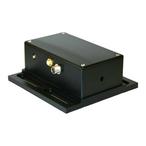
Vescent Photonics D2 Series User manual

Quick Setup
Guide
Vescent Photonics, Inc.
www.vescentphotonics.com
4865 E. 41st Ave
Denver, CO 80216
Phone (303)-296-6766
Fax (303)-296-6783

General Warnings and Cautions
The following general warnings and cautions are applicable to this instrument.
WARNING
This instrument is intended for use by qualified personnel who
recognize shock hazards or laser hazards and are familiar with
safety precautions required to avoid possible injury. Read the
instruction manual thoroughly before using to become familiar
with the instrument’s operations and capabilities.
CAUTION
There are no serviceable parts inside the instrument. Work
performed by persons not authorized by escent Photonics may
void the warranty.
CAUTION
Although ESD protection is designed into the instrument,
operation in a static-fee work area is recommended.
WARNING
To avoid electrical shock hazard, connect the instrument to
properly earth-grounded, 3-prong receptacles only. Failure to
observe this precaution can result in severe injury or death.
WARNING
Do not clean outside surfaces of any escent Photonics products
with solvents such as acetone. Front panels on electronics
modules may be cleaned with a mild soap and water solution.
Do not clean optics modules.

Limited Warranty
escent Photonics warrants this product to be free from defects in materials and workmanship for a period of one year
from the date of shipment. If this product proves defective during the applicable warranty period, escent Photonics, at
its option, either will repair the defective product without charge or will provide a replacement in exchange for the
defective product. The customer must notify escent of the defective product within the warranty period and prior to
product return. The customer will be responsible for packaging and shipping the defective product back to escent
Photonics, with shipping charges prepaid.
escent Photonics shall not be obligated to furnish service under this warranty from damage caused by service or repair
attempts made without authorization by escent Photonics; from damage caused by operation of equipment outside of
its specified range as stated in either the product specification or operators manual; from damage due to improper
connection to other equipment or power supplies.
This warranty is in lieu of all other warranties including any implied warranty concerning the suitability or fitness of
the product for a particular use. escent Photonics shall only be liable for cost of repairs or replacement of the
defective product within the warranty period. escent Photonics shall not be liable for any damages to persons or
property resulting from the use of the product or caused by the defect or failure of this product. escent Photonics'
liability is expressly limited to the warranty set out above. By accepting delivery of this product, the purchaser
expressly agrees to the terms of this limited warranty.
escent Photonics
Printed May 19, 2008


Vescent Photonics D2 Series Product Manual
1. Quick Setup Instructions
1.1. Electronic Modules Initial Setup
Place the three electronics modules (System Power,
Laser Controller and Laser Servo) in a row as shown on
the right (order is not important).
On the back of the modules, attach the two power
bridges across adjacent modules. See picture below.
On the Laser Controller, in the bottom left corner,
make sure that the LASER switch is in the
OFF/RESET (down) position.
Make sure the power switch on the System Power
module is in the OFF (down) position. Plug power
cable into back of System Power module.
1.2. Optic Modules Initial Setup
Place the DBR Module on an optics table
and bolt to table with 4 1/4-20 screws.
Align the Spectroscopy Module to the DBR
Module, but place Spectroscopy Module at
least 3” away from the DBR Module.
To help with optical alignment, loosen the
four screws that hold each module and gently
register the modules by pushing against the
screws in the same direction. (This is how
they were aligned at escent.)
1.3. Cabling & Power
Locate the 6ft SMA cable circular connector cable assembly. Plug the SMA connector into the LASER
CURRENT OUTPUT plug and LASER TEMP OUTPUT on the Laser Controller. Make sure that the
nearby Laser switch is in the OFF/RESET position (down). While grounded, remove the SMA terminator
connected to the DBR Laser. Connect the other end of the SMA cable and circular connector to the DBR
module.
5

Vescent Photonics D2 Series Product Manual
Find the 6ft SMA / BNC cable and circular
connector cable assembly. Plug the BNC
end into the ERROR INPUT on the Laser
Servo. Plug the SMA end into the
Spectroscopy Module. Connect the circular
connectors.
Take one short (~1ft) BNC cable and
connect it from the CURRENT SER O
INTPUT on the Laser Controller to the
CURRENT SER O OUTPUT on the Laser
Servo.
For Peak-Lock Only: Connect one short
(~1ft) BNC from the RF INPUT on the
Laser Controller to the RF OUTPUT on the
Laser Servo.
Optional: For greater long-term stability,
connect one short (~1ft) BNC from the
TEMP SER O INPUT on the Laser
Controller to the TEMP SER O OUTPUT
on the Laser Servo. This shifts long term
drift to the temperature servo.
Flip the switch on the System Power Module to the ON position. Three LED's (+5 , +15 , -15 ) on the
System Power modules should glow blue.
Both the Laser Controller module and the Laser Servo module should have a blue LED glowing next to
the label POWER. If not, check that the power bridges are properly connected on the back.
1.4. Laser Controller
Flip the TEMP LOCK switch on the Laser Controller into the SER O position. A green light next to T2
should turn on in ~30 seconds. In ~3 minutes, the T1 green light should also turn on. You may use the
laser before stage 1 temperature (T1) is fully stabilized. The LEDs turn red if the temperature servo
senses an error condition, or if the laser is not between 0 and 50°C. They will show red until LASER
TEMP OUTPUT is connected (open condition), and when the TEMP LOCK is in the STANDBY
position.
Rotate the display selector knob in the upper right corner of the Laser Controller until the “Ilim” indicator
is lit. Make sure the current limit value shown is below 180 mA.
The Laser Controller has two safety interlocks. If either interlock is tripped, the laser will turn off and
stay off until the interlock condition has been fixed AND the Laser switch has been moved from
“off/reset” position to the “on” position. To turn the laser on for the first time follow the subsequent
procedure:
1. Place the front panel Laser switch in the “off/reset” position.
2. Place the included terminator on to the back-panel “remote interlock” BNC.
6

Vescent Photonics D2 Series Product Manual
3. Take the key that was taped to back of the Laser Controller and place it in the back-panel Laser
Enable keyhole and rotate the key 90 degrees (the key should be horizontal).
4. Now that both interlocks are enabled, flip the Laser switch into the “on” position. The green
“Laser On” light should turn on and 5 seconds later the laser should turn on.
Rotate the display selector knob in the upper right corner of the Laser Controller until the LED
underneath the label “I” is lit. Adjust the COURSE CURRENT to the value given in the accompanying
paperwork to place the laser on the D2 hyperfine transitions.
1.5. Laser Servo
On the Laser Servo, place the LASER STATE switch into the RAMP position. Turn the RAMP AMP
knob to max (clockwise). Connect a BNC cable from RAMP TTL on the back of the Laser Servo to the
trigger input on your oscilloscope. Set trigger to positive slope.
You should see the rubidium hyperfine transitions on
the ERROR IN monitor. Adjust the laser current to
move the transitions to the left and right. You should
see something similar to the figure on the right.
There are four Doppler broadened peaks. (The
picture shows three of them.)
If you don’t see the hyperfine transitions don’t panic.
More than likely the pickoff beams in the
spectroscopy module need adjustment. Make sure all
four screws are holding down the DBR and
spectroscopy modules. Loosen the spectroscopy
module screws and try making small adjustments
while looking at the ERROR IN signal. You can also
try scanning the laser current.
If you still cannot get spectroscopy, remove the screws to the top of the spectroscopy module and adjust
the course steering mirror (see below).
7

Vescent Photonics D2 Series Product Manual
If you still cannot get the right signal strength, see the full instructions on aligning the spectroscopy
module in the Spectroscopy Manual.
1.6. Locking the laser
1. .1. Setting up the oscilloscope for locking.
Connect a BNC cable from RAMP TTL on the back of the Laser Servo to the trigger input on
your oscilloscope. Set trigger to positive slope. Connect a BNC cable from the DC ERROR to
your oscilloscope. Connect a BNC cable from ERROR INPUT to your oscilloscope.
Adjust the Coarse and Fine Current control to place a transition peak at the center of the
oscilloscope screen. Reduce the ramp amplitude so you can clearly see the hyperfine transitions
(adjust fine current as necessary). As you lower the ramp amplitude and bring it back, you will
see the spectroscopy on the oscilloscope expand and contract about a single point on the
oscilloscope. The point should be near the center of the oscilloscope. Adjust the horizontal
position on the oscilloscope to put this point in the exact middle of the oscilloscope screen. If you
move the spectroscopy so that a hyperfine peak is centered on the oscilloscope, it will be easier to
see exactly where this point is. Now as you change the ramp amplitude, the value of the trace at
the center of the oscilloscope should not change. Adjust the horizontal position again if
necessary.
1. .2. Side Lock
Note: The laser locks to the point where DC ERROR crosses zero voltage with a positive slope
and when the oscilloscope is triggering to the RAMP TTL with positive slope.
Adjust the laser current and ramp amplitude so you can clearly see the transition that you want to
side lock to. Do not ramp too far. The desired transition should occupy most of the screen. You
might see that while near a transition the value of DC ERROR moves up and down slightly as the
ramp value is changed. Lower the ramp until this effect is gone.
8

Vescent Photonics D2 Series Product Manual
Optional: For long term frequency stability on side lock, monitor ERROR IN on the oscilloscope,
open up the top of the Spectroscopy Module, and adjust the trimpot such that your desired lock
point crosses 0 on the oscilloscope.
Flip the LOCK MODE switch into the
SIDE LOCK position. The laser will lock
to a positive (upward) slope at the zero
crossing point. If the spot you want to lock
to has a negative slope, flip the GAIN
SIGN switch on the Laser Servo to make
the slope positive. The figure shows the
lockpoint on the DC ERROR signal.
(Note: the GAIN SIGN switch flips the
entire spectrum upsidedown.) Adjust the
DC Offset with the pot tweaker until the
desired lock point is at zero volts.
Adjust the COURSE gain pot to roughly
the number of turns transition you are
locking, shown in the accompanying
paperwork shipped with your laser system. (Turn to left till it clicks, then turn to the right the
specified number of turns.)
Center the spectroscopy such that the lock point is exactly in the center of the oscilloscope. Flip
the lock switch on the right from RAMP to LOCK. The DC error signal should now be reading
0 with visible noise.
Adjust the COURSE and FINE GAIN knob to minimize the noise in the DC ERROR. Too high a
gain usually kicks the laser out of lock or gives rise to sustained oscillations.
Look at the LD OUT monitor. If the value is less than about 50m then the laser successfully
locked to the desired transition. If it is greater then 50m the servo jumped to another lock point
or is railed.
If the laser did not properly lock see the Laser Lock trouble-shooting section () on page .
1. .3. Peak Lock
Note: The laser locks to the point where the DC ERROR crosses zero voltage with a positive
slope and when the oscilloscope is triggering to the RAMP TTL with positive slope.
Adjust the laser current and ramp amplitude so you can clearly see the transition that you want to
lock to.
If not connected, connect one of the short (~1ft) BNC's from RF OUTPUT on the Laser Servo to
the RF INPUT on the Laser Controller. This is the RF dither signal.
Monitor DC ERROR. Flip the LOCK MODE switch to the PEAK position. You should see a
signal that is the derivative of the spectroscopy signal. It may have a large DC offset that you will
have to adjust with the DC Offset trimpot.
Note: The PHASE and DITHER AMP adjustments are factory set. You do not need to adjust
these values.
9

Vescent Photonics D2 Series Product Manual
The laser will lock to where the error
signal crosses zero voltage with a
positive slope. If your desired lock
point has a negative slope, flip the
GAIN SIGN switch on the Laser
Servo to invert the signal and make
the slope positive.
The figure shows an oscilloscope
trace of DC ERROR (blue) and
ERROR IN (yellow) for the 87Rb
F=2→ F'=2, 3 hyperfine crossover
transition. Using the DC OFFSET,
center the DC ERROR signal
vertically about zero to insure that
the lock point is at the center of the
peak.
Adjust the COURSE gain pot to
roughly the number of turns transition
you are locking, shown in the accompanying paperwork shipped with your laser system. (Turn to
left till it clicks, then turn to the right the specified number of turns.)
Adjust the laser current such that the center of the desired peak is exactly in the center of the
oscilloscope. Switch LASER STATE from RAMP to LOCK. The ERROR IN signal should be
held constant at the height of the desired peak and DC ERROR should be at zero volts with
visible noise. If the ERROR IN value jumped when you clicked LOCK, then the laser jumped to
the wrong transition or the servo is railed.
Adjust the COURSE and FINE GAIN knob to minimize the noise in the DC ERROR. Too high a
gain usually kicks the laser out of lock or gives rise to sustained oscillations.
If the laser did not properly lock see the Laser Lock trouble-shooting section () on page .
10
Other manuals for D2 Series
2
Table of contents
Other Vescent Photonics Measuring Instrument manuals