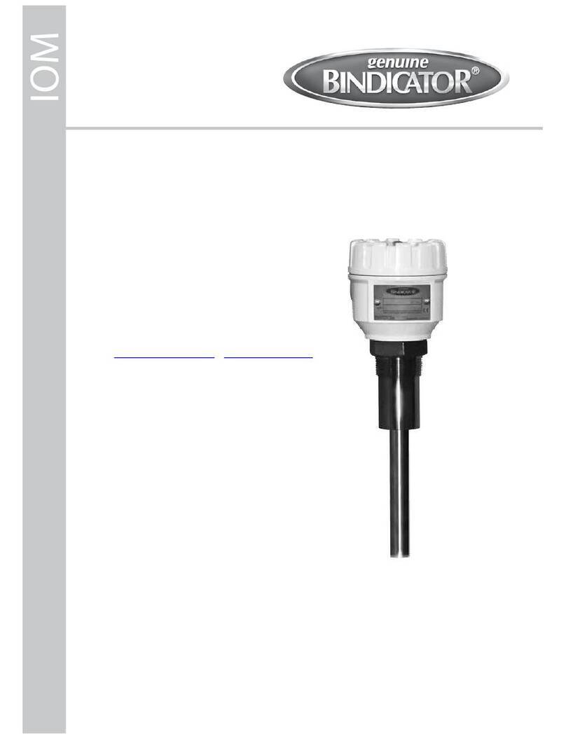
Bindicator MP Series User manual

MP Series Radar Transmitter
Installation & Operation Manual
IOM
MPR180213 Rev. B
Order from: C A Briggs Company - 632 Davisville Road - Willow Grove, PA 19090


MP Series Radar Transmitter
Installation & Operation Manual
CONTENTS
I. HANDLING AND STORAGE..................................................................................................................... 1
Inspection and Handling
Disposal and Recycling
Storage
II. GENERAL SAFETY................................................................................................................................... 2
Authorized Personnel
Use
Misuse
III. PRODUCT DESCRIPTION ....................................................................................................................... 3
Function
Technical Specications
IV. MECHANICAL INSTALLATION................................................................................................................. 4
Guidelines
Mounting Considerations
V. ELECTRICAL INSTALLATION .................................................................................................................. 7
General Safety
Disconnect Requirements For Permanently Installed Equipment
Wiring
VI. SET UP ............................................................................................................................................... 9
LCD Adjustment Unit
Tank Parameters Reference
Setting Parameters
Measurement Span
Dampening
Current Output
Echo Learning of False Echo
Reset
Current Output Test
Full Menu Structure
VII. MAINTENANCE ...................................................................................................................................... 19
Every 6 months:
Every 12 months:
VIII.TROUBLESHOOTING ............................................................................................................................ 20

SAFETY SYMBOLS
WARNING:
IDENTIFIES CONDITIONS OR PROCEDURES, WHICH IF NOT FOLLOWED, COULD
RESULT IN SERIOUS INJURY. RISK OF ELECTRICAL SHOCK.
CAUTION:
IDENTIFIES CONDITIONS OR PROCEDURES, WHICH IF NOT FOLLOWED, COULD
RESULT IN SERIOUS DAMAGE OR FAILURE OF THE EQUIPMENT.

1
www.bindicator.com
MPR180213 Rev. B
MP Series Radar Transmitter
Installation & Operation Manual
I. HANDLING AND STORAGE
SAVE THESE INSTRUCTIONS
INSpECTION ANd HANdlINg
Do not dispose of the carton or packing materials.
Each package should be inspected upon receipt for damage that may have occurred due to mishandling during
shipping. If the unit is received damaged, notify the carrier or the factory for instructions. Failure to do so may
void your warranty. If you have any problems or questions, consult Customer Support at 800-778-9242.
dISpOSAl ANd RECyClINg
This product can be recycled by specialized companies and must not be disposed of in a municipal collection
site. If you do not have the means to dispose of properly, please contact for return and disposal instructions or
options.
STORAgE
If the device is not scheduled for immediate installation following delivery, the following steps should be
observed:
1. Following inspection, repackage the unit into its original packaging.
2. Select a clean dry site, free of vibration, shock and impact hazards.
3. If storage will be extended longer than 30 days, the unit must be stored at temperatures between
32º and 158º F (0º to 70° C) in non-condensing atmosphere with humidity less than 85%.
CAUTION: dO NOT STORE A NON-pOWEREd UNIT OUTdOORS FOR A pROlONgEd pERIOd.

2MPR180213 Rev. B
www.bindicator.com
II. GENERAL SAFETY
AUTHORIzEd pERSONNEl
All instructions described in the document must be performed by authorized and qualied service personnel
only. Before installing the unit, please read these instructions and familiarize yourself with the requirements and
functions of the device. The required personal protective equipment must always be worn when servicing this
device.
USE
The device is solely intended for use as described in this manual. Reliable operation is ensured only if the
instrument is used according to the specications described in this document. For safety and warranty reasons,
use of accessory equipment not recommended by the manufacturer or modication of this device is explicitly
forbidden. All servicing of this equipment must be performed by qualied service personnel only. This device
should be mounted in locations where it will not be subject to tampering by unauthorized personnel.
MISUSE
Improper use or installation of this device may cause the following:
• Personal injury or harm
• Application specic hazards such as vessel overll
• Damage to the device or system
If any questions or problems arise during installation of this equipment, please contact Customer Support at
800-778-9242.

3
www.bindicator.com
MPR180213 Rev. B
III. PRODUCT DESCRIPTION
FUNCTION
The MP Series meter measures the level of bulk solids in the storage vessels without physical contact to the
The level meter transmits microwaves at constant intervals and receives echoes (reection of transmitted
waves) from the surface of the material under measurement. The time difference between the transmission and
reception of the microwave is processed by microcomputer to accurately determine the level of stored materials.
TECHNICAl SpECIFICATIONS
FUNCTIONAL
Antenna Horn
Power Supply 20 to 32 VDC
Power consumption Max. 704 mW
Mounting Swivel Flange
Dead Zone 11.8 in (30 cm) below the antenna
Max Measurable Distance 230 ft (70 m)
Transmitting frequency 26 GHz
Transmitting cycle Every 83 ms
Bean angle (-3 dB) Approx. 8º degrees
Resolution 1 mm
Allowable Fluctuation Rate 10 cm/s
PERFORMANCE
Accuracy ±1.2 in. or 0.04% of span, whichever is greater
Ambient Temp Housing: -40º to 140º F (-40 to + 60º C);
With LCD: -4º to 140º F (-20 to + 60º C).
Note: 1 hour warm-up operation required at -40º F (-40º C)
Antenna: -40º to 302º F (-40º to 150º C)
Pressure Horn/Transducer (Max): 145 PSI (1 MPa)
Swivel Mount Leakage (Max): 1.5 PSI (10k Pa)
Output signal 4 to 20mA x 1 (Resistive load Max. 499Ω), HART
Integral time 0-999s
PHYSICAL
Material Housing: Aluminum
Antenna: 316 Stainless Steel
Protection Housing: IP66 (Housing cover and lead outlet must be closed)
Antenna: IP67
Conduit Entry 1 - G1/2
Mass Approx. 13 lb (6.0 kg)

4MPR180213 Rev. B
www.bindicator.com
IV. MECHANICAL INSTALLATION
WARNINg: REMOVE pOWER FROM THE UNIT BEFORE INSTAllINg, REMOVINg, OR MAKINg
AdJUSTMENTS.
gUIdElINES
• The measurement range and accuracy are guaranteed only when the antenna is pointed at an angle
perpendicular to the material surface, and there is no presence of airborne dust, vapor, and agitated
foam. If these conditions are not satised, the measurement range and accuracy may differ according to
the measurement conditions.
• Ensure that freezing and/or condensing will not occur inside the electronic unit.
• If the cable gland is not tightened or loosens, water may enter and damage the equipment. When the
equipment operates in the presence of process gases and/or uids (especially corrosive gases those
materials may penetrate through the resin of the cone antenna and damage the equipment.
• Cable size: AWG 22 to 16 in (0.3 mm2to 1.25 mm2)
• If the material could enter the dead zone, a stand pipe can be used to ensure that the material surface
cannot reach the dead zone of the level meter.
• Mounting ange will mount to 150# ANSI type.
• Recommended height of stand pipe: the end of the horn antenna must be protruded a minimum of
0.4 in. (10 mm) from the stand pipe or the unit will not function properly. Avoid too long of a stand pipe to
prevent malfunction of the instrument.
• Set the value of 100% (20 mA) level so that the dead zone is included. Setting the 100% (20 mA) level
within the blind sector will cause a malfunction of the instrument.

5
www.bindicator.com
MPR180213 Rev. B
• Do not install the sensor close to the material ll pipe.
• Do not install any interfering instruments within the beam angle because reections from beams, pipes,
and other supports within the tank will cause false echoes.
• The sensor may need to be re-aimed if false echo mapping does not work.
• Install protection such as a simple roof above the level meter to avoid exposure to direct sunlight.
INSTAllATION
1. Determine where the unit will be installed.
2. Orient the unit so that the index mark is facing toward the center of the vessel.
3. Attach the unit to the vessel using the mounting plate or process tting.
4. For the swivel ange only, direct the unit into the vessel. Unit should be aimed
toward the center/gate of the vessel. Tighten bolts to the ange.
AIR pURgE
All units come standard with an air purge line, and should be used to keep the inside
of the antenna clean. The air purge tting size is G1/8. Please consult the factory for
installation guidelines.
Index Mark

6MPR180213 Rev. B
www.bindicator.com
V. ELECTRICAL INSTALLATION
WARNINg: REMOVE pOWER FROM THE UNIT BEFORE INSTAllINg, REMOVINg, OR MAKINg
AdJUSTMENTS
gENERAl SAFETy
When using electrical equipment, you should always follow basic safety precautions, including the following:
• The installation and wiring of this product must comply with all national, federal, state, municipal, and
local codes that apply.
• Properly ground the enclosure to an adequate earth ground.
•
Do not modify any factory wiring. Connections should only be made to the terminals described in this section.
• All connections to the unit must use conductors with an insulation rating of 300 V minimum, rated for
212º F (105º C), a minimum ammability rating of VW-1, and be of appropriate gauge for the voltage and
current required (see specications).
• Do not allow moisture to enter the electronics enclosure. Conduit should slope downward from the unit
housing. Install drip loops and seal conduit with silicone rubber product.
dISCONNECT REqUIREMENTS FOR pERMANENTly INSTAllEd EqUIpMENT
A dedicated disconnecting device (circuit breaker) must be provided for the proper installation of the unit. If
independent circuits are used for power input and main relay outputs, individual disconnects are required.
Disconnects must meet the following requirements:
• Located in close proximity to the device
• Easily accessible to the operator
• Appropriately marked as the disconnect for the device and associated circuit
• Sized appropriately to the requirements of the protected circuit (see specications)
WARNINg: dO WIRINg WHEN THE INSTRUMENT IS pOWEREd OFF. AVOId SHORT CIRCUIT ANd
REVERSE pOlARITy.
CAUTION: THE UNIT MUST BE SUpplIEd WITH A dC pOWER SUpply.

7
www.bindicator.com
MPR180213 Rev. B
WIRINg
1. Unscrew the cover. (rotate counterclockwise)
2. LCD unit is attached, remove it. (Rotate counterclockwise or to OPEN)
3. Open the wire entry of terminal block by pushing on the actuating lever with a at screwdriver
4. Insert wires as shown on the panel (positive (+) to terminal entry No. 1 and negative (-) to terminal No. 2)
5. Release actuating lever of the terminal
6. Connect the ground wire to internal earth ground terminal (D-Class grounding).
7. Attach the LCD unit if it had been installed
8. Screw the cover on tightly
9. Connect ground screw (D-Class grounding) between conduit entry to tank or any other earth ground.
Do not touch the LCD Adjustment Unit connection
terminal while instrument is powered on.
The LCD Adjustment
Unit removed
CAUTION: dO NOT CONNECT CABlE SHIEld WIRE ON dEVICE RECEIVINg 4-20mA SIgNAl.
Customer Supplied
(D-class grounding) M4
– + + –
Power Supply
24 VDC
Display/
Input

8MPR180213 Rev. B
www.bindicator.com
VI. SET UP
lCd AdJUSTMENT UNIT
1 32 4 5
NO. KEY FUNCTION
1 Esc • Interrupt entry (cancel)
• Returns to previous screen
2 + • Moves cursor
• Change value
• Change Y axis (re ection) of waveform
3→• Moves cursor to the left
• Change X-axis (distance) of waveform
4 Ent • Enters to menu
• Accepts value
• Shifts to next screen
5 Display Displays parameters and waveforms
TANK pARAMETERS REFERENCE
SETTINg pARAMETERS
It is recommended that the following characteristics are determined before programming. The chart below can
be used as reference, add more columns as necessary.
Sensor Address
Sensor Name
Units
(Check
one per
sensor)
Distance
Feet
Meters
Type Parameters
Tank Height
Full Distance
Empty Distance

9
www.bindicator.com
MPR180213 Rev. B
MEASUREMENT SpAN
Sets measurement span corresponding to the process level of 100% and 0%. Distance from level meter
measuring reference point to material surface. Percent is equal to the amount of current at each level. 100%
cannot be zero; must be set to least 11.8 in. (30 cm).

10 MPR180213 Rev. B
www.bindicator.com
dAMpENINg
Set the duration for the damping lter. The damping lter will smooth the response of a sudden change in the
level. The time can be set between 0 and 999 seconds. Keep in mind that the update time of the display and
output will be longer, but the sensor will react to changes with a delay.

11
www.bindicator.com
MPR180213 Rev. B
CURRENT OUTpUT
Selects the 4-20 mA current output mode corresponding to the process level 0-100% and alarm current value.

12 MPR180213 Rev. B
www.bindicator.com
FAlSE ECHO lEARNINg
Sets mask to unwanted reections (false echoes or noise echoes) being received from obstructions within a
tank. When the material level is low, measure the exact distance inside the vessel to the material. Set the echo
learning distance, 3 ft (1 m) less than the measured distance.
Tank should be empty when setting up the echo learning.

13
www.bindicator.com
MPR180213 Rev. B

14 MPR180213 Rev. B
www.bindicator.com
RESET
There are two reset options. Use “Measuring reset” to restart measurement without affecting parameters. Use
“Parameter reset” to reset parameters to the default settings.
NOTE: Parameter Reset
• Parameter reset returns various parameters to instrument default. Please take note of current settings
before execute parameter reset.
• It is possible to clear echo learning range and strength by using the PC software, please call factory for
assistance.
• There are two reset types described above, but there is menu item “Factory reset” might be displayed.
This reset type used at factory setting and user can not apply this reset.

15
www.bindicator.com
MPR180213 Rev. B
CURRENT OUTpUT TEST
Allows you to select a simulation value in order to test the functioning of the current output.
NOTE: When you are ready to end the simulation, click on ‘Esc’ to return the instrument to the actual level
measurement.

16 MPR180213 Rev. B
www.bindicator.com
FUll MENU STRUCTURE
All values shown are defaults
Table of contents
Other Bindicator Measuring Instrument manuals
Bindicator
Bindicator Pulse Point LP-500ST User manual

Bindicator
Bindicator PRD1000 User manual

Bindicator
Bindicator Roto-Bin-Dicator User manual

Bindicator
Bindicator Pulse Point II Series User manual
Bindicator
Bindicator SonoTracker Ultrasonic Liquid Level User manual

Bindicator
Bindicator VRF-2000R Series User manual