VESPA GTS 250 I.E. User manual

Vespa would like to thank you
for choosing one of its products. We have prepared this manual to help you to get the very best from your vehicle. Please read it carefully before riding
the vehicle for the first time. It contains information, tips and precautions for using your vehicle. It also describes features, details and devices to assure
you that you have made the right choice. We believe that if you follow our suggestions, you will soon get to know your new vehicle and it will serve you
well for a long time to come. This booklet forms an integral part of the vehicle; should the vehicle be sold, it must be transferred to the new owner.
Vespa GTS 250 i.e.

The instructions given in this booklet are intended to provide a clear, simple guide to using your scooter; details are also given of routine maintenance
procedures and regular checks that should be carried out on the vehicle at and Authorized PIAGGIO Dealer or Service Centre. The booklet also
containsinstructionsforsimplerepairs.Anyoperationsnotspecificallydescribedinthisbookletrequiretheuseofspecialtoolsand/orparticulartechnical
knowledge: to carry out these operations refer to any authorized PIAGGIO Dealer of Service Centre.
2

Personal safety
Failure to completely observe these instructions will result in serious risk of personal
injury.
Safeguarding the environment
Sections marked with this symbol indicate the correct use of the vehicle to prevent dam-
aging the environment.
Vehicle intactness
The incomplete or non-observance of these regulations leads to the risk of serious
damage to the vehicle and sometimes even the invalidity of the guarantee.
The signs that you see on this page are very important. They are used to highlight parts
of the booklet that should be read with particular care. The different symbols are used
to make each topic in the manual simple and quick to locate.
3

4

INDEX
VEHICLE...................................................................................... 7
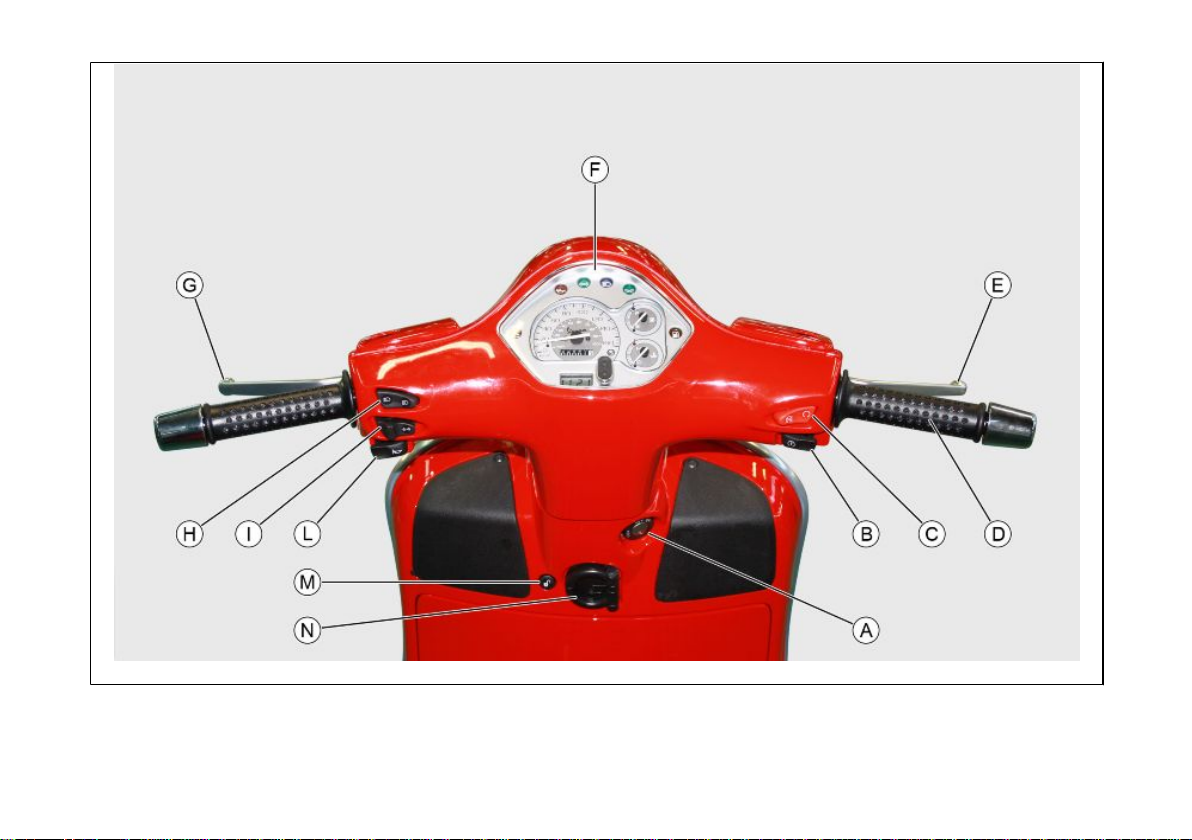
Dashboard................................................................................ 9
Analogue instrument panel....................................................... 10
Clock......................................................................................... 11
Key switch................................................................................. 12
Locking the steering wheel.................................................... 12
Releasing the steering wheel................................................ 13
Switch direction indicators........................................................ 13
Horn button............................................................................... 14
Light switch............................................................................... 14
Start-up button.......................................................................... 15
Engine stop button.................................................................... 15
The immobilizer system............................................................ 15
Keys...................................................................................... 16
Immobilizer device enabled indicator led.............................. 17
Operation............................................................................... 17
Programming the immobilizer system................................... 18
Accessing the fuel tank............................................................. 19
Opening the saddle............................................................... 20
Identification.............................................................................. 21
Rear top box opening................................................................ 22
USE.............................................................................................. 23
Checks...................................................................................... 24
Refuelling.................................................................................. 24
Tyre pressure............................................................................ 26
Shock absorbers adjustment.................................................... 27
Running in................................................................................. 28
Starting up the engine............................................................... 28
Precautions........................................................................... 29
Difficult start up......................................................................... 30
Stopping the engine.................................................................. 30
Stand......................................................................................... 31
Automatic transmission............................................................. 31
Safe driving............................................................................... 32
Rear rack.................................................................................. 34
MAINTENANCE........................................................................... 35
Engine oil level.......................................................................... 36
Engine oil level check............................................................ 36
Engine oil top-up................................................................... 36
Warning light (insufficient oil pressure)................................. 37
Engine oil change.................................................................. 37
Hub oil level.............................................................................. 39
Tyres......................................................................................... 41
Spark plug dismantlement........................................................ 42
Removing the air filter............................................................... 43
Cooling fluid level...................................................................... 44
Checking the brake oil level...................................................... 46
Battery....................................................................................... 47
Use of a new battery............................................................. 48
Long periods of inactivity.......................................................... 49
Fuses........................................................................................ 50
Front light group........................................................................ 54
Headlight adjustment............................................................. 57
Front direction indicators........................................................... 58
Rear optical unit........................................................................ 58
Rear turn indicators................................................................... 59
Rear-view mirrors...................................................................... 59
Front and rear disc brake.......................................................... 59
Puncture.................................................................................... 60
Periods of inactivity................................................................... 61
Cleaning the vehicle.................................................................. 62
TECHNICAL DATA...................................................................... 67
Toolkit....................................................................................... 72
SPARE PARTS AND ACCESSORIES........................................ 73
Warnings................................................................................... 74
SCHEDULED MAINTENANCE.................................................... 77
5

Vespa GTS 250 i.e.
Chap. 01
Vehicle
7

01_01
8
1 Vehicle

Dashboard (01_01)
A= Ignition key-switch
B= Starter button
C= Emergency stop switch RUN-OFF
D= Throttle grip
E= Front brake lever
F= Instrument panel
G= Rear brake lever
H= Light switch
I= Turn indicator switch
L= Horn button
M= Electric saddle opening button
N= Bag hook
9
1 Vehicle

01_02
Analogue instrument panel (01_02)
A= Digital clock
10
1 Vehicle

B= Odometer
C= Speedometer
D= Injection warning light
E= Engine oil pressure warning light
F= Turn indicators
G= High-beam warning light
H= Headlight warning light
I= Fuel gauge
L= Low fuel warning light
M= Coolant temperature gauge
N= Immobilizer LED
Clock (01_03)
Located in the instrument panel, it displays hours and minutes with 1 to 12-hour time,
AM or PM.
Operate the function selection button «B» and month, day and seconds are also dis-
played besides hours and minutes.
Toadjustthedifferentfunctions,selectthedesiredfunctionwithbutton«A»andadjust
with button «B». The time counter can be reset by pressing button «A» with the clock
in the seconds function.
11
1 Vehicle

01_03
The digital clock is powered by a battery (battery life is about 2 years); lift the whole
instrument panel to replace the battery. It is advisable to take your vehicle to an
Authorised Service Centre for this operation.
WARNING
DEAD BATTERIES ARE HARMFUL TO THE ENVIRONMENT. THEY MUST DIS-
POSED OF IN SUITABLE CONTAINERS AS PRESCRIBED BY THE REGULA-
TIONS IN FORCE.
01_04
Key switch (01_04)
LOCK = ignition disabled, extractable key, mechanical antitheft device enabled.
OFF = ignition disabled, extractable key, mechanical antitheft device disabled.
ON = Ready to ignition position, non-extractable key, mechanical antitheft device dis-
abled, lights on.
Locking the steering wheel
Turn the handlebar to the left (as far as it will go), turn the key to «LOCK» and remove
the key.
12
1 Vehicle

CAUTION
DO NOT TURN THE KEY TO «LOCK» OR «KEY OFF» WHILE RIDING.
Releasing the steering wheel
Reinsert the key and turn it to «OFF».
CAUTION
DO NOT TURN THE KEY TO «LOCK» OR «KEY OFF» WHILE RIDING.
01_05
Switch direction indicators (01_05)
Lever towards "S" = Left turn indicator is switched on;
Lever towards "D" = Right turn indicator is switched on;
The lever returns automatically to position "0" and the turn indicator "B" remains on;
press the lever to turn them off.
13
1 Vehicle

01_06
Horn button (01_06)
Push the «C» button to sound the horn.
01_07
Light switch (01_07)
0 = Low-beam and tail light
1 = High-beam and tail light
14
1 Vehicle

01_08
Start-up button (01_08)
Starter button "G"
01_09
Engine stop button (01_09)
0= OFF
1= RUN
The immobilizer system
In order to enhance theft protection, the vehicle is equipped with a «PIAGGIO IMMO-
BILIZER » electronic engine locking device that is activated automatically when the
ignition switch is removed. Upon start-up, the «PIAGGIO IMMOBILIZER» system
checks the starter key, and only if this key is recognised will the Immobiliser system
allow the vehicle to be started.
15
1 Vehicle

01_10
01_11
01_12
Keys (01_10, 01_11, 01_12)
Two types of keys are supplied together with the vehicle.
The red handgrip key «A» is the «MASTER» key.
Only a single copy of this key is supplied, which is necessary to program all your other
keys and for your dealer to perform some maintenance operations. For this reason it
is advised that it be used only in exceptional circumstances.
The blue key «B» (single copy supplied) is used for normal operations such as:
- engine start up
- glove-box opening
Together with the two keys, you will be given a CODE CARD bearing the same code
imprinted onto the two keys.
WARNING
LOOSING THE RED KEY PREVENTS ANY REPAIRS OF THE 'PIAGGIO IMMO-
BILIZER' SYSTEM AND THE ENGINE CONTROL UNIT.
WARNING
KEEPTHE'CODECARD'ANDTHEREDHANDGRIPKEYINASAFEPLACE(NOT
ON YOUR VEHICLE).
16
1 Vehicle

01_13
Immobilizer device enabled indicator led (01_13)
Activation of the "PIAGGIO IMMOBILIZER" system is signalled by a flashing «A»
indicator.Inordertoreducebatterydischarge,theindicatorLEDturnsoffautomatically
after48 hours ofuninterrupted functioning. Shouldthe system fail,different LED flash-
ing patterns will provide the Authorised Service Centre with information on the type
of fault detected.
Operation
Every time the starter key is removed in the "OFF" or "LOCK" position, the safety
system activates the immobilizer system. Turning the key to "ON" disables the engine
lock, provided that the safety system recognises the code transmitted by the key. If
the code is not recognised, turn the key first to "OFF" and then to "ON"; if the lock
cannotbe disabled, try with the other key supplied(red-coloured). If theengine cannot
be started, contact an Authorised Piaggio Service Centre, which is provided with
the electronic equipment required to detect and repair the system.
When additional keys are required, please note that data storage (up to 7 keys max.)
must be done on all keys, both new and existing ones.
Take your scooter to an Authorised Piaggio Service Centre carrying with you the
red-handgrip key and all the blue keys in your possession.
Thecodes of keys notsubmitted for the newprogramming procedure are deletedfrom
the memory. Any lost keys will therefore not be enabled to start the engine.
WARNING
EACH KEY HAS ITS OWN AND UNIQUE CODE, WHICH MUST BE STORED IN
THE SYSTEM CONTROL UNIT MEMORY.
17
1 Vehicle

VIOLENT SHOCKS MAY AFFECT THE ELECTRONIC COMPONENTS OF THE
KEY.
IF OWNERSHIP OF THE VEHICLE IS TRANSFERRED TO ANOTHER PERSON,
THE KEY WITH THE RED GRIP (AS WELL AS THE OTHER KEYS) AND THE
"CODE CARD" MUST BE ALSO TRANSFERRED TO THE NEW OWNER.
Programming the immobilizer system
Below is described the procedure to follow for programming the PIAGGIO IMMOBIL-
IZER system and/or for storing other key codes. The programming procedure should
be carried out with the engine stop switch set to «RUN».
Procedure start - red key
Insert the red ignition key in the switch key (in "OFF" position) and turn it to "ON". After
1 - 3 seconds, turn the key to «OFF » again and pull it out.
Intermediate step - blu key
Within ten seconds after pulling out the red key, insert the black key and promptly turn
it to «ON». After 1-3 seconds, turn the key to "OFF" again and pull it out.
In this way, a maximum of 3 blue keys can be programmed by repeating the above
procedure and keeping the indicated times.
18
1 Vehicle

Final step - red key
After pulling out the last blue key, insert the red key again and turn it to "ON" (this
operation should be performed within 10 seconds of pulling out the previous key).
Leave it in this position for 1 to 3 seconds and return it to the «OFF» position.
Proper programming check
Insert the red key disabling the transponder (i.e., tilt the key cap by 90°) and turn the
key to "ON". Perform the engine start-up operation. Ensure that the engine does not
start. Insert the blue key and repeat the start-up operation. Check that engine starts.
WARNING
SHOULDTHE ENGINE STARTWITH THE RED KEY(WITH TRANSPONDER OFF),
OR IN THE EVENT OF WRONG OPERATION DURING PROGRAMMING, REPEAT
THE PROCEDURE FROM THE BEGINNING.
01_14
Accessing the fuel tank (01_14, 01_15, 01_16)
Withthe key set to«OFF» or «ON», orwith engine on,itis possible toelectrically open
the saddle by pressing the button «C». If the saddle opening system does not work,
operate the emergency lever «A». Then, unscrew cap «B» and the fuel tank can be
reached.
19
1 Vehicle

01_15
01_16
01_17
Opening the saddle (01_17, 01_18)
Withthe key set to«OFF» or «ON», orwith engine on,itis possible toelectrically open
the saddle by pressing button «C». If the electric opening does not work, use the
emergency lever "A". When the key is set to «LOCK» the saddle cannot be opened.
20
1 Vehicle
Other manuals for GTS 250 I.E.
1
Table of contents
Other VESPA Motorcycle manuals