2
ZigBee Network Setup
ZigBee Device Guideline
ZigBee is a wireless communication protocol that is reliable, has low power consumption and has high
transmission efficiency. Based on the IEEE802.15.4 standard, ZigBee allows a large amount of devices to be
included in a network and are coordinated for data exchange and signal transmission.
Joining the ZigBee Network
As a ZigBee device, the Power Switch needs to join a ZigBee network to receive commands and transmit
energy consumption information. Follow the steps bellow to join the Power Switch into a ZigBee network.
1. Plug in the Power Switch into a power outlet.
2. Press and hold the function button for 10 seconds as the Power Switch resets and starts searching for
existing ZigBee network. Please make sure the permit-to-join feature on the router or coordinator of your
ZigBee network is enabled.
3. If the Power Switch successfully joins a ZigBee network, the LED Indicator will flash twice to confirm.
4. After joining the ZigBee network, the Power Switch will be registered in the network automatically. Please
check the ZigBee network coordinator, system control panel or CIE (Control and Indicating Equipment) to
confirm if joining and registration is successful.
5. If registration and joining to the network is unsuccessful, please check your ZigBee network coordinator,
system control panel or CIE setting to ensure the permit-to-join function is available, and then use the
Factory Reset function below to join the ZigBee network.
Binding with Controller
After joining the ZigBee network, the Power Switch can bind itself with a controller device which can be used
to turn on/off the Power Switch. To bind the Power Switch and the device:
1. Press and hold the Function Button for 3 seconds, then release the button. The Power Switch will send
binding request to the coordinator.
2. Refer to your controller manual to send binding request for the device within 16 seconds.
3. If binding is successful, the Power Switch LED indicator will flash 5 times to confirm. You can now use the
controller to adjust power output level for the Power Switch.
4. If binding is unsuccessful, please retry the binding process.
Removing Device from ZigBee Network (Factory Reset)
To remove the Power Switch from current ZigBee network, the Power Switch must be put to Factory Reset to
complete device removal. Factory Reset function will clear the Power Switch of its stored setting and
information and prompt the Power Switch to search for new ZigBee network.
Before removing device, make sure the Power Switch is within current ZigBee network signal range
1. Press and hold the function button for 10 seconds, then release the button to reset Power Switch.
2. Upon reset, the Power Switch will clear current ZigBee network setting and transmit signal to ZigBee
coordinator to remove itself from current ZigBee network. It will then actively search for available ZigBee
network again and join the network automatically.
ZigBee Router Device Capacity (PSS-29ZBSR / PSM-29ZBSR Only)
The Power Switch models with Router function allow other ZigBee devices to join the ZigBee Network through
the Router. The Power Switch Router has maximum capacity of 40 devices, including 10 routers; the Power
Switch Meter Router has maximum capacity of 10 devices including 5 routers.
Model No. Maximum ZigBee Device
+ Router Capacity Maximum ZigBee
Router Capacity
PSS-29ZBS 40 10
PSM-29ZBSR 10 5
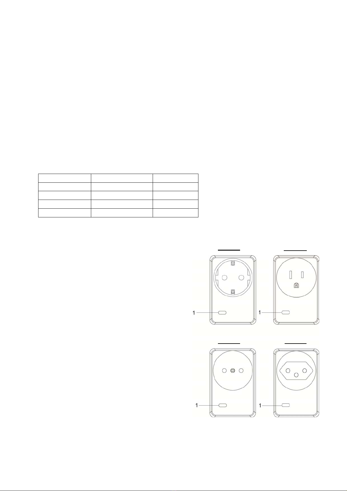
Operation
Installation
Plug the Power Switch into a power outlet, then Plug the appliance into the socket of the Power Switch.
The appliance must be in ON status.
IMPORTANT NOTE: The Power Switch does not have a backup battery and will be powered down
when AC power fails. DO NOT use the Power Switch as router for your security sensor or alarm control
devices such as Door Contact, PIR Sensor…etc., otherwise the sensors will lose connection to ZigBee
network if the Power Switch is disconnected from AC power. Plan the installation locations of these
security sensors without using the Power Switch and only use a router with backup battery for them. The
router function of the Power Switch should ONLY be used to provide signal range extension for other
Power Switches/Dimmer.