Vestamatic Vestaline SMI Series User manual

Subject to modifications.© Vestamatic GmbH 1/10
G
HOME ·VL-SMI-230-45
Art.-Nr.: 8900 001 GB 3117 A04 • Vestamatic GmbH • Dohrweg 27 • D-41066 Mönchengladbach • www.vestamatic.com
VL-SMI-230-45
Vestaline
SMI-Line motors Installation and Operating Instructions
VL-SMI-230-45/10Nm Art.-no.: 01066291
VL-SMI-230-45/20Nm Art.-no.: 01066301
VL-SMI-230-45/30Nm Art.-no.: 01066311
VL-SMI-230-45/50Nm Art.-no.: 01066321
Vestaline motors for controlling roller shutters.
G
HOME
8900 001 GB 3117 A04
1. Safety precautions
WARNING!
Important safety information.
Follow these instructions to ensure the
safety of persons. The instructions must
be stored.
– Contact a professional electrician to install
the motor, because the motor requires a
power supply of 230VAC, 50 Hz.
– Check the motor for signs of mechanical
damage after unpacking. If you notice
any shipping damage, do not start up the
motor and notify your supplier immedi-
ately.
– The motor should only be used for the
purpose specified by the manufacturer
(refer to the operating instructions). Any
changes or modifications thereof are not
permissible and will result in loss of all
warranty claims.
– Technical data can be found on the type
label of the tubular motor.
– If the motor cannot be operated without
presenting a hazard, it must be switched
off and prevented from being switched
on unintentionally.
– When performing work on the windows,
motor or connected shades, protect
them against unauthorised or uninten-
tional operation.
Ä
CONTENTS
1. Safety precautions (safety measures)
2. Short description (identification of products)
3. Scope of delivery
4. Intended use
5. Technical data
6. Standard Motor Interface
7. Installation, Assembly, Disassembly
8. Troubleshooting
9. Warranty
10. Maintenance
11. Disposal of waste
12. Service/Contact
13. Declaration of conformity
– Moving parts of the motor installed un-
der 2.5m above the floor level should be
protected.
– This device is not intended for use by
persons (including children) with reduced
physical, sensory or mental abilities or
lack of experience and/or lack of knowl-
edge, unless they are supervised by a
person responsible for their safety, or re-
ceived instructions on how the device is
to be used.
– Children should be supervised to ensure
that they do not play with the device.
– Children are not allowed, to play with
fixed controls. Keep remotes away from
children.
– The installation has to be checked fre-
quently for imbalance or of signs of wear,
damaged cables or springs, if applicable.
– Automatically controlled awnings have
to be disconnected from the supply net-
work, e.g. if maintenance work has to be
done close to them.
– Before the motor is installed, all un-
needed wires must be removed and all
devices which are not required for actua-
tion with a power drive must be put out of
operation.
– The actuating element of a hand release
is to be installed at a height of less than
1.8 m.
– The mains cable of this device cannot be
replaced. If the mains cable is damaged,
the device has to be discarded.

Subject to modifications.© Vestamatic GmbH 2/10
G
HOME ∙VL-SMI-230-45
Art.-Nr.: 8900 001 GB 3117 A04 • Vestamatic GmbH • Dohrweg 27 • D-41066 Mönchengladbach • www.vestamatic.com
2. Short description
Motor 45 mm tube diameter for roller shutters
Programmable upper and lower limit position
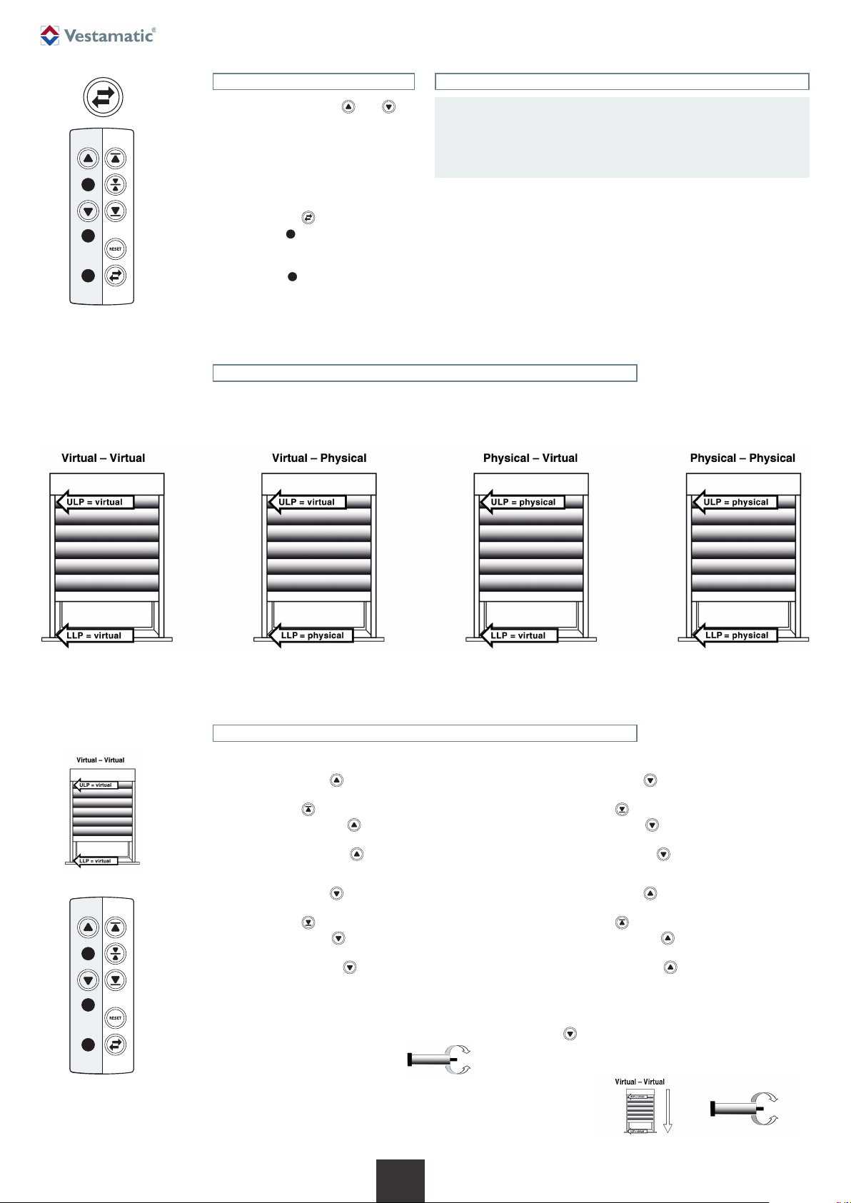
Limit positions can be virtual or physical (upper position)
Intermediate positions storage
Parallel connection allowed
Anti-block function
Simple setting of the limit position with the “VL-Progset-ME/SMI-230”
(Art.-no.: 54185775)
Re-synchronisation of physical limit positions
Cable 2.5 m white
4. Intended use
These types of tubular motor described in these manual is intended solely
for controlling roller shutters. These types of tubular motor cannot be used
in potentially explosive area.
These types of tubular motor are designed for using in a single sunshade
system.
3. Scope of delivery
Motor 45 mm tube diameter with 2.5 m connection cable
Operating instructions
Adapter set, comprising tube adapter / adapter ring
Mounting-kit, comprising safety clip / safety cotter
ATTENTION!
Pay attention to the following European
guidelines:
– The cables must conform to the applica-
ble VDE standard.
– If installing motors with a PVC H05VV-F
cable, the cable on surface-mounted out-
door installations and recessed-mounted
installations must be protected by a cable
conduit or cable duct.
– When installing the motor an all-pole dis-
connection with a contact gap of at least
3 mm per pole must be provided.
– The up and down directions of the
switch resp. button must be electrically
or mechanically locked against each
other. The changeover time for changing
the running direction (up/ down) must be
least 0.5 sec.
Ä
ATTENTION!
– Follow the safety instructions according
to EN 60335-2-97.
– Additional components for the implemen-
tation of the installation, such as adap-
tors and brackets must be chosen among
those offered by the producer. These
products are listed in the catalogue sup-
plied on request.
– When mounting the drive always use the
safest and most suitable tubular motor
and mounting bracket.
– For automatically actuated awnings a
minimum gap of 0.4 m to other parts in
the area must be maintained when the
awning is fully extended. By using as
an awning system the extended awning
must mainain a minimum height of 1.8 m.
Ä
IMPORTANT!
Any screws used to fix the rolling shutters
tube / awnings must in no way touch the
motor. Please refer to fig. 4.1 to 4.5.
Ä
WARNING!
Risk of injury due to improper installation
and commissioning.
Improper installation and commissioning may
lead to personal injury or property damage.
Therefore:
– When connecting the device, observe the
currently valid VDE standards (in particu-
lar DIN VDE 0100/0700), your local pow-
er company’s regulations and the current
accident prevention regulations.
– Connect the motor in accordance with the
wiring diagram.
– It is important for the safety of professional
electricians to follow the user instructions.
Please keep instructions for reference.
Ä
5. Technical data
Article VL-SMI-230-45/ 10Nm 20Nm 30Nm 50Nm
Art.-no.:
01066291 01066301 01066311 01066321
Torque (nominal) Nm 10 20 30 50
Output speed rpm 15 15 15 12
Tractive power kg 20 40 55 95
Supply voltage VAC 230 230 230 230
Frequency Hz 50 50 50 50
Rated power W 126 165 227 227
Rated current A 0,55 0,72 0,99 0,99
Running time Min. 4 4 4 4
Protection degree IP 44 44 44 44
Length L1 mm 461 481 522 551

Subject to modifications.© Vestamatic GmbH 3/10
G
HOME ∙VL-SMI-230-45
Art.-Nr.: 8900 001 GB 3117 A04 • Vestamatic GmbH • Dohrweg 27 • D-41066 Mönchengladbach • www.vestamatic.com
ATTENTION!
SMI-Motors must be connected to certified SMI-Actuators.
Parallel connection of tubular motor with electronic limit posi-
tion are allowed. The maximum switching contact load of the
connected control device (switch, motor control, actuator, etc.)
must be observed.
The combination of different operating modes is not allowed. To
change the operating mode from communication mode to switch
mode, push sequential the UP- and DOWN-button.
Also in the switch mode, we recommend the wiring between the
motor and the switch with a 4-wire cable.
Ä
Wiring diagram
ATTENTION!
Parallel connection of tubular motor with electronic limit position are allowed.
The maximum switching contact load of the connected control device (switch,
motor control, timer etc.) must be observed.
It is not allowed to combine the operation modes. To change the opera-
tion mode from communication mode to switch mode, a one-time sequen-
tially up and down button-press is necessary.
Ä
Note on laying SMI wires in custom cables!
The I+ and I- SMI wires can be laid in the motor connection line of the SMI
drive (as above) or in their own cable. It is not permitted to lay SMI wires
together with wires carrying other signals in one cable.
If SMI drives wired in parallel are supplied with electrical power from dif-
ferent phases, the SMI I+ and I- wires must be laid in a separate cable.
Ä
6. Standard Motor Interface
What is SMI?
SMI is the abbreviation for Standard Motor Interface. SMI has been de-
veloped to connect intelligent motors for roller shutters and sun protection
devices. SMI allows the transmission of messages from the control system
to the motor and vice versa. SMI allows products from different manufac-
turers to be combined. The SMI interface simplifies the use of highquality
solutions and increases the compatibility between standard motors and
controls from different manufacturers. Applications for sunscreens require
the greatest robustness and economy. SMI was developed to meet these
requirements.
7. Installation, assembly, disassembly
Fig. 4.1 Fig. 4.2 Fig. 4.3 Fig. 4.4 Fig. 4.5

Subject to modifications.© Vestamatic GmbH 4/10
G
HOME ∙VL-SMI-230-45
Art.-Nr.: 8900 001 GB 3117 A04 • Vestamatic GmbH • Dohrweg 27 • D-41066 Mönchengladbach • www.vestamatic.com
SMI drives on different AC phases
ATTENTION!
Parallel connection to the control lines I+ and I- while supplying pow-
er to the drives from different phases, is only permissible in telegram
operating mode.
Ä

Subject to modifications.© Vestamatic GmbH 5/10
G
HOME ∙VL-SMI-230-45
Art.-Nr.: 8900 001 GB 3117 A04 • Vestamatic GmbH • Dohrweg 27 • D-41066 Mönchengladbach • www.vestamatic.com
Electronic limit position setting with Installation tool
How to connect to an Installation tool (VL-Progset-ME/SMI-230/Art.-no.: 54185775).
IMPORTANT!
– Switch off the power supply. Connect the wire of the motor to the terminal
clamps of the installation tool.
– It is important that the motor-wire-colors correspond with the installa-
tion-tool-wire-colors, otherwise the motor turning direction could be set
incorrect. Switch on the power supply.
– The installation tool is not suitable for continuous operation and has only
been used for set the limit position.
Ä
The connection cable should be installed in an conduit to the junction box,
in compliance with the local building and electrical regulations. Avoid any
contact between moving objects and connection cables by routing the
cables according to figure 1.
Move the sunshade or screen completely down before disconnecting the
tube connectors.
Dissasembly of tubular shaft.
Place the mounting bracket to the desired position. Assembly of the motor
can be performed on both sides.
Slide the Adapter ring (A) on the adjustment ring (B). Be aware of the cor-
rect installation of the notch with the Adapter (D), (figure 2).
Place the tube adapter (E) on to the motor axle (F) and secure it with the
safety clip (G) that comes within the mounting-kit.
Be careful when sliding the tubular motor completely into the tubular shaft,
until the adapter ring is covered into the tubular shaft, (figure 3). Under no
circumstances external force should be applied to the motor in any way.
Place the motor head and tubular shaft into the mounting bracket and
check for proper fit. Secure the square pin of the motor head with the safe-
ty cotter that comes with the mounting-kit. Make sure to install the motor
in a position that the adjustment screws are accessible from the outside.
Assembly
Fig. 1
Disassembly
The workflow is the same as in the section “Assembly” (see above) but in
reverse order.
The setup of limit positions can be skipped.
Fig. 2
Fig. 3

Subject to modifications.© Vestamatic GmbH 6/10
G
HOME ·VL-SMI-230-45
Art.-Nr.: 8900 001 GB 3117 A04 • Vestamatic GmbH • Dohrweg 27 • D-41066 Mönchengladbach • www.vestamatic.com
Description of installation tool VL-Progset-ME/SMI-230
UP + green LED – Virtual upper limit set
yellow LED – Intermediate position
DOWN + red LED – Virtual lower limit set
green LED – Power
red LED – Change turning direction
Virtual upper limit
Intermediate position
Virtual lower limit
Reset
Change turning direction
Left side: Motor control Right side: Motor programming
Motor control Motor programming
Button Control motor in UP direction
Hold down the button to move the motor in
UP direction.
green
Button Set “Virtual upper limit position”.
LED green LED – Virtual upper limit position:
OFF when no “Virtual upper limit” is set.
Blinking when “Virtual upper limit” or „Reset“
programming is in progress.
Lit solid when “Virtual upper limit” programming
sequence has completed.
LED yellow LED – Intermediate position:
yellow
Button Set “Intermediate position”.
OFF when no “Intermediate position” is set.
Blinking when “Intermediate position”
programming is in progress.
Lit solid when “Intermediate position” programming
sequence has been completed.
Button Control motor in DOWN direction
Hold down the button to move the motor in
DOWN direction.
red
Button Set “Virtual lower limit position”.
LED red LED – Virtual lower limit position:
OFF when no “Virtual lower limit” is set.
Blinking when “Virtual lower limit” or „Reset“
programming is in progress.
Lit solid when “Virtual lower limit” programming
sequence has completed.
LED green LED – Power:
OFF when powerless (it is safe to connect
a motor to the Installation Tool).
green
Button Reset
Lit solid when attached to mains 230VAC.
LED red LED – Change turning direction:
OFF when no “Change turning direction”
is used.
red
Button Change motor turning direction.
Blinking when “Change motor turning direction”
programming sequence is in progress.
Lit solid when “Change motor turning direction”
programming sequence has completed.

Subject to modifications.© Vestamatic GmbH 7/10
G
HOME ·VL-SMI-230-45
Art.-Nr.: 8900 001 GB 3117 A04 • Vestamatic GmbH • Dohrweg 27 • D-41066 Mönchengladbach • www.vestamatic.com
Changing motor turning direction
– Hold down the button or to
check the motor turning direction.
– When the motor reacts in opposite direc-
tion (when motor goes down when you
press up and vice-versa), you need to
change the motor direction. Motor direc-
tion can only be changed during installa-
tion phase, when no limit positions are set.
– Press the button shortly.
– The red LED starts blinking as long
as the change motor turning direction
process is in progress.
– The red LED lit solid if the process
is finished.
UP
DOWN
red Change turning
direction
green
yellow
Setting electronic limit position
ATTENTION!
– The motor starts to move with a short delay time during
installationphase, when no limit positions are set.
–Conditions to use the physical (automatic) limit position
settings: The upper limit stop has to be installed.
Ä
Electronic limit position setting combination
ULP = is an abbreviation for Upper Limit Position.
LLP = is an abbreviation for Lower Limit Position.
Following combinations virtual/physical limit position settings are possible:
Both upper and lower limit
position are virtual.
Upper limit position is virtual,
lower limit position is physical.
Upper limit position is physical,
lower limit position is virtual.
Both upper and lower limit
position are physical.
UP
DOWN
red Change turning
direction
green
yellow
Virtual – Virtual
Option: start with lower limit position setting
– Hold down the button to move the motor in the re-
quested lower limit position.
– Press the button shortly.
– The red LED of button starts blinking as long as the
limit setting process is in progress.
– The red LED of button lit solid if the process is
finished.
– Hold down the button to move the motor in the re-
quested upper limit position.
– Press the button shortly.
– The green LED of button starts blinking as long as
the limit setting process is in progress.
– The green LED of button lit solid if the process is
finished.
– The motor needs the following complete movement
(figure 1) to memorize the limit position. (Hold down the
button to move the motor in the requested direction).
Themotor willgivea feedback(short up/down movement)
to confirm that the installation procedure has ended.
Advice: start with upper limit position setting
– Hold down the button to move the motor in the re-
quested upper limit position.
– Press the button shortly.
– The green LED of button starts blinking as long as
the limit setting process is in progress.
– The green LED of button lit solid if the process is
finished.
– Hold down the button to move the motor in the re-
quested lower limit position.
– Press the button shortly.
– The red LED of button starts blinking as long as the
limit setting process is in progress.
– The red LED of button lit solid if the process is
finished.
– The motor will give a feedback (short up/down move-
ment) to confirm that the installation procedure has
ended.
figure 1

Subject to modifications.© Vestamatic GmbH 8/10
G
HOME ·VL-SMI-230-45
Art.-Nr.: 8900 001 GB 3117 A04 • Vestamatic GmbH • Dohrweg 27 • D-41066 Mönchengladbach • www.vestamatic.com
Option: start with lower limit position setting
– Hold down the button to move the motor in the re-
quested lower limit position.
– Press the button shortly.
– The red LED of button starts blinking as long as the
limit setting process is in progress.
– The red LED of button lit solid if the process is finished.
– Hold down the button till motor stops automatically
due to obstacle detection. Upper physical limit position
is now set.
– The motor needs the following complete movements
(figure 3) to memorize the limit position. (Hold down the
button or to move the motor in the requested
direction). The motor will give a feedback (short up/down
movement) to confirm that the installation procedure has
ended.
Physical – Virtual
Advice: start with upper limit position setting
– Hold down the button till motor stops automatically
due to obstacle detection. Upper physical limit position
is now set.
– Hold down the button to move the motor in the re-
quested lower limit position.
– Press the button shortly.
– The red LED of button starts blinking as long as the
limit setting process is in progress.
– The red LED of button lit solid if the process is finished.
– The motor needs the following complete movements
(figure 2) to memorize the limit position. (Hold down the
button or to move the motor in the requested
direction). The motor will give a feedback (short up/down
movement) to confirm that the installation procedure has
ended.
UP
DOWN
red Change turning
direction
green
yellow
figure 2 figure 3
Advice: start with upper limit position setting
– Hold down the button to move the motor in the re-
quested upper limit position.
– Press the button shortly.
– The green LED of button starts blinking as long as
the limit setting process is in progress.
– The green LED of button lit solid if the process is
finished.
– Hold down the button till motor stops automatically
due to obstacle detection. Lower physical limit position is
now set.
– The motor needs the following complete movements
(figure 4) to memorize the limit position. (Hold down the
button or to move the motor in the requested
direction). The motor will give a feedback (short up/down
movement) to confirm that the installation procedure has
ended.
Virtual – Physical
Option: start with lower limit position setting
– Hold down the button till motor stops automatically
due to obstacle detection. Lower physical limit position is
now set.
– Hold down the button to move the motor in the re-
quested upper limit position.
– Press the button shortly.
– The green LED of button starts blinking as long as
the limit setting process is in progress.
– The green LED of button lit solid if the process is
finished.
The motor needs the following complete movement
(figure 5) to memorize the limit position. (Hold down the
button to move the motor in the requested direction).
The motor will give a feedback (short up/ down movement)
to confirm that the installation procedure has ended.
UP
DOWN
red Change turning
direction
green
yellow
figure 4 figure 5

Subject to modifications.© Vestamatic GmbH 9/10
G
HOME ·VL-SMI-230-45
Art.-Nr.: 8900 001 GB 3117 A04 • Vestamatic GmbH • Dohrweg 27 • D-41066 Mönchengladbach • www.vestamatic.com
Motor – RESET
1. Clear – LED status
Clear the installation tool LED-status.
Keep the RESET button pressed till
the LEDs turn off.
2. Delete the limit position settings
of the motor
Press the RESET button , till the
LEDs start blinking.
The LEDs keep blinking as long as the
motor reset process is in progress.
When the RESET process is finished,
the LEDs turn off, the motor limit posi-
tions have been cleared, and can be set
again.
The motor will shortly move during the
RESET sequence.
RESET
NOTE!
Tubular motor might be switched off before reaching the limit position:
Extraordinary large increases of load (anti-block-function) – obstacles,
sunshade system keeps jamming, tubular motor is overloaded.
Remedy action:
– Removing the obstacle.
– Check the mechanical parts of the sunshade system.
– Use the correct tubular motor (rated torque – tractive power) according the
spezification of the sunshade system.
I
UP
DOWN
red
Intermediate
position
green
yellow
Save intermediate position
– Before setting the intermediate posi-
tion, the upper and lower limit position
should be set and confirmed.
– Press the button or = self-lock-
ing. Simply press the opposite button to
stop the motion.
– Press the button “intermediate position”
shortly.
– The yellow LED starts blinking as
long as the setting process is in pro-
gress.
– The yellow LED lit solid if the process
is finished.
– The motor will give a feedback (short
DOWN/UP movement) to confirm that
the installation procedure has ended.
– When an intermediate position is pro-
grammed, the motor reaction is de-
pendable of how long the UP/DOWN
button is pressed.
– Press the button or short = inter-
mediate position.
– Press the button or long (> as
1 sec.) = overrun the intermediate po-
sition.
– The intermediate position can be
change/overwritten at any time.
Option: start with lower limit position setting
– Hold down the button till motor stops automatically
due to obstacle detection. Lower physical limit position is
now set.
– Hold down the button till motor stops automatically
due to obstacle detection. Upper physical limit position
is now set.
– The motor needs the following complete movements
(figure 7) to memorize the limit position. (Hold down
the button or to move the motor in the request-
ed direction). The motor will give a feedback (short
up/down movement) to confirm that the installation pro-
cedure has ended.
Physical – Physical
Advice: start with upper limit position setting
– Hold down the button till motor stops automatically
due to obstacle detection. Upper physical limit position
is now set.
– Hold down the button till motor stops automatically
due to obstacle detection. Lower physical limit position is
now set.
– The motor needs the following complete movements
(figure 6) to memorize the limit position. (Hold down
the button or to move the motor in the request-
ed direction). The motor will give a feedback (short
up/down movement) to confirm that the installation pro-
cedure has ended.
UP
DOWN
red Change turning
direction
green
yellow
figure 6 figure 7

Subject to modifications.© Vestamatic GmbH
Art.-Nr.: 8900 001 GB 3117 A04 • Vestamatic GmbH • Dohrweg 27 • D-41066 Mönchengladbach • www.vestamatic.com
10/10
G
HOME ∙VL-SMI-230-45
8. Troubleshooting
Problem Possible cause Solution
Motor is not responding. 1. No mains voltage. 1. Check mains voltage.
2. Connection error. 2. Check connections (see wiring diagram).
3. Cutoff by internal temperature fuse. 3. Allow the motor to cool down for 20 min.
Motor starts slowly or makes too
much noise.
1. Connection error. 1. Check connections.
2. Installation error or undersized motor selected. 2. Check installation and motor load.
Motor rotation direction is wrong. Motor connection cables are reversed. Disconnect the supply line from the power, and swap
the black and brown conductors of the motor cable at
the controller.
Motor stops while moving up or
downwards.
1. Preset endpoint reached. 1. Set the end limits again, according to the instructions.
2. Cutoff by internal temperature fuse. 2. Allow the motor to cool down for 20 min.
Motor stops while moving upwards. Iced roller shutter or obstacle in running rail. Remove icing or obstacle. Release the roller shutter by
steering the motor in downward direction.
The motor is maintenance-free.
10. Maintenance
The disposal of electrical equipment and batteries in household
waste is strictly forbidden.
The symbol (dustbin crossed out, in line with WEEE Appendix IV)
indicates separate collection of electrical and electronic products in
EU countries. Do not dispose of the device or battery in your house-
hold waste. Ask your town or local council about the return and col-
lection systems available in your area to dispose of this product.
É
11. Disposal of waste
9. Warranty
Principally, the General Terms and Conditions of the manufacturer, Ves-
tamatic GmbH apply. The terms and conditions are part of the sales doc-
uments and handed over to the operator upon delivery. Liability claims for
personal or material damages are excluded when they can be attributed to
one or more of the following causes:
– Unintended use of the product.
– Opening of the product by the customer.
– Improper installation, commissioning, or operation of the product.
– Non-compliance with the specifications.
– Non-observance of the safety provisions and instructions of the Oper-
ating Instructions.
– Operation of the product with improperly installed connections, defec-
tive safety devices or improperly installed safeguards.
– Modifications to the product.
12. Support/Contact
Vestamatic GmbH
Dohrweg 27
41066 Mönchengladbach
Germany
Phone: +49 2161 / 29 408-0
This manual suits for next models
8
Table of contents
Other Vestamatic Engine manuals
Popular Engine manuals by other brands

Alpha Motors
Alpha Motors WSER50 Series quick start guide

IEF Werner
IEF Werner Module 68 operating instructions

Cadillac
Cadillac 1954 series Service manual

Predator Engines
Predator Engines PREDATOR 212 owner's manual

Detroit Diesel
Detroit Diesel Series 60 DDEC VI troubleshooting guide

Mercury Racing
Mercury Racing HP565 manual