manuals.online logo
Brands
  1. Home
  2. •
  3. Brands
  4. •
  5. YOODA
  6. •
  7. Engine
  8. •
  9. YOODA 35 R/S Series User manual

YOODA 35 R/S Series User manual

R/S motors are motors with two-way communication and a
radio receiver. They are meant for automating internal blinds,
roller shutters or awnings. Mechanical limit switches enable
for the motor to stop in a fixed position of the blind.
Motors are compatible with all YOODA SMART HOME devices.
Radio receiver memory:
up to 10 transmitters
Maximal time of uninterrupted work:
4 min.
Power supply:
230 V / 50 Hz
Working temperature:
from -5°C to 50°C
Safety degree:
IP 44
35R/S tubular motor
Non-compliance with the following instructions can not only present risk to life and health, but also affect the correct operation of the entire roller shutter.
It is recommended to abide by the instructions. Tubular motors are compatible with all YOODA SMART HOME devices.
R/S motors are motors with two-way communication.
35, 45 R/S SERIES MOTORS
www.sukcesgroup.pl
1. Technical data
1
Maximal work time of the motor is about 4 minutes. After that time thermal protection will turn on, which will cause the
disconnection of the engine protecting it from overheating. You must wait for about 20 minutes after thermal switch has
turned on, so that the motor comes back to the normal operating mode.
power supply cord radio receiver
limit switches
limit positions
regulator
engine brake gearing
antenna
capacitor
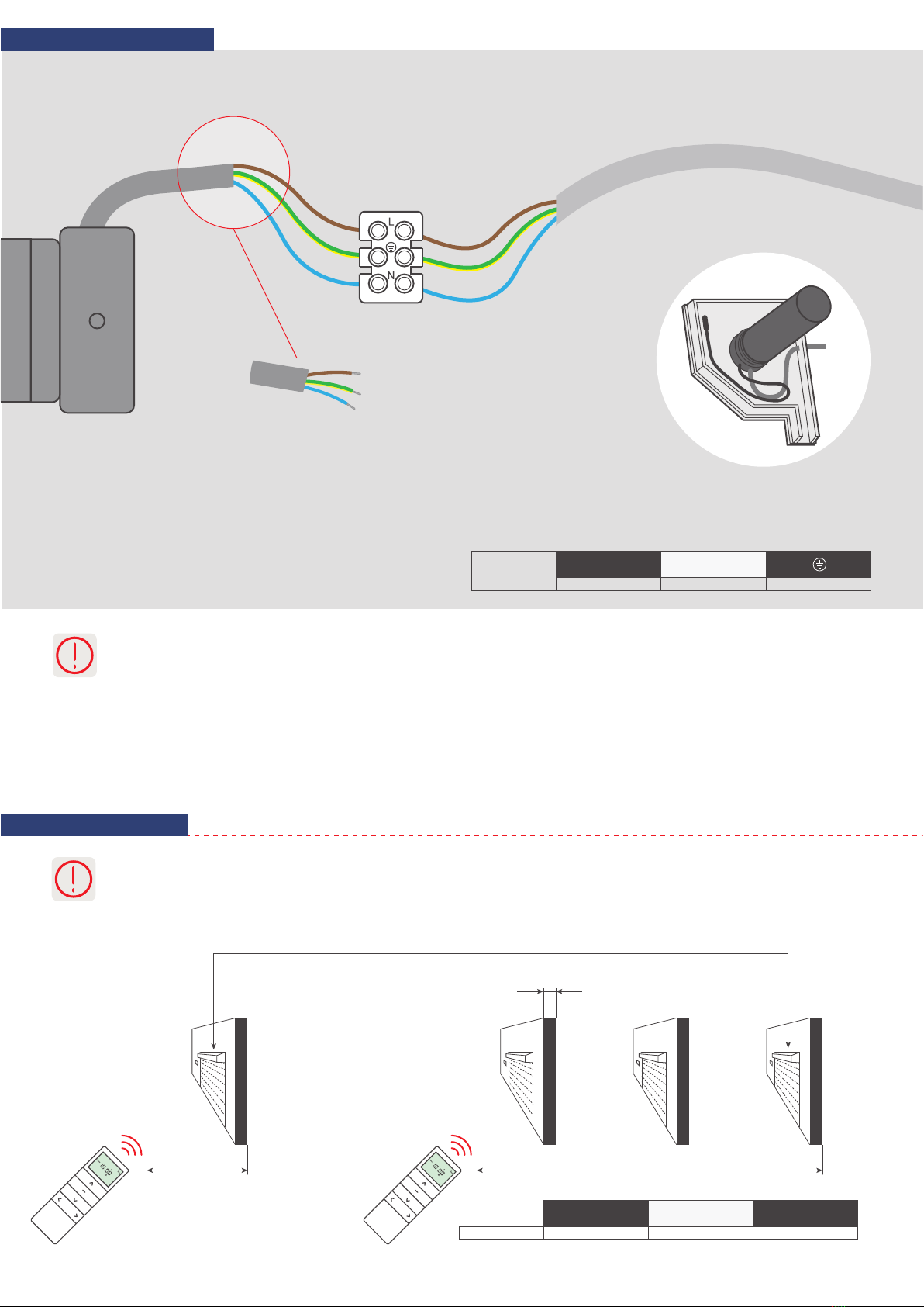
Motor should be mounted in places protected against adverse weather conditions.
2. Safety
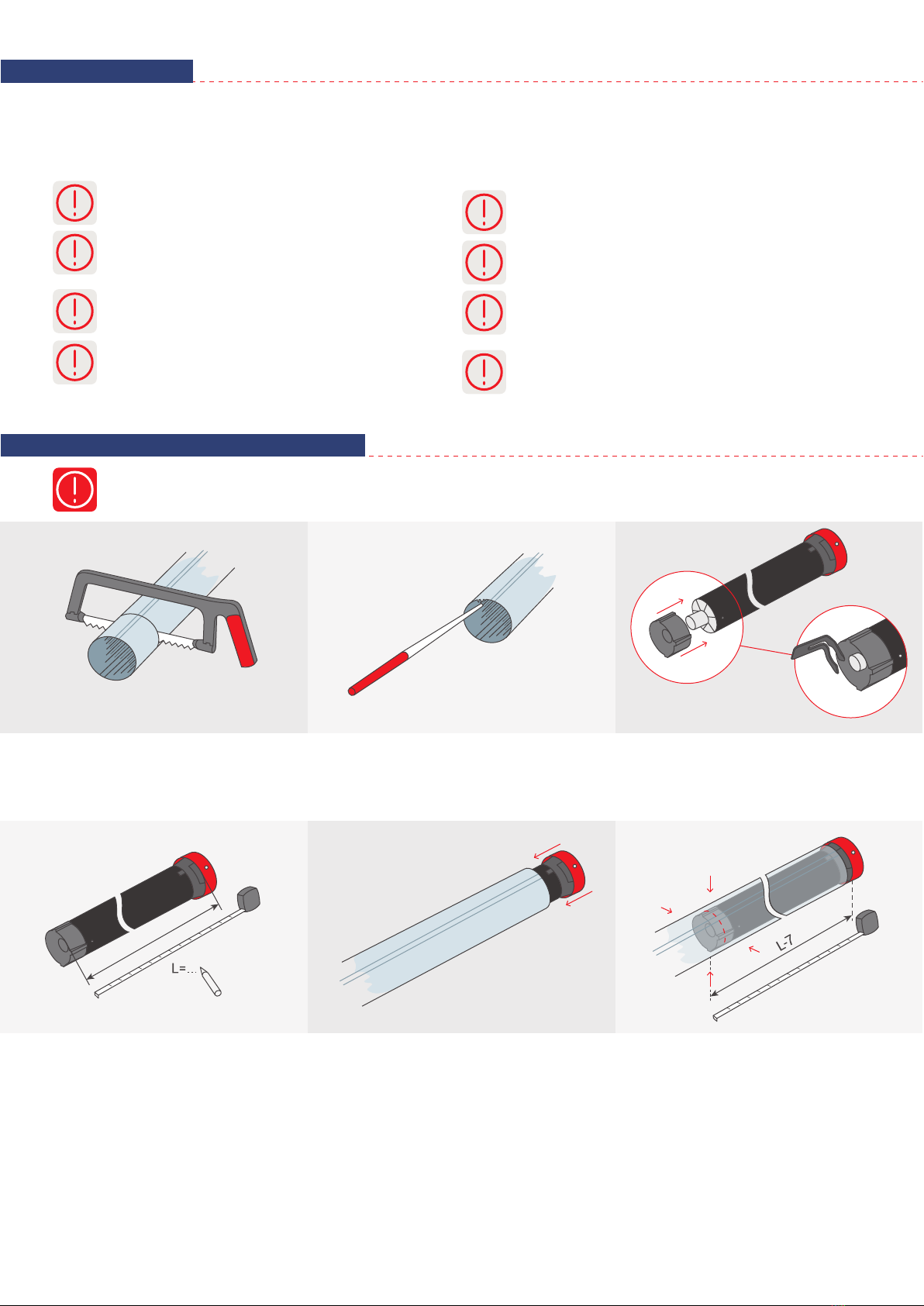
3. Motor assembly in a roller tube
Before starting assembling and using the device it is necessary to read the following instruction. The installer must abide by the
standards and the regulations effective in the country, where the device will be mounted and inform users on the conditions of use and
maintenance of the device. Non-compliance with the following instructions can not only present risk to life and health, but also affect the
correct operation of the entire roller shutter. This also results in the loss of warranty rights.
Torque should be suitable to the weight of the armour.
Wires of the motor should be mounted in a way to
prevent condensed water from getting inside and
so that a working roller blind does not damage them.
Check regularly the signs of wear of components
responsible for correct motor operation.
Turn off mains power before performing any activity
connected with installation or maintenance.
Keep contact of the motor with liquids to a minimum.
Do not use tools while placing the motor in a roller
tube.
Be careful not to damage the motor during assembly
of a driver.
Keep an eye on children, so that they do not play with
the motor and its control system. Mobile transmitters
should be kept away from them.
2
1. Cut the roller tube
to a suitable size.
2. Remove all filings and burrs
from the edges of the roller tube.
3. Mount the adaptation
on the motor.
4. Measure the length L between inner edge of
the cylinder head and the end of the driver.
5. Place the motor in the roller tube in
a way that the edge of the roller tube sticks
to the inner edge of the cylinder head.
Anchor the roller tube to the driver with four
screws or rivets, placed in a distance L-7 mm
from the inner edge of the cylinder head.
4. Connection
5. Range
3
Installation should be carried out by authorized persons, i.e. having appropriate permissions (min. SEP to 1 kV). The device
is meant to be installed in places protected against adverse weather conditions. The device should be mounted in
accordance with regulations and standards applicable in Poland and in EU. Wires connecting the receiver of electric energy
with power source should be protected against overload and short circuit with protecting devices, which will turn off the
power supply automatically. The device should be powered via a separate line, protected by a fast-acting fuse (e.g. WTS,
S-cl.B), and never by a slow-acting fuse (cl. C or D). Protecting the system with such a fuse can cause loss of warranty
rights. While connecting the device with power supply, you must use wires with suitable gauge. While choosing them, use
tables with long-term load capacity of conductors with direct or alternating current.
230 V AC
phase wire neutral wire earth conductor
LN
brown phase wire
Power supply wire and
antenna mounting method.
230 V / 50 Hz
yellow-green earth conductor
blue neutral wire
The range given by the manufacturer is a variable value, depending on the conditions in the environment in which the device
works. Factors such as building structure, signal interference from other devices, etc. affect range.
230 V / 50 Hz 200 m 30 m 433,92 MHz
L1
open area L2
indoors System operation
frequency
20
Remote-controlled roller blind with a motor
L2L1
1. The receiver can be controlled by max. 10 transmitters.
2. A break between succesive button presses longer than 6 seconds, will automatically cause the exit from programming
mode without saving the changes.
9. Programming of the next transmitter
METHOD NO. 1:
6. Programming of the first transmitter
4
1. A break between succesive button presses longer than 6 seconds, will automatically cause the exit from programming
mode without saving the changes.
7. Changing the direction of motor operation
8. Limit positions adjustment
The motor will make a
sound. The blind will make
short up/down moves.
Press and hold STOP
button on the remote
control for 2 sec.
The blind will make two
short up/down moves. The
motor will make a few short
sound signals.
DOWN button controls
lifting of the blind.
Press and hold
UP and DOWN buttons
for 2 seconds.
The blind will make
short up/down moves.
DOWN button controls
lowering the blind.
Press P2 programming button
on remote control A.
Remote control
has been programmed.
The motor will make
a sound. The blind
will make short
up/down moves.
The motor will make
a sound. The blind
will make short
up/down moves.
The blind will make two short
up/down moves. The motor
will make a few short sound
signals.
Press P2
programming
button on remote
control A.
Press P2
programming
button on remote
control B.
Turn on power supply.
You must adjust limit positions manually, with a regulator from your set.
Decreasing the range
Increasing the range
Direction of engine rotation
Direction of adjustment of
the limit switch
To adjust lower or upper limit position, put the blind in motion of
closing or opening, until it stops in a factory set position. To
increase this range, use the proper knob and move it towards „+”.
If the range is too big, decrease it by moving it towards „-”.
METHOD NO. 1:
METHOD NO. 2:
METHOD NO. 3:
5
Press P2 programming button
on remote control A.
Remote control
has been programmed.
Remote control
has been programmed.
The motor will make a sound.
The blind will make short
up/down moves.
The motor will make
a sound. The blind
will make short
up/down moves.
The blind will make two short
up/down moves. The motor
will make a few short sound
signals.
Press P2
programming
button on remote
control A.
Press and hold
STOP button
on remote
control B for
2 seconds.
The motor will make a sound.
The blind will make short
up/down moves.
The blind will make two short
up/down moves. The motor
will make a few short sound
signals.
Press and hold
STOP button
for 2 seconds on
the remote control
that is being
programmed.
10. Deleting the next transmitter
The motor will make
a sound. The blind
will make short
up/down moves.
The motor will make
a sound. The blind will
make short
up/down moves.
The blind will make two short
up/down moves. The motor
will make a few short sound
signals.
Press P2
programming button
on remote control A.
Press P2
programming
button on remote
control B.
Press P2 programming button
on remote control A.
Remote control
has been deleted.
METHOD NO. 2:
METHOD NO. 3:
Press P2 programming
button on remote control A.
Remote control
has been deleted.
Remote control
has been deleted.
The motor will make
a sound. The blind
will make short
up/down moves.
The motor will make
a sound. The blind will
make short
up/down moves.
The blind will make two short
up/down moves. The motor
will make a few short sound
signals.
Press P2
programming button
on remote control A.
Press and hold
STOP button on
remote control
B for 2 seconds.
The motor will
make a sound. The blind will
make short up/down moves.
Turn on power supply. The blind will
make two short up/down
moves. The motor will
make a few short
sound signals.
Press and hold
STOP button on the
programmed remote
control for 2 seconds.
Turn on power supply.
6
11. Deleting all transmitters
12. Activation of impulse mode
13. Controlling with the application
The motor will make a sound.
The blind will make short
up/down moves.
The motor will make
a sound. The blind
will make short
up/down moves.
The blind will make
two short up/down moves.
The motor will make a few
short sound signals.
Press
STOP button.
Press P2
programming
button.
Press P2 programming
button on remote control A.
All active transmitters
have been deleted.
1. A break between succesive button presses longer than 6 seconds, will automatically cause the exit from programming
mode without saving the changes.
2. To turn on the impulse mode, follow the procedure below and to turn it off - repeat the same procedure.
3. The impluse function is carried out in the following way: short pressing of UP or down button causes fluctuating motor
operation and holding the button for more than 2 seconds causes steady motor operation.
The blind will make short
up/down moves.
Press and hold
UP and DOWN buttons
simultaneously
for 5 seconds.
Place the motor in the
upper limit position.
Press and hold UP and
STOP buttons
simultaneously
for 2 seconds.
The motor will make a move in
the direction of the lower limit
position, then in the direction of
the upper limit position.
The blind will make short moves
in both directions, confirming
that limit positions have been
programmed.
Press STOP button
on the remote control.
If the blind makes a short
move in both directions and
the motor makes a sound,
impulse mode is ON.
If the blind makes two short
moves in both directions and
the motor makes a sound
three times, impulse
mode is OFF.
To percentage control the roller blind positions, you must programme upper and lower limit positions.

This manual suits for next models

1

Other YOODA Engine manuals

YOODA DVH55B User manual

YOODA

YOODA DVH55B User manual

YOODA 25TE Series User manual

YOODA

YOODA 25TE Series User manual

YOODA 35EVY Series User manual

YOODA

YOODA 35EVY Series User manual

YOODA Smart Home 45 EM/S Series User manual

YOODA

YOODA Smart Home 45 EM/S Series User manual

YOODA Ortino DT72TE Series User manual

YOODA

YOODA Ortino DT72TE Series User manual

YOODA CORTINO DT72LE Series User manual

YOODA

YOODA CORTINO DT72LE Series User manual

YOODA 45 EZ/Y Series User manual

YOODA

YOODA 45 EZ/Y Series User manual

YOODA 35EV/S Series User manual

YOODA

YOODA 35EV/S Series User manual

YOODA 35R User manual

YOODA

YOODA 35R User manual

YOODA Cortino DT72EN User manual

YOODA

YOODA Cortino DT72EN User manual

YOODA 18LE Series User manual

YOODA

YOODA 18LE Series User manual

Popular Engine manuals by other brands

Stober C0 operating manual

Stober

Stober C0 operating manual

Doosan MD Series installation instructions

Doosan

Doosan MD Series installation instructions

MTU 12 V 4000 C20 operating instructions

MTU

MTU 12 V 4000 C20 operating instructions

Bosch Rexroth MKE Series Project planning manual

Bosch

Bosch Rexroth MKE Series Project planning manual

Navistar N13 Service manual

Navistar

Navistar N13 Service manual

Toshiba H9 ASD Simple Start Guide

Toshiba

Toshiba H9 ASD Simple Start Guide

Kohler Courage XT-6 Service manual

Kohler

Kohler Courage XT-6 Service manual

motortronics ABC-100 Installation & operation manual

motortronics

motortronics ABC-100 Installation & operation manual

ISM SV-250 instruction manual

ISM

ISM SV-250 instruction manual

Siemens SIEMOSYN 1FU8 Planning guide

Siemens

Siemens SIEMOSYN 1FU8 Planning guide

D-MOTOR LF39 owner's manual

D-MOTOR

D-MOTOR LF39 owner's manual

Aluprof DM45S-40/15 manual

Aluprof

Aluprof DM45S-40/15 manual

Motion CM-36 manual

Motion

Motion CM-36 manual

POLYSPEDE OC2-500 manual

POLYSPEDE

POLYSPEDE OC2-500 manual

SH Engines GF-6 manual

SH Engines

SH Engines GF-6 manual

Perkins 1204F-E44TA Systems operation testing and adjusting

Perkins

Perkins 1204F-E44TA Systems operation testing and adjusting

Lycoming IO-390-D Series Installation and operation manual

Lycoming

Lycoming IO-390-D Series Installation and operation manual

Rotax 914 series installation manual

Rotax

Rotax 914 series installation manual

manuals.online logo
manuals.online logoBrands
  • About & Mission
  • Contact us
  • Privacy Policy
  • Terms and Conditions

Copyright 2025 Manuals.Online. All Rights Reserved.