Subject to modifications.© Vestamatic GmbH 1/7
G
HOME ∙VL-ME-230-45
Art.-Nr.: 1100 001 GB 1518 A08 • Vestamatic GmbH • Dohrweg 27 • D-41066 Mönchengladbach • www.vestamatic.com
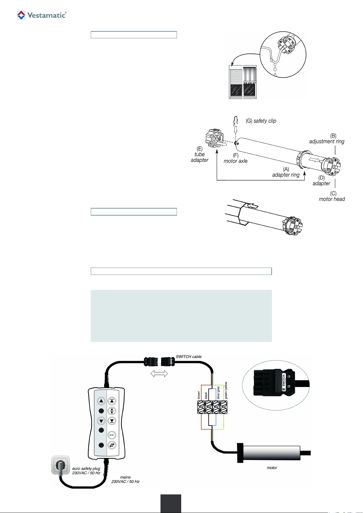
IMPORTANT!
Any screws used to fix the rolling shutters tube / awnings must in
no way touch the motor. Please refer to fig. 4.1 to 4.5.
Ä
VL-ME-230-45
Vestaline
E-Line motors Installation and Operating Instructions
VL-ME-230-45/10Nm Art.-no.: 01066110
VL-ME-230-45/20Nm Art.-no.: 01066120
VL-ME-230-45/30Nm Art.-no.: 01066130
VL-ME-230-45/50Nm Art.-no.: 01066140
Vestaline motors for controlling roller shutters.
G
HOME
1100 001 GB 1518 A08
1. Safety precautions
WARNING!
Important safety information.
Follow these instructions to ensure the safety of persons.
The instructions must be stored.
– Contact a professional electrician to install the motor, because
the motor requires a power supply of 230VAC, 50 Hz.
– Check the motor for signs of mechanical damage after un-
packing. If you notice any shipping damage, do not start up
the motor and notify your supplier immediately.
– The motor should only be used for the purpose specified by
the manufacturer (refer to the operating instructions). Any
changes or modifications thereof are not permissible and will
result in loss of all warranty claims.
– Technical data can be found on the type label of the tubular
motor.
– If the motor cannot be operated without presenting a hazard,
it must be switched off and prevented from being switched
on unintentionally.
– When performing work on the windows, motor or connected
shades, protect them against unauthorised or unintentional
operation.
– Moving parts of the motor installed under 2.5m above the
floor level should be protected.
– This motor is not intended for use by persons (including chil-
dren) with reduced physical, sensory or mental abilities or
lack of experience and/or lack of knowledge, unless they are
supervised by a person responsible for their safety, or re-
ceived instructions on how the device is to be used.
– Children should be supervised to ensure that they do not
play with the device.
– Children are not allowed, to play with fixed controls. Keep
remotes away from children.
– The installation has to be checked frequently for imbalance
or of signs of wear, damaged cables or springs, if applicable.
– Automatically controlled awnings have to be disconnected
from the supply network, e.g. if maintenance work has to be
done close to them.
Ä
CONTENTS
1. Safety precautions (safety measures)
2. Short description (identification of products)
3. Scope of delivery
4. Intended use
5. Technical data
6. Installation, Assembly, Disassembly
7. Troubleshooting
8. Warranty
9. Maintenance
10. Disposal of waste
11. Declaration of conformity
12. Service/Contact
– Before the motor is installed, all unneeded wires must be
removed and all devices which are not required for actuation
with a power drive must be put out of operation.
– The actuating element of a hand release is to be installed at
a height of less than 1.8 m.
– The mains cable of this device cannot be replaced. If the
mains cable is damaged, the device has to be discarded.
ATTENTION!
Pay attention to the following European guidelines:
– The cables must conform to the applicable VDE standard.
– If installing motors with a PVC H05VV-F cable, the cable on
surface-mounted outdoor installations and recessed-mounted
installations must be protected by a cable conduit or cable duct.
– When installing the motor an all-pole disconnection with a
contact gap of at least 3 mm per pole must be provided.
– The up and down directions of the switch resp. button must
be electrically or mechanically locked against each other.
The changeover time for changing the running direction
(up/down) must be least 0.5 sec.
Ä
ATTENTION!
– Follow the safety instructions according to EN 60335-2-97.
– Additional components for the implementation of the installa-
tion, such as adaptors and brackets must be chosen among
those offered by the producer. These products are listed in
the catalogue supplied on request.
– When mounting the drive always use the safest and most
suitable tubular motor and mounting bracket.
– For automatically actuated awnings a minimum gap of 0.4 m
to other parts in the area must be maintained when the awn-
ing is fully extended. By using as an awning system the ex-
tended awning must mainain a minimum height of 1.8 m.
Ä
WARNING!
Risk of injury due to improper installation and commissioning.
Improper installation and commissioning may lead to personal inju-
ry or property damage.
Therefore:
– When connecting the device, observe the currently valid VDE
standards (in particular DIN VDE 0100/0700), your local pow-
er company’s regulations and the current accident prevention
regulations.
– Connect the motor in accordance with the wiring diagram.
– It is important for the safety of professional electricians to follow
the user instructions. Please keep instructions for reference.
Ä