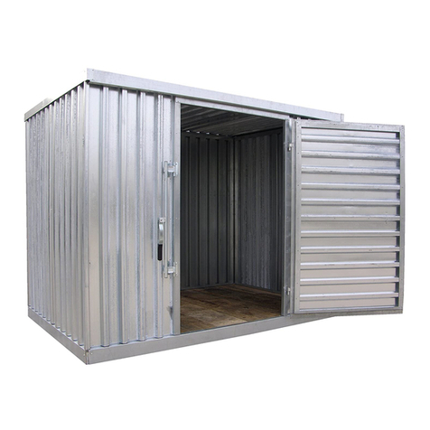
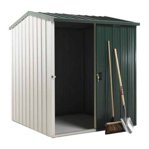
Vestil STOR-96-G-W-1RH User manual

STOR-96 and 912-G-W-1RH 0311 OWNER’S
MANUAL
STORAGE SHED MODELS:STOR-96-G-W-1RH &STOR-912-G-W-1RH
Introduction………………………. ……………….… 1
Assembly Instructions STOR-96-G-W-1RH .………..2
Assembly Instructions STOR-912-G-W-1RH……...…8
STOR-96-G-W-1RH Exploded Parts Diagram & parts
List…………………………………………….…… 17
STOR-912-G-W-1RH Exploded Parts Diagram & Parts
List………………………………………………..... 18-19
IMPORTANT NOTES,WARNINGS AND SAFETY INSTRUCTIONS
Ensure that all employees understand and follow these instructions.
Failure to read and understand this owner’s manual before using or
servicing constitutes a misuse of the product. All persons who will
install, use, or care for this product must be familiar with this material.
oEnsure that all information / safety / warning labels stay in place and are
legible.
Do not perform any modifications to the unit without the manufacturer’s
approval. Failure to receive authorization for changes to the equipment
could void the warranty.
Maintenance and repairs are to be done only by personnel qualified to
perform the required work. Consideration will not be given for warranty
repair charges without prior written authorization by the manufacturer.
STOR-96-G-W-1RH
______________________________
RECEIVING INSTRUCTIONS
It is possible that this product
could incur damage during
transit.
Inspect the unit closely when
it arrives. If you see evidence
of damage or rough handling to
either the packaging or to the
product when it is being
unloaded, immediately make a
note of it on the Bill Of Lading!
It is important that you
remove the product’s packaging
upon its arrival to ensure that
there is no concealed damage
or to enable a timely claim with
the carrier for freight damage.
Also verify that the product
and its specifications are as
ordered.
TOOLS REQUIRED
-7/16” socket or wrench
-1/2” socket or wrench
-5/16” nut driver for drill
-Level
-Eye/Hand protection advised
Note – At least two people
required to assemble this
product; three suggested
STOR-912-G-W-1RH
Page 1 of 20
STOR-96 and 912-G-W-1RH 0311
Page 2 of 20
ASSEMBLY INSTRUCTIONS
Review the bill of materials located on page 17. Unpack all materials and verify quantities before starting.
Consult the factory in the event there are any questions or problems at the time of installation, or for
information regarding optional features not covered by the owner’s manual.
---------------------------------------------------------------------------------------
SINGLE STORAGE UNIT MODEL STOR-96-G-W-1RH
Place wooden floor on clean and level surface.
Position back wall as shown above.

STOR-96 and 912-G-W-1RH 0311
Install one side wall by inserting into the lockstrip just installed on the back wall vertical end.
Page 3 of 20
Secure back wall to the wooden floor using the ¼” X 2” lag bolts into the 5 predrilled holes. Continue holding
back wall until at least two walls are connected together and lagged to the wooden floor.
Install lockstrip to both vertical ends of back wall.

STOR-96 and 912-G-W-1RH 0311
Page 4 of 20
Install 2nd side wall using foot to hold bottom of wall while inserting into lockstrip.
Secure both side walls to the wooden floor using ¼” X 2” lag bolts into the 5 predrilled holes located at the
bottom of each side wall.
Install lockstrips (2) on side walls, then insert front wall into lockstrips. Install lag bolts, ¼” X 2” lag bolts,
utilizing the 5 predrilled holes to secure front wall to the wooden floor.

STOR-96 and 912-G-W-1RH 0311
Page 5 of 20
Place roof on top of the storage unit walls and simply pull it down into the channels until it bottoms out.
Secure roof to the front and back walls with 8pc 1” long self-tapping screws. (4 pcs. per wall) These holes are
not predrilled. Space screws evenly across both sides.
Install door hinges on front wall using 4pc , 5/16” X 1” hex head bolts and 2pc threaded plates. (See following
illustrations)

STOR-96 and 912-G-W-1RH 0311
Copyright 2011 Vestil Mfg. Co. Page 6 of 20
Install hinge on front wall using threaded plate, threaded plate must be
located inside slot as shown. (see Step 11a) Install 4pc – 5/16” nut onto ends of 5/16” X 1” hex head bolts (two
bolts and nuts per hinge). Nuts not shown.
Install door to hinge using re-enforcing hinge plates(2), and 6 pc -¼”X1”carriage bolt, ¼” lock washer and
¼”nut per hinge. Align and tighten. Hinge plates must be inside building as shown.
Install locking bar. Use 6pc of ¼”X 1” carriage bolts, 6pc 5/16” washers, 6pc ¼” washers and 6pc ¼” nuts as
shown above. Rounded head of carriage bolts will be on the outside of the building.

STOR-96 and 912-G-W-1RH 0311
Page 7 of 20
Completed Unit

STOR-96 and 912-G-W-1RH 0311
Using 20pc of 2” long wood screws fasten down the spacer strips directly over the 2”X4” joints. Evenly space
wood screws along entire length of spacer strip.
Page 8 of 20
DOUBLE STORAGE UNIT MODEL STOR-912-G-W-1RH
Install joint, 2”x 4”s, to 9 foot side of each wooden floor, ¾” down from top using 6pc – 3” long wood screws,
as evenly spaced as possible per side.
Place wooden floors with 2”X4” joints together on a level surface and position pre-cut spacers as shown.

STOR-96 and 912-G-W-1RH 0311
Page 9 of 20
Install Face Joint to the center fo the two joined wooden floors using 2pc of ¼” X 2” lag bolts – one bolt per
face joint on each side for the wooden floors.
Begin assembly with wooden floors on clean level surface.
Position back wall as shown above.

STOR-96 and 912-G-W-1RH 0311
Page 10 of 20
Secure back wall to the wooden floor using ¼”X 2” lag bolts into the 5 predrilled holes. Continue holding back
wall until at least two walls are connected together and lagged to the wooden floor.
Install lockstrip to both vertical ends of back wall.
Install one side wall by inserting into the lockstrip just installed on the back wall vertical end.

STOR-96 and 912-G-W-1RH 0311
Install lockstrip on end of side wall and then install Side Fill Panel, as seen above on right hand side (see step
13 for installation)
Page 11 of20
Install 2nd sidewall using foot to hold bottom of the side wall while inserting it into lockstrip on opposite end of
the back wall.
Secure both side walls to the wooden floor using ¼” X 2” lag bolts into the 5 predrilled holes on each side.

STOR-96 and 912-G-W-1RH 0311
Copyright 2011 Vestil Mfg. Co. Page 12 of 20
Insert fill Side Fill Panel into lockstrip and add lockstrip to other Side Fill Panel. Repeat this step for other side
of storage unit.
Install next side wall panel. Repeat on other side wall. Then install 10pc ¼”X2” lag bolts to secure walls to
wooden floor. 5 predrilled holes at the bottom of each wall.
Install lockstrips (2) on each side wall, then insert front wall into lockstrips. Install 5pc of ¼”X2”lag bolts into
predrilled holes to secure front wall to the wooden floor.

STOR-96 and 912-G-W-1RH 0311
Page 13 of 20
Place roof on top of the storage unit walls and simply pull it down into the channels until it bottoms out. Repeat
with second roof piece.
Roof
panel
Roof
panel
Install the formed roof angle piece (16) between the roof panels; then install the roof seam cover plate (15) on
top of the angle piece.
NOTE: Some shed kits will combine parts 15 & 16 into a single welded cover plate. Insert the projection on the
underside of the welded cover plate into the space between the roof panels.
Secure the roof seam cover plate to roof and walls with 4 self-tapping screws. (2 screws at each end of the cover
plate)

STOR-96 and 912-G-W-1RH 0311
Page 14 of 20
Secure roof to front and back walls with 16pc
1” long self-tapping screws.(4pc per wall) These holes are not predrilled. Space screws evenly.
Install two door hinges on front wall using 4pc hex
headed bolts, 5/16”X 1” and 2pc threaded plates. (See following illustrations)
Install hinges on front wall using threaded plates. Threaded plate must be
located inside slot. Install 4pc 5/16” nuts onto ends of 5/16”x 1” hex head bolts. Two bolts and nuts per hinge.
Nuts not shown.

STOR-96 and 912-G-W-1RH 0311
Page 15 of 20
Fasten door to hinge using reinforcing hinge plates (2) and 6 pc -¼”carriage bolt, ¼” lock washer and ¼”nut per
hinge. Align and tighten. Hinge plates must be inside door as shown.
Install locking bar. Use carriage bolts (6¼in. x 1in.), 6 5/16” washers, 6pc ¼” washers and 6pc ¼” nuts as
shown above. Ensure rounded head of carriage bolt is on outside of building.

STOR-96 and 912-G-W-1RH 0311
Page 16 of 20
Fully assembled unit.

STOR-96 and 912-G-W-1RH 0311
Page 17 of 20
STOR-96-G-W-1RH EXPLODED PARTS DIAGRAM
5
7
Item No. Part No. Description Quantity
1 41-514-017 Wood base frame assembly 1
2 41-514-012 Door frame assembly 1
3 41-514-013 Side wall frame assembly 2
4 41-514-015 Door assembly 1
5 41-514-014 Rear wall frame assembly 1
6 41-514-016 Roof frame assembly 1
7 41-037-003 Lock strip 4
8 22061 Lag bolt 20
9 41-537-002 Latch lock support assembly 1
10 41-512-001 Hinge 2
11 RHSSN
Bolt ¼ in. - 20 UNC x 1in. zinc-plated carriage bolt 16
12 33006 5/16 in. zinc-plated USS flat washer 6
13 41-537-001 Lock/latch bar assembly 1
14 33004 ¼ in. type A narrow flat washer 2
15 36102 ¼ in. – 20 zinc-plated hex nut 12
16 33618 ¼ in. lock washer 10
17 41-016-002 Door bracket 2
18 41-016-001 Hinge mount door bracket 2
19 31806 Self-tapping screw 8

STOR-96 and 912-G-W-1RH 0311
Page 18 of 20
STOR-912-G-W-1RH EXPLODED PARTS DIAGRAM

STOR-96 and 912-G-W-1RH 0311
Page 19 of 20
STOR-912-G-W-1RH PARTS LIST
Item No. Part No. Description Quantity
1 41-014-030 Formed floor seam cover plate 2
2 41-514-013 Side wall frame assembly 4
3 41-514-014 Rear wall frame assembly 1
4 41-514-012 Door frame assembly 1
5 41-514-015 Door 1
6 41-537-001 Lock/latch bar assembly 1
7 ¼ in. – 20 UNC x 1in. zinc-plated carriage bolt 16
8 33006 5/16 in. Zinc-plated USS flat washer 10
9 41-014-032 Side wall frame connector 2
10 41-037-003 Lock strip 12
11 22061 ¼ in. x 2 in. zinc-plated hex lag bolt 32
12 41-512-001 Hinge 2
13 41-537-002 Latch lock support assembly 1
14 41-514-016 Roof frame assembly 2
15 41-014-026 Formed roof seam cover plate 1
16 41-014-027 Formed angle roof seam stiffener 1
17 36012 ¼ in. – 20 zinc-plated hex nut 12
18 33618 ¼ in. lock washer 6
19 33004 ¼ in. type A narrow flat washer 2
20 41-016-001 Hinge mount door bracket 2
21 41-016-002 Door bracket 2
22 41-514-018 Wooden double base frame assembly 1
23 31806 Self-tapping screw 20
Hardware
22061 21155 33618 33004 33006 36102

STOR-96 and 912-G-W-1RH 0311
Page 20 of 20
LIMITED WARRANTY
Vestil Manufacturing Corporation (“Vestil”) warrants this product to be free of defects in material and workmanship during
the warranty period. Our warranty obligation is to provide a replacement for a defective original part if the part is covered
by the warranty, after we receive a proper request from the warrantee (you) for warranty service.
Who may request service?
Only a warrantee may request service. You are a warrantee if you purchased the product from Vestil or from an
authorized distributor AND Vestil has been fully paid.
What is an “original part”?
An original part is a part used to make the product as shipped to the warrantee.
What is a “proper request”?
A request for warranty service is proper if Vestil receives: 1) a photocopy of the Customer Invoice that displays the
shipping date; AND 2) a written request for warranty service including your name and phone number. Send requests by
any of the following methods:
Mail Fax Email
2999 North Wayne Street, PO Box 507 Phone
Angola, IN 46703 (260) 665-7586
In the written request, list the parts believed to be defective and include the address where replacements should be
delivered.
What is covered under the warranty?
After Vestil receives your request for warranty service, an authorized representative will contact you to determine whether
your claim is covered by the warranty. Before providing warranty service, Vestil may require you to send the entire
product, or just the defective part or parts, to its facility in Angola, IN. The warranty covers defects in the following original
dynamic components: motors, hydraulic pumps, electronic controllers, switches and cylinders. It also covers defects in
original parts that wear under normal usage conditions (“wearing parts”): bearings, hoses, wheels, seals, brushes,
batteries, and the battery charger.
How long is the warranty period?
The warranty period is 90 days, and the period begins on the date when Vestil ships the product to the warrantee. If the
product was purchased from an authorized distributor, the period began when the distributor shipped the product. Vestil
may extend the warranty period for products shipped from authorized distributors by up to 30 days to account for shipping
time.
If a defective part is covered by the warranty, what will Vestil do to correct the problem?
Vestil will provide an appropriate replacement for any covered part. An authorized representative of Vestil will contact you
to discuss your claim.
What is not covered by the warranty?
1.Labor;
2.Freight;
3.Occurrence of any of the following, which automatically voids the warranty:
Product misuse;
Negligent operation or repair;
Corrosion or use in corrosive conditions;
Inadequate or improper maintenance;
Damage sustained during shipping;
Accidents involving the product;
Unauthorized modifications: DO NOT modify the product IN ANY WAY without first receiving written
authorization from Vestil. Modification(s) might make the product unsafe to use or might cause excessive
and/or abnormal wear.
Do any other warranties apply to the product?
Vestil Manufacturing Corp. makes no other express warranties. All implied warranties are disclaimed to the extent allowed
by law. Any implied warranty not disclaimed is limited in scope to the terms of this Limited Warranty.
Other manuals for STOR-96-G-W-1RH
1
This manual suits for next models
1
Other Vestil Outdoor Storage manuals
Popular Outdoor Storage manuals by other brands

Arrow Storage Products
Arrow Storage Products CLG65CC Series Owner's manual & assembly guide

Arrow Storage Products
Arrow Storage Products CLG67CC Owner's manual & assembly guide

megiw4garden
megiw4garden Zawilec manual

Bartscher
Bartscher KOMBI52L instruction manual

Moebelix
Moebelix BS-T2D owner's manual

Arrow
Arrow GD106-A Owner's manual & assembly instructions