100505.01 7
NEDERLANDS
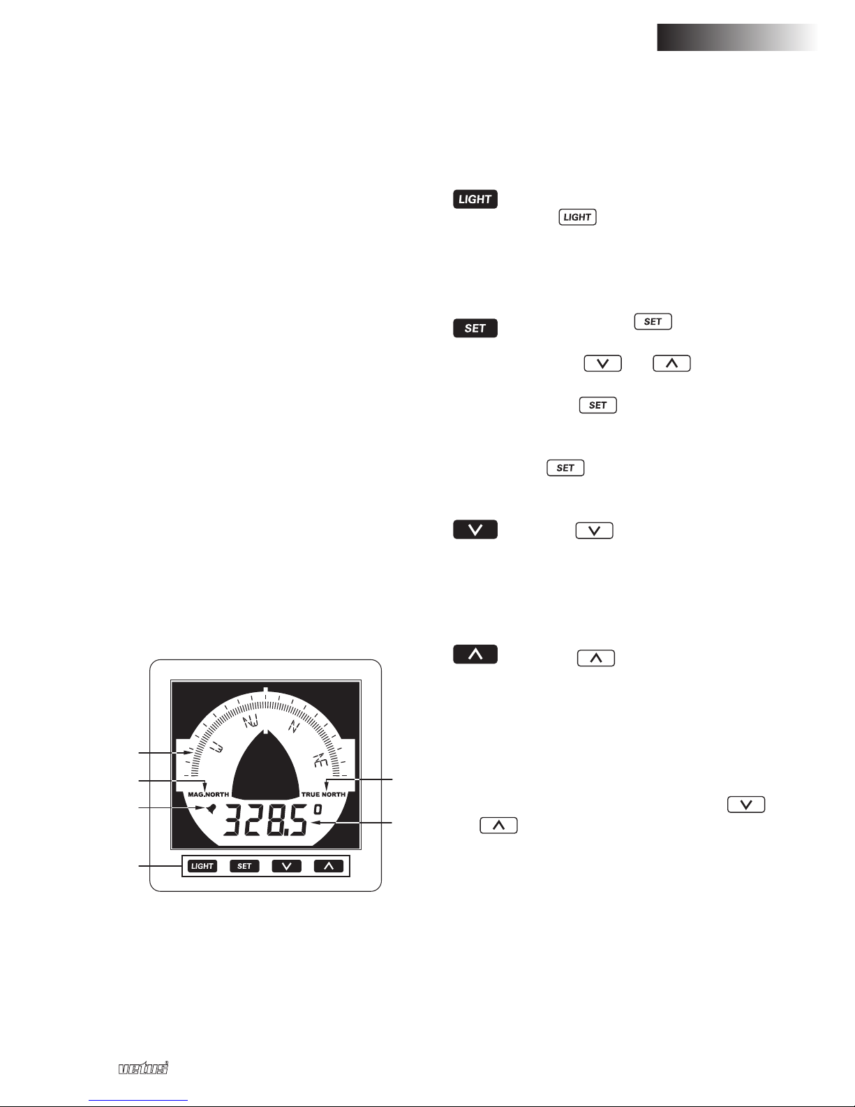
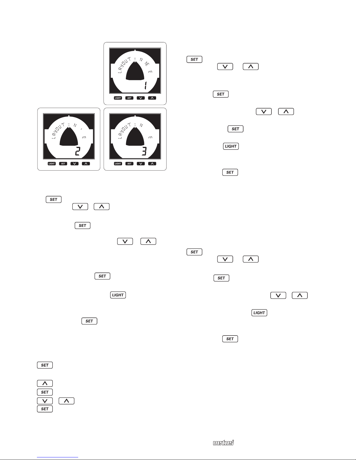
Electronisch kompas EC
4.1.6 Kalibreren (ST6)
Ook de magnetische invloeden van het
schip zelf kunnen kompasafwijkingen
veroorzaken.
U kunt deze magnetische afwijkingen cor-
rigeren door het kompas te kalibreren.
• Druk in het hoofdscherm op de knop
om de menu’s te openen.
• Druk op / om het menu
kalibreren (Calibration) te selecteren
(ST5).
• Druk op om het menu kalibreren
te openen.
• Kies met de knoppen /
automatisch (Auto) of handmatig
(Manual).
4.1.6.1 Automatisch kalibreren
Dit elektronisch kompas kan zichzelf
automatisch kalibreren. Standaard staat
‘Automatisch kalibreren’ op aan ‘ON’.
De kompassensor zal zichzelf kali-
breren als u met constante snelheid
twee volledige cirkels vaart binnen 1 tot
maximaal 4 minuten per cirkel.
U kunt deze functie ook uitschakelen en
in plaats daarvan handmatig kalibreren.
4.1.6.2 Handmatig kalibreren
Kalibreer de kompassensor alleen bij kalm
weer en in een scheepvaartvrij gebied.
Laat uw schip met constante snelheid een
ruime cirkel varen. Selecteer vervolgens
‘kalibreren’ in het menu en druk de knop-
pen en samen twee seconden
lang in. In het scherm verschijnt nu de
koers en de tekst ‘bezig (In process)’.
Zorg dat uw schip de cirkel (de volledige
360°) tussen de 1 en maximaal 4 minuten
voltooit. Als het kalibreren is gelukt komt
er ‘klaar (Done)’ in het scherm te staan en
klinkt er een kort piepje. U mag de cirkels
zowel linksom als rechtsom varen.
Indien de cirkel niet binnen de gestelde
tijd werd gevaren, blijven de bestaande
kalibratiegegevens bewaard en kunt u in
het display aflezen of het rondje te snel of
te langzaam is gevaren.
Voorbeeld:
• Laat uw schip een ruime cirkel varen.
• Open het menu kalibreren en selecteer-
handmatig kalibreren, druk op
• Druk 2 seconden lang tegelijk op
en -> ‘bezig (In process)’
• Blijf de cirkel varen en wacht tot het
kompas piept.
In het scherm staat nu of het kalibreren
is gelukt of niet.
4.1.7 Uitlijning (ST7)
Corrigeer uitlijnfouten door enkele bek-
ende koersen uit te zetten op een kaart
en de magnetische koersen daarvan te
vergelijken met de magnetische koers die
het kompas aangeeft. U kunt eventuele
verschillen compenseren met de uitlijn-
waarde.
• Druk in het hoofdscherm op de knop
om de menu’s te openen.
• Druk op / om het menu
uitlijnen (Align) te selecteren (ST7).
• Druk op om het menu uitlijnen te
openen.
• Corrigeer de afwijking met de knop-
pen / U kunt deze waarde
wijzigen in stappen van 0,1° tot max.
+/- 99°.
• Druk op om naar het hoofd
menu te gaan of:
• Druk langer dan twee seconden op
de knop om terug te gaan
naar het hoofdscherm.