VEVOR CUT-50 User manual

PLASMA CUTTING MACHINE


This is the original instruction, please read all manual instructions carefully before operating.
be subject to the product you received. Please forgive us that we won't inform you again if
there is any technology or software updates on our product.
PLASMA CUTTING
MACHINE
01

SAFETY
Plasma cutting is dangerous, and may cause damage to you and others, so take good protection
when cutting. For details, please refer to the manufacturer's safety guidelines for accident prevention.
02

INTRODUCTION
FUNCTIONAL DIAGRAM
CUT-50/CUT50P Air plasma cutting technology.Plasma cutters work by passing an electric arc through air/gas
which is passing through the narrow opening. The gas can be air, nitrogen, argon, oxygen, and etc. The electric
arc elevates the temperature of the gas to the point that make it enters a 4th state of matter. We all are familiar
with the rst three state: solid, liquid, and gas. Scientists call the fouh state plasma. As the metal being cut is
pa of the circuit, the electrical conductivity of the plasma causes the arc to be transferred to the work.
The gas passes through the restricted opening (nozzle) which make it be squeezed at a high speed, like air
passing through a venturi in a carburettor. This high speed gas cuts through the molten metal.
Plasma cutting was invented as the result of ting to develop a better welding process. Many improvements
have made the technology what it is today. Plasma cutters provide the best combination of accuracy and speed,
and the ability of producing a variety of at metal shapes. They can cut much ner and faster than oxyacetylene
torches.
1
2
3
4
6
7
5
03

1. Current display meter
The digital ammeter is used to display the actual output current of the power source.
2. Power indicator light
Turn on the power, and this light will be on.
3. Fault light
When the welding load is overloaded and the output current of the machine is too large, this light will be on.
This situation is normal and the machine can recover itself. When there is damage inside the machine, this light
will be on. In this case, the machine is abnormal and requires maintenance.
4. Adjust the value knob
Clockwise rotate the knob to enlarge the current, and anti-clockwise rotate the knob to reduce the current.
5. Cutting gun cable and gas connection seat
Remove the black cap and connect the cutting gun.
6. Cutting gun control socket
That is two-core aviation socket. The cutting gun triggers switch to control connection.
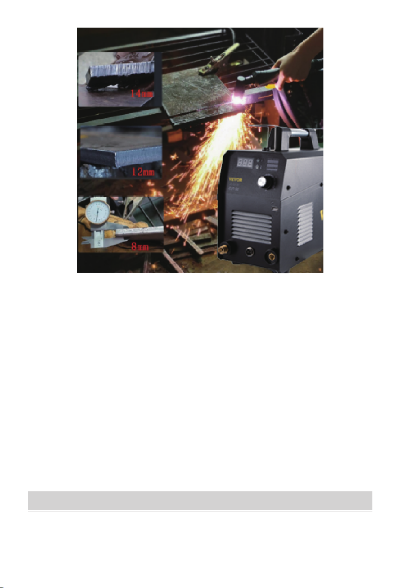
CUT50/CUT50P
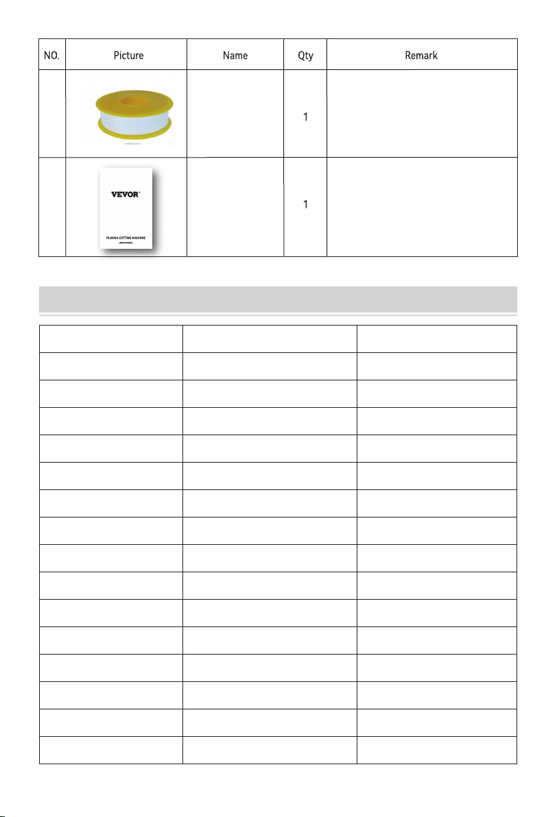
Please check the exterior of the whole
machine to ensure there is no scratch
or damage, and the machine can be
CUT50:L=4m SG55 Cutting gun.
CUT50P:L=5m AG-60 Cutting gun.
L=2M , 10mm² Copper Clad Aluminum
Wire; Rubber Jacket + 300A
Ground Clamp
Ground Clamp
SG55/AG-60
Cutting gun
7. Negative Welding Terminal
Welding current ows from the power source to heavy duty bayonet type terminals. It is essential that the male
plug is securely inseed and turned to achieve a sound electrical connection.
INTRODUCTION TO THE PRODUCT AND CONFIGURATION LIST
04

Adjust cutting air pressure.
Pressure
Reducing
Valve
4
air leakage
Electrode
to be replaced frequently. Please
keep stock.
12
11 M4 screws are used to x the cable
suppo to the machine.
The cable holder needs to be xed to
the machine. It can store the power
cable, ground wire or welding torch.
be replaced frequently. Please keep
stock.
Copper Nozzle
Pressure
Reducing
Valve Outlet
Connector
Quick gas connector ensures
direct plug-in.
Adapter
Screw
Cable Holder
4
2
•
compatible with dual voltage devices
220V to 110V or vice versa)
• Check your device’s voltage to ensure it
05

TECHNICAL SPECIFICATIONS
TYPE
Input power voltage (V)
Rated input current (A)
Rated power capacity (KVA)
Current adjustment range (A)
USB
Voltage adjustment range (V)
No-load voltage (V)
Rated duty cycle
Power factor
Protection class
Insulation class
Size (mm)
Weight (Kg)
CUT50
50/60Hz
110V:50A 220V:37A
110V: 6.6KVA 220V: 5.5KVA
20-50A
5V/1A
88-100V
300±30V
0.7
IP21S
F
360*150*300
5.76
CUT50P
50/60Hz
110V:50A 220V:37A
110V: 6.6KVA 220V: 5.5KVA
20-50A
\
88-100V
300±30V
0.7
IP21S
F
360*150*300
6.26
06
Manual
14
13
This is a English manual, if you
need other language like French,
German, Italian, Spanish, and Russian
please contact us to get electronic
version documents.
Used to seal the joint of threaded
air pipe to prevent air leakage.

CUT50 Plasma cutting machines will be subjected to various strict tests before leaving
the facto. This is for ensuring that each welding machine that reaches the user is of high
quality. Because our machines have to go through tens of thousands of kilometers of
long-distance transpoation from the facto to your hands. In this process, it’s
inevitable that some uncontrollable factors will lead to the loosening or even damage of
some components inside machine. We recommend that you check its external as soon as
you get the welder, and turn on the power to check if you have received a qualied product.
Tips:
1. Wear a welding helmet with appropriate lters to protect your face and eyes when
welding or watching.
2. Wear approved safety glasses. Side shields are recommended.
3. Use protective screens or barriers to protect others from ash and bright lights and
warn others not to watch the arc.
4. Wear protective clothing made from durable, ame-resistant material (wool and
leather) and foot protection.
5. If there is too much noise, use approved earplugs or earmus.
MACHINE OPERATION GUIDANCE
SIMPLE TEST FOR POWERING ON THE MACHINE
1. Please make sure your power supply voltage is 110V±10%/ 220V±10%.
2. It is recommended to choose 50A circuit breaker protection.
3. Please choose the power plug that suits your local electrical law requirements for
this machine.
4. Extension cord: Choose #12 AWG or larger one; choose 25’ (8m) or shoer one.
2 PRECAUTIONS FOR POWER-ON INSPECTION:
07

OPERATION
Note:
1. Normal phenomena: The digital display shows irregular changes at the beginning,
and then returns to the digital display after 3 seconds.
2. In order to reduce the working temperature of the machine, the inside fan would
continue to rotate for a few seconds after the power is turned o.
3. Normal phenomena: Machine protection may occur during high strength continuous
welding. After continuous heat dissipation, the machine would return to normal state.
Attached table:
Self-examination of abnormal conditions when turning on the machine:
1. The machine's power switch is not turned on.
2. The power input voltage is wrong.
3. The power plug is loose.
4. The internal circuit is loose (due to long-distance transpoation, bumps),
and you need to open the cover and check the internal connection.
CUT mode
If you want to cut any metal objects, please use this plasma cutting machine.
Turn on the power switch of the machine, and the fan on the back of the machine rotates,
and the digital display on the panel indicates that the power is normal.
08

2. Connector cover.
3. Connect compressed air.
1. Connect welding holder and ground clamp.
09

4. How to use air regulator.
5. Adjust the current, and only the current can be adjusted.
1. Turn clockwise to increase the pressure 2. Pull up 3. Pull down
4. Air regulator 5.Air/Water lter 6. Release Water
7. Rotate counterclockwise to lower the pressure
10

Cutting operation
2. Hand torch cutting technique.
Make sure the spark ows
out of the bottom of the
workpiece when cutting.
If sparks erupt from the top
of the workpiece, you are
moving the torch too fast or
you are not setting enough
amperes.
Hold the torch veically and
watch the arc as it cuts along
the line.
As a rule of thumb, the thicker the material, the greater the current required. Set the machine to full output and
va your moving speed when you are cutting thick material. Turn down the amperage and change it to a
lower-amperage tip to maintain a narrow ke when you are cutting thin material. The ke is the width of the
cut material that is removed during cutting.
Amperage
1. Sta Cutting.
Hold the torch veically at
the edge of the workpiece.
Pull the trigger to sta the arc.
The cutting arc will sta working
when the torch tip is close enough
to the workpiece. Begin cutting
the edges until the arc passes
through the metal plate.
Then continue the cutting.
3. Piercing.
Hold the torch at an ceain angle to
the workpiece, and pull the trigger
to sta the arc, and slowly rotate it
to the position perpendicular to the
workpiece.
By the time the spark is shot
from the bottom of the
workpiece, the electric arc has
already penetrated the material.
When the pierce is complete,
continue cutting.
11

Current and speed are key to producing good quality cuts. The faster you move (especially aluminium) the
workpieces, the cleaner cut you will get. To determine if you're moving too fast or too slow, you can look at
the arc that comes from the bottom of the cut. The arc should move away from the material at an angle away
from the direction of motion. If the arc going straight down, that means you're moving too slow, and you'll
get the buildup of dross or slag. If you are moving too fast, the arc will sta spraying back onto the suace
of the material without cutting through it. Because the arc trails at an angle, slow your cutting speed at the
end of a cut and it will cut through the last bit of metal.
Speed
It is easier to pull the torch towards you than push it. The plasma stream swirls as it exits the tip, biting one side
and nishing o on the other side, and it will leave a bevelled edge and a straight edge. Bevel cutting is more
obvious on thicker materials. If you want the straight edge to be on the nished product, you need to consider
this point before cutting.
Direction
The distance and relative position between the plasma torch tip and the workpiece woill aect the cutting quality
and the cutting bevel. The easiest way to reduce the slope is to cut at the right speed and height and current.
Torch tip height & position
This is correct height and square between the torch
and the material. Minimum bevel& equal bevel ensure
longest consumable life.
This is unequal bevel, and one
side may be excessively beveled.
Torch is too far from the workpiece.
The plasma stream may not cut through
the material with excessive bevel.
Torch is too close to workpiece.
The tip of the torch may contact the
work piece and will be sho out or
damaged when there is reverse bevel.
12

The tip orices focus the plasma stream to the work piece. It is impoant to use the correct size of tip for the
appropriate amperage. For example a tip with a 3/64" orice is good for 0-40 amps whereas a 1/16" orice is
good for 40-80 amps.
The low-amp tip has a smaller orice which maintains a narrow plasma stream at lower settings and it is used
for thin-gauge material. Using a 25 amp tip at an 60 amp setting will blow out and disto the tip orice. And it
may require a replacement.
Conversely, using an 80-amp tip on the lower settings will not allow you to focus on the plasma stream and
create a wide ke. The condition of the tip orice is critical to the quality of the cut result. A worn or damaged
tip orice will produce a distoed plasma stream, resulting in a poor cutting quality.
Tip size and condition
A xed gap is established between the electrode and the inside of the cutting tip. Electrons arc comes across
the gap to ionize and super heat the air, creating the plasma stream. The electrode contains an inse in the end
which is made of a highly conductive material called hafnium. This inse erodes with use and develops a pit in
the end of the electrode. When the pit becomes too much, the cuts will be poor quality. And it is necessa to
replace a new electrode.
Electrode condition
• It is easier to pull the torch through the cut than to push it.
• To reduce the amperage when you are cutting thin material until you get the best quality cut.
• Use the correct size of tip orice for the appropriate amperage.
• Use a straight edge or cutting buggy as a guide for straight cutting. Use a template or circle cutting
attachment for a template or circle cutting.
• Check whether the vulnerable pas at the front of the plasma cutting torch are intact.
Technique Tips
Air pressure, ow rate and air quality are critical to the quality of plasma cutting and the life span of consumable.
The required air pressure and volume can va from model to model and the manufacturer will provide the specs.
The CUT35 air pressure is preset at 4.5 psi and requires a ow rate of 6.0 CF/M. The volume capacity of your
compressor is impoant, if you have a small compressor with exactly the same l/min rating as the plasma, then
the compressor will run continuously. When you are doing plasma cutting, a compressor with a l/min rating
slightly higher than the plasma is more appropriate. If you are doing a lot of cutting and you are cutting thick
plate (same air consumption but slower cut speeds = longer cut time), choose a compressor at 1.5 to 2 times is
enough.
Air pressure and volume
Good air quality is essential to the quality of plasma cutting and the life span of consumable. Compressors take
in air at atmospheric pressure and increase the pressure to store it in a tank. The humidity in the air condenses
in the tank and creates moisture in the airline, especially in humid conditions. Moisture that forms in air lines
has a tendency to condense into larger drops when the air pressure decreases and enters the plasma torch.
When these droplets enter into the (as much as 19832°f) torch with high temperature, they immediately break
down into oxygen and hydrogen, which alters the normal chemical content of air in the torch. These elements
will then dramatically change the plasma arc which causes the quick abrasion of torch consumable pas. And it
also alters the shape of the nozzle orice, dramatically aecting cut quality in terms of edge squareness, dross
formation, and edge smoothness. Minimizing the moisture in the air supply is absolutely critical to the quality of
plasma cuts and the longevity of consumable pas. Be sure to drain the receiver (tank) on the air compressor at
least daily. Most air plasma systems comes from reputable manufacturers have a paiculate lter or a coalescing
lter with an auto drain that will remove some moisture from the air supply. For home workshop and light
industrial users the on board air lter is adequate. However most situations will require additional ltration to
prevent moisture from aecting the quality of the plasma cutter. And in most cases it is recommended to install
a sub micronic paiculate lter which is designed to trap water through absorption. This style of lter has a
replaceable lter caridge that absorbs water and it must be changed after it is near the saturation. And it
should be installed as close as possible to the air intake of the plasma cutter.
Air quality
13

CAUTION
1. The installation environment of the welding equipment must be free of grinding dust, corrosive chemicals,
ammable gases or materials etc, and the humidity shall not exceed 80%.
2. When using the machine outdoors, please avoid direct sunlight, rain, snow, etc to our machine. The operating
ambient temperature shall be maintained at -14°F to +104°F.
3. Keep this equipment away from the wall.
4. Ensure that the working environment is well ventilated.
Working Environment
A dusty, damp or corrosive environment can cause damage to the welder. In order to prevent any possible
failure or fault of this welding equipment, clean the dust regularly with clean and d compressed air with
required pressure.
Please note that: Lack of maintenance may result in warranty cancellation. The guarantee of this welding
equipment will be void if the machine has been modied, or you attempt to take apa the machine or open the
facto-made sealing of the machine without the consent of an authorized representative of the manufacturer.
Maintenance
Caution: Only qualied technicians are authorized to undeake the repair of this plasma cutter equipment.
For your safety and to avoid electrical shock, please obsee all safety notes, precautions, and details in this
manual.
Trouble shooting
Basic plasma cutters use electricity to superheat air and let it enters into plasma state(the 4th state of
matter), which is then blown through the metal. Plasma cutters require a compressed air supply and AC
power during operation.
How dose a plasma cutter work?
1. Ventilation
This equipment is small-sized and compact in structure, and it has excellent peormance in amperage output.
The fan is used to dissipate heat during operation.
Impoant: Maintain good ventilation of equipment louvers.
The minimum distance between this equipment and any other objects should be 1ft. Good ventilation is
impoant for the normal peormance and the seice life of this equipment.
Safety Tips
2. Thermal Overload protection
If the machine is overused or it is used in high temperature environments or poorly ventilated areas, or the fan
is damaged, the thermal overload switch will be activated and the machine will stop running.
In this case, keep the power on and the built-in fan would working to lower the temperature inside the device.
And the machine will be ready for use again when the internal temperature reaches to a safe level.
3. Over-Voltage Supply
See table "Main Parameters" for the range of supply voltage.
This device has automatic voltage compensation function to keep the voltage range within a given range.
If the voltage of input power supply amperage exceeds the stipulated value, it is possible to cause damage
to the components of this equipment. Please ensure your prima power supply is correct.
4. Do not touch the output terminals while the machine is in operation.
An electric shock may occur.
SAFETY PRECAUTIONS
14

1. Ring 2. Nozzle 3. Plasma Stream
4. Shield Cup 5. Electrode 6. Steel
1. When the trigger is squeezed, DC current ows through the torch into the nozzle.
2. Next, the compressed air ows through the torch head and the air diuser which spirals the air ow around
the electrode with last ows through the hole of the cutting nozzle.
3. A xed gap is established between the electrode and the nozzle. (The power supply increases voltage in order
to maintain a constant current.) The electrons form an arc in the void, and then ionize and heat the air to form
a plasma stream.
4. Finally, the regulating DC current is switched so it does not ow to the nozzle but ow from the electrode to
the workpiece. Current and ailow would continue run until the cutting is stopped.
Operation
Notes:
1. The nozzle and electrode require periodic replacement. The electrode has an inse of tough high conductive
material such as hafnium and cerium. The inse will corrode with use, as will the nozzle hole.
2. The quality of air is critical to the life of electrodes and nozzles; in sho, clean and d air provides longer
component life. We recommend using a plasma air lter.
3. It is recommended to cut from the edge of the workpiece.
15

Problems
1. The power indicator does not
light when power up, and the
fan does not work, and the
torch also does not work while
press torch trigger.
1. No power supply enters the
machine through cable.
2. The power cable, switch or
other wire is loose.
3. Power cable inside of machine
are not connected well.
4. There is a problem with the
power board.
1. Check the power input.
2. Check the power cable,
power switch, power plug
and all wires inside of machine.
And Check whether the cable
between the power switch and
the motherboard is loose.
3. Change the board.
Analysis Solution
Viually any metal can be plasma cut including steel, stainless steel, aluminium, brass, copper, etc. Depending
on the power of the plasma cutter, you can cut any thickness from 30" to 9/16 ".
What kinds of materials can the plasma cut?
Plasma cutting can be peormed on any type of conductive metal, such as mild steel, aluminium and stainless.
Compared with alloys, the operators will experience faster, thicker cuts with mild steel. Oxy-fuel cuts by burning,
or oxidizing the metal. It is therefore limited to steel and other ferrous metals which suppo the oxidizing process.
Metals like aluminium and stainless steel form an oxide that inhibits fuher oxidization, and this making
conventional oxy-fuel cutting impossible. Plasma cutting does not rely on oxidation and thus it can cut
aluminium, stainless and any other conductive material. While dierent gasses can be used for plasma cutting,
now most people use compressed air for the plasma gas. In most shops, compressed air is readily available,
and plasma does not require fuel gas or compressed oxygen for operation. Plasma cutting is typically easier for
the novice master, and plasma cutting is much faster than oxy-fuel cutting for thinner materials. For heavier
steel sections (1 "or larger), oxygen fuels are still preferred because oxygen fuels are generally faster. For heavy
plate applications, high power plasma cutting machines are required for plasma cutting applications.
How does plasma cutting compare to oxy-fuel (gas) cutting?
The plasma cutting machines are usually more expensive than oxy/acetylene. In addition, oxy/acetylene does
not require electricity or compressed air, making it a more convenient method for some users. Generally,
oxyfuel cuts thicker steel plates (>63/64 inch) faster than plasma cutting.
What are the limitations to plasma cutting? When is oxy-fuel preferred?
The plasma cutting process involves creating electrical channels for superheated ionized gas. That is, the plasma
stas from the plasma cutter itself, and forms a complete electric circuit through the workpiece and the
grounding clamp, and then returns to the plasma cutter. This is done by compressing gases (oxygen, air, ine
gases and other gases depending on the material being cut) through a concentrated nozzle and then blowing
them at high speed towards the workpiece. The electrical arc is formed in the gas, or integrated into the gas
nozzle. The electrical arc ionizes some of the gas and produces a conductive channel of the plasma. As the
electricity spreads the plasma from the cutter torch, it also provides enough heat to melt the workpiece.
At the same time, many high-speed plasma and compressed gases blow away the hot molten metal,
thus it can separate and cut the workpiece.
Plasma Introduction
NOTE: This machine is designed to use only compressed air as gas.
TROUBLESHOOTING
16

Problems
2. The power indicator dose not
light up after switch on, and the
fan only works some seconds,
and the machine stops working
once the torch touch the metal
1. There is a problem with the
times causes the machine to
overheat and fail to work.
1. Check the power components
or change the main board.
2. Let the machine rest for a
3. The power indicator lights after
switch on machine, and the fan
also works. But the machine
stop working when you press
the torch trigger.
1. Check whether the welding
torch switch is loose.
2. The torch switch is loose or
any wires are loose.
3. The switch wires inside of the
torch is loose.
1. Check if any torch wires
are loose.
2. Check if any wires of the torch
is loose.
3. Check if any wires inside of
machine is loose.
4. The power indicator lights and
the fan works.HF sparks while
press torch trigger but no air
blow out of torch head(or the
air keep blowing out). The
electric valve does not work.
1. Check whether the welding
torch switch is loose.
2. The torch switch is loose or
any wires are loose.
3. The switch wires inside of the
torch is loose.
1. Check if any torch wires
are loose.
2. Check if any wires of the torch
is loose.
3. Check if any wires inside of
machine is loose.
5. Power indicator lights up,
but O.C indicator does not light.
The fan works and the gas blow
out of torch after pressing torch
trigger ( gas valve works).
There is no HF.There is arc
between metal and electrode.
1. Arc striking coil is loose.
2. HF capacitor 102-10KV is
broken.
1. Check if any wires are loose.
2. Replace the HF capacitor.
6. The power indicator lights up,
and the fan works.The gas blow
out of torch while pressing
trigger, and O.C lights while
pressing torch trigger.
1. There is a problem with
the diode.
2. There is a problem with
the IGBT.
it if there is any damage.
2. Check IGBT, resistor, and diode
to see if there is any damage,
replacing it if any one is
damaged.
7. The power indicator lights,
and the fan works. Air can blow
out of torch head after pressing
torch trigger. The O.C indicator
does not light, but it is lighting
up while cutting.
1. There is a problem with the
circuit . Check IC3140 and
other components to see if
there is any problem.
if any wires are loose.
2. Replace the board.
8. The cutting current can not
be adjusted.
1. The wires are loose or the
potentiometer is damaged.
2. There is a problem with the
setting circuit.
1. Check the potentiometer if the
voltage. Replace it if there is
any damage.
2. Check if any wires are loose
from front board to main board.
3. There is a problem with the
boards.
Analysis Solution
17

9. The machine shuts down
1. The power cable or circuit
2. There is a problem with
the silicon.
1. Fix or replace it.
2. Check and replace it.
3. Replace the silicon bridge.
10. After pressing the torch
trigger, there is a HF sound
and sparks, but the arc
1. The welding torch is broken
or loose; Or there is poor
2. The positive or negative
terminal of the connector
is loose.
1. Improper clearance between
tip and metal. The tip and
electrode is damaged or
oxidized.
2. The HF is weak because of
the board leakage.
3. The GAS/AIR connector is
damaged, and there is power
leakage between the
connector and the front panel.
1. Adjust the tip to the metal
at the correct gap.
12. The HF keeps sparking after
pressing the torch switch.
1. The HF signal is transmitted
to the torch switch board
and disturbed it.
1. Check the GAS/AIR torch
and torch switch connector to
see if there is any HF sparks
between them and the front
metal.
Problems Analysis Solution
18
This manual suits for next models
1
Table of contents
Other VEVOR Welding System manuals